1
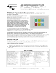
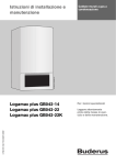
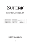
Jed Micro Pty Ltd
5/173 Boronia Rd, Boronia, Victoria, 3155, Australia
Phone: +61 3 9762 3588
www.jedmicro.com.au email: [email protected]
T430 Simple Projector Controller user’s manual version V107 (part A)
(Ed Schoell rev: Sept 21st 2015)
The T430 is a wired (RS232) remote controller for video projectors
and flat panels, allowing simple On-Off control of the system, and
optionally a simple toggle between two channels or sources.
Ease of setup and installation has been an important design
criterion, and this has been achieved by providing a data-base of
pre-coded projector code families in all units, so all have identical
software (which is field up-dateable). At install time, or whenever
options (or projectors) are changed in a room, the changes are
made by selecting device families with the “Program select” hex
switches on the back of the unit.
Two keyboard styles are provided, one with just an OFF and an
ON key, and one with an OFF and an ON/Source key. This later
allows toggling between two sources, from a mix of Computer and
Video.
A DIP switch allows installers to quickly select several extra
options, including which keyboard is installed and sources.
Connections: Power, one serial port, PIR (Passive Infra Red)
sensor, optional IR projector drive or an optional CAT5 cable to
the A/V world. An optional output can also drive a USB switch.
Several variables can be setup at install time, allowing for variable
warm-up and cool-down times, timeout time for automatic PIRcontrolled turnoff, and allocation of a wide range of computer or video channels to the source choices.
Except for a major code upgrade for totally new devices, a laptop is never needed at install/setup time. There is ¼
Mbyte of memory in the unit for data-base storage. A boot loader is included in the CPU, located in upper memory, so
no special programming dongles are needed; it just needs a PC with a serial port (or a USB to serial adaptor.)
Note: The T430 actually uses a T440 circuit board with custom parts loading and custom software … this is why
the T430 drawings and PCB label shows T440, and why the T430 and T440 share part B user’s manuals.
Operation of the T430
Red and green LEDs are next to the OFF and ON/Source keys respectively. These are steady or flashed to signal to the
user the current state of the system. Pressing keys moves the operation through these various states.
Table of Contents
Operation of the T430
1
Rear view and T430 connections 2/3
Setting up the T430 switches
3
Selection switch for options
3/4
Selection of program/projector
4
Setting of T430 constants
4/6
USB sw./Power ON relay interface 6
PIR in for automatic turnoff
6
OPT3: PIR in for timer Off
7
Serial access to T440 setup info
7
Factory reset of constants
8
Readout of version number
8
OPT7: Detection of proj. shutdown 8
Configuring the T430
8/9
T430 User’s manual V107A, © Jed Micro Pty Ltd
Reprogramming of the CPU
10/11
Wiring the T430
12
Trouble-shooting the T430 setup12/13
Keyboard options
14
Wiring diagram
15
Page 1
Off state (Blink codes)
In the OFF state, the red LED by this key glows continuously. A built-in test function is provided, which can be
actuated by pressing the OFF key in this OFF state. This sends a test signal to the connected projector and blink codes
show:
•
If the red LED flashes ONCE, it indicates that communications was established correctly, and the reply was as
expected;
•
If the red LED flashes THREE times, it indicates a communications error, i.e. a disconnected or powered-off
projector, a wiring fault, or a wrongly-set “Program select” switch on the back;
•
If there is NO flash, it indicates that this particular projector normally has no response in the standby state, or an
example projector has not had timing measurements done yet, so polls aren’t tried;
•
After none, one or three flashes, the red LED glows continuously.
Turn-on
Pressing the ON key starts the T430 warm-up cycle. This will send the “start-up” code to the projector.
The green LED by the ON button will flash once per second, for the pre-set warm-up time.
Warm-up
The warm-up time is preset and varies from projector family to family. The time can be altered at setup time to suit
individual models in a manufacturer’s range over a range of 1 to 159 seconds. See the following section: “Constant
setting” for instructions on how to do this.
Run mode
At the end of the warmup time, the green LED will then flash for a short “lockout” period, and the chosen “channel
select” command is sent to the device. It will start on the last (previously) used source/channel.
If a On/Source keyboard option is used, pressing the On/Source key again will toggle to an alternate source. The DIP
switch selects the channel/sources which are toggled between. On source change the green LED flashes during a
lockout time while the projector/panel changes channels. (If an “On” only keyboard is used, pressing the ON key again
with send an “Auto-Pixel-Align” command (for a Computer channel) if it is available and needed by that projector.
(Setting OPT2 switch ON will automatically send an “Auto-Pixel-Align” 30 seconds after any channel change to a
“Computer” channel, in either keyboard configuration. (This time can be adjusted by altering Constant:7.)
Closedown
When the OFF key is pressed, the following actions happen:
• The projector is sent the “Powerdown” message;
• The OFF red LED starts flashing once per second.
At the end of the Cooldown period, the system returns to the OFF state above. (The actual Cooldown period can be
programmed by a constant setup (see later).
Rear-view of the T430
Looking at the back of the T430 shows the connections and the
setup switches. These can vary depending on the configuration
ordered: If (green) Phoenix connectors used, (as in the photo to
the right), they are as follows:
T430 Connections: Phoenix option
•
At the bottom-right is a Phoenix connector for projector
RS232 serial connection: same pinout as the T440/T460,
with Ground, Tx (data out), Rx (projector reply) and CTS
(optional, infrequently used);
•
At the far left is the power input, in the range of 9 to 25
volts. Current is under 50mA but depends on voltage;
T430 User’s manual V107A, © Jed Micro Pty Ltd
Page 2
•
Optional: 2-pin IR transmitter output (IR option only),
just to the right of the power connector;
•
At the top left is two-terminal connection J3, the PIR
sensor input.
•
Optional: Relay 3, a “USB switcher drive” or a
“Power On relay drive.”
T430 connection: CAT5 option
Just left of centre in the photo to the right is a CAT5 socket.
This is a quick wiring option for the communications, power,
and PIR to user wiring or the T447 “cable-top” box, which provides terminations to the projector (DB9), power in
socket, and PIR screw terminals. (It is NOT an Ethernet connection, and wire colours are later in this manual section.)
T430 Switches:
•
Two hex switches provide “Program Select” to select
an entry in the data-base of projector/flat panels. Use
a screwdriver to select codes from 00 to FF;
•
One 8-position “Option” switch, allows installers to
select options, eg alternate video or computer sources,
auto-send of pixel align and keyboard type;
•
One “Reset” switch, used to enter “program re-load”
or manually set “constants” such as time delays, etc.
This is a small push-button switch.
Setting up the T430 switches
Selection of Options
An 8-switch options selection switch (SW4) is used to
select install-time options.
NOTE: The OFF (default) position is with all sliders DOWN (by the switch numbers and green connectors).
Moving a switch to the ON position selects the option, as defined in this table:
Switch
On Function
Switch
On Function
OPT1
On: Swap Video 1 (usually Composite) and
Video 2 (usually HDMI) sources, i.e. select
which is used as main video source.
OPT5
On: Swap Computer 1 and Computer 2
sources, i.e. select which is used as main
computer source.
OPT2
Set automatic sending of Auto Pixel Align after
any Computer key selection.
(Time after Computer command is Constant:7)
OPT6
Off: Select Video alone or Computer alone
for dual source (as selected on OPT8).
On: Select mixed video/computer in dual
mode. (OPT4 on, OPT8 Off)
OPT3
(Not used.)
OPT7
On: Enable projector state sensing, and
turn T430 off if OFF or COOLDOWN
sensed
OPT4
Off: Limits T430 to control of a single source.
On: Enables toggle mode between two sources,
as determined by OPT1, OPT5, OPT6 & OPT8
OPT8
Off: Select Computer or Computer1/2
On: Select Video or Video 1/2
T430 User’s manual V107A, © Jed Micro Pty Ltd
Page 3
Note: In the following tables, OPT2 (Auto Pixel Align) and OPT7 (reply mode) are NOT included in the settings:
Source (single)
Option settings
Source (single)
Option settings
Computer 1
All OPTs Off
Video 1 (Comp)
All OPTs Off except OPT8: On
Computer 2
All OPTs Off except OPT5: On
Video 2 (Usually
HDMI, alt S-Video*)
All OPTs Off except OPT1: On,
and OPT8: On
Note: In the following tables, OPT2 (Auto Pixel Align) and OPT7 (reply mode) are NOT included in the settings:
Sources (dual)
Option settings
Sources (dual)
Option settings
Computer 1 &
Computer 2
All OPTs Off except OPT4: On
Video 1 (Comp) &
Video 2 (Usually
HDMI, alt S-Video*)
All OPTs Off except OPT4: On,
and OPT8: On
Computer 1 & Video 1
(Comp)
All OPTs Off except OPT4: On
and OPT6: On
Computer 1 &
Video 2 (Usually
HDMI, alt S-Video*)
All OPTs Off except OPT1: On,
OPT4: On and OPT6: On
Computer 2 & Video 1
(Comp)
All OPTs Off except OPT4: On
OPT5: On and OPT6: On
Computer 2 &
Video 2 (Usually
HDMI, alt S-Video*)
All OPTs Off except OPT1: On,
OPT4: On, OPT5: On and
OPT6: On
* If no HDMI in display device, Video2 defaults to S-Video.
Note: When changing selection, you will have to press the RESET button to cause the system to read the
switches, and cycle the system between the choices (with the ON button) to make sure they are setup, and then
press the OFF button to save the selections.
Selection of the program/projector
SW2 and SW3, the “Program select” switches shown in the T430 rear view, are normally used to select a family and/or
make of projector. These switches are read on Reset (pressing the RESET button) or power on, and determine what
codes are sent to the projector as front panel keys are pressed.
(In this documentation, when a code “2A” for example, is quoted, it means the first hex digit, “2” is set onto the
left-hand switch, SW2, and the second hex digit, “A” is set onto the right-hand switch, SW3.)
Codes from 00 to DF are used for projector program selection: use the projector tables in the “Projector data” section of
this manual to choose a program code and set it into these two switches.
(Codes from E0 to FD are used for setting preset constants (such as warm-up time), code FE is used for a “Restore
factory presets”, and FF is used as a test and diagnostic mode.)
Setting of constants in the T430
The T430 has built-in non-volatile memory (i.e. it maintains its contents even if power goes down).
This memory is used to save the series of constants (typically set or adjusted at T430 install time), for example:
•
Altered Cooldown and Warmup and AutoPixelAlign delay times;
•
Select a particular non-default channel (e.g. a Component or HDMI channel in place of the default Composite
Video);
•
Set the timeout for the internal timer used to turn off the projector if everyone leaves the room; or
•
Set mode of Relay 3, to USB (default) or Power switch.
T430 User’s manual V107A, © Jed Micro Pty Ltd
Page 4
The constant setting process
To set a non-volatile constant, several steps are done in sequence:
1.
Setup the DIP switch called “Options” to a value to be loaded into that constant;
2.
Setup the “Program select” hex switches to address the constant. The constants are addressed by setting the
switches to a number in the range E0 to FD, allowing for 30 constants. The meaning of a particular constant
and its hex (switch) address is listed in the following tables; and
3.
Press the RESET switch.
If this is done properly; the green LED will glow for 2 seconds and then turn off. The 2-second blink indicates
that the constant was setup and saved correctly. (Note: Initial release V025 omitted the green flash. Oops!)
Setting a value into the Options switch
ON
A decimal value in the range 0 to 159 can be set on the “Options Switch”. The switch is
divided into two groups of four switches.
1 2 3 4 5 6 7 8
ON is the position with the slider moved UP, and is shown in WHITE in these drawings.
The first (right) four (switches 5, 6, 7 and 8) are coded into the “units” part of the number as a
BCD setting from 0 to 9.
84218421
0 0 0 0 Units
Tens
The second (left) four (switches 1, 2, 3, and 4) are coded into the “tens” part of the number,
extended to set a value from 00x to 15x. NOTE: This means value:11 is set by OPT4 and OPT8 both ON, (NOT
hex 0B, OPT5,7 & 8).
ON
1 2 3 4 5 6 7 8
ON
1 2 3 4 5 6 7 8
Value
00
Value
10
ON
1 2 3 4 5 6 7 8
ON
1 2 3 4 5 6 7 8
Value
01
Value
25
ON
1 2 3 4 5 6 7 8
ON
1 2 3 4 5 6 7 8
Value
02
Value
37
ON
1 2 3 4 5 6 7 8
ON
1 2 3 4 5 6 7 8
ON
Value
05
1 2 3 4 5 6 7 8
ON
Value
99
1 2 3 4 5 6 7 8
Value
09
Value
159
Program select switch setup for constant setting
Constant
Program select
switch setting
Usage
Range for units Comments
SW2
SW3
Constant:0
E
0
“Computer 1”
key message
1->7
Main, or “Computer 1” key
Constant:1
E
1
“Computer 2”
key message
1->7
Second, or “Computer 2” key
Constant:2
E
2
“Video 1” key
message
1->15
Main, or “Video 1” key
Constant:3
E
3
“Video 2” key
message
1->15
Second, or “Video 2” key
Constant:4
E
4
Spare
Constant:5
E
5
Warmup time
1->159 seconds
Constant:6
E
6
Cooldown time
1->159 seconds
Constant:7
E
7
AutoPixelAlign
time delay
1->159 seconds
(after Computer message), Defaults
to 30 sec. if value is 0
Constant:8
E
8
Closedown
timer
0->15 hrs, 54 mins in
6 min steps
“01” = 6mins, “45” is 4 h, 30 m.
Factory Default of “00” sets
30 mins automatically. Rev 017
T430 User’s manual V107A, © Jed Micro Pty Ltd
Page 5
Constant
Program select
switch setting
Usage
SW2
SW3
Constant:9
E
9
Unused in T430
Constant:A
E
A
Unused in T430
Constant:B
E
B
Unused in T430
Constant:C
E
C
Enable/start/sto
p mode setting
for PIR input.
See Page 6 for
detail.
Constant:D
V025 + after
E
D
Control of
Relay3
Range for units Comments
(OPT3 switch OFF is normal, ON enables these functions.)
5= PIR starts, closedown timer stops;
6= PIR starts, PIR extends On time, closedown timer stops.
0= Relay3 tracks Computer2, 1= Relay3 On/Off on Power
up/down (e.g. to operate external audio amp power On/Off)
(Constants E to 1D unallocated)
Hardware interfaces of the T430
Relay3 (USB/VGA switch drive or power control relay drive)
Connector J11 is for Relay 3, an N-channel FET output. This is used for control of ancillary equipment.
There are two functions allocated to this relay:
Default (Constant:D=0): Relay3 tracks “Computer2” selection. This is typically to drive a USB switch controlling
which computer drives the USB port of an Electronic White-Board (ELB), (and possibly a VGA and audio switch.)
JED has a USB switching device in design, the 439. Call for details.
Selected (Constant:D=1): When the ON key is pressed, Relay3, is actuated … this can be used to turn on external
audio equipment (powered speakers, etc) via an isolation relay, such as Boolean Engineering’s “Easyswitch”.
The drive to Relay3 is turned OFF when the OFF key is pressed.
The two screw terminals on the Easyswitch connect to the RL3 and Gnd on, J11.
See: http://www.booleanengineering.com/expeasy/
It is also possible to drive a normal magnetic or opto-isolated zero-crossing 240vAC relay from this output, by
connecting the positive end of the relay to the +12 volts connection on power input, connector J7.
IR LED driver
(Optional) connector J2 is for an IR LED transmitter. See Epson X5 (part B) for details of implementation.
Closedown Timer and PIR input for automatic turnoff
Connector J3 is used as two contact-close/open inputs.
A PIR infra-red “people-detector” senses e.g. whether all the class and presenter has left the building, leaving the video
equipment running.
The time-out is set as Constant:8. If left at the default of 0, the default time of 30 mins (setting of 05) is assumed.
This default was first introduced in rev 017. No timeout is actioned UNLESS J3 “PIR In” is grounded either via
a piece of wire or a PIR “normally-closed” relay contact.
The number placed into Constant:8 is a time-out count of 6-minute intervals, and a Constant:8 value of 10, for example,
is one hour. The maximum count is 159, i.e. 15 hours and 54 minutes. (9 x 6 mins= 54 mins)
This timeout is reset by any key operation, i.e. the On or On/source key.
The timeout only operates when the input on the PIR pin is shorted to ground by the NORMALLY-CLOSED relay
output of the PIR detector. When the PIR senses a person in its sensor beam, the relay opens, and the PIR input pin is
pulled up by a resistor on the T430. This clears the counter in the same way a key-press does, and the counter restarts.
T430 User’s manual V107A, © Jed Micro Pty Ltd
Page 6
Note: This function can be used without the PIR, just as an OFF-timer. When the timer is about the close the
system down, the green LED and the OFF LED flash alternately for 30 seconds before closedown. Pressing the
On or On/Source key will cancel the timer and restore operation for a further timer preset period. If using
without a PIR, the PIR screw terminal must be shorted to the Gnd screw terminal via a short piece of wire.
(PIR stands for “Passive Infra-Red”.)
OPT3: PIR input for remote enable/start/stop mode setting for PIR in
There is a number stored in Constant:C which is used to determine the mode for external control inputs into
Connector J3’s Aux input is for auxiliary inputs, eg a card swipe reader, key switch, a programmable timer or a simple
“Push-to-start” customer push button for system enabling or starting. Constant:C also controls use of the PIR input to
Connector J3 to automatically start projector operation (and optionally continue it, if there are repeated PIR pulses).
NOTE: These functions are only enabled when OPT3 switch is turned ON.
If this switch is turned OFF, the T430 ON key can be used, allowing easy setup of default channels and other testing.
Then turn OPT3 switch ON to engage these control functions (and disable the ON key(s)). After a PIR initiated turn-on,
the starting channel is the saved, (last used) one before turnoff.
The value set into Constant:C determines these remote enabling and control functions (only with OPT3 = ON):
•
Constant:C = 05: PIR start, Timer stop mode: This mode uses a contact OPENING on the J3:PIR in exactly the
same way as pressing the “ON” keyboard key, and the projector starts. The PIR contact is not tested again, and the
projector turns OFF when either the OFF button is pressed or the internal Closedown timer (set at Constant:8) times
out. (The ON key can also allow a manual start.)
The effect of this is that after a person is detected, the projector runs for a fixed time (i.e. Closedown time)
and the timer is not reset by PIR detections;
•
Constant:C = 06: PIR start, PIR extend, Timer stop mode: This mode uses a contact OPENING on the J3:PIR
in exactly the same way as pressing the “ON” keyboard key, and the projector starts. The PIR contact IS tested
again, and the projector turns OFF when either the OFF button is pressed or the internal Closedown timer (set at
Constant:8) times out. The PIR input is tested, and it resets the timeout on a contact opening. (The ON key can also
allow a manual start.)
The effect of this is that the PIR can turn on a projector and keep it on continuously (i.e. time is extended)
while people are being detected. The Closedown timer closes it down when no more interrupts are detected.
Software aspects of the T430
Serial port access to T430 setting information
If a T430 installer wishes to check the program version, examine switch settings and meanings, Constant settings,
keyboard settings etc, a test/debug mode can be entered. To do this:
•
Connect a T430/T440/460 “reprogramming” cable from the serial port, (i.e. a Phoenix to DB9 cable) to a PC serial
port (or USB to RS232 cable);
•
Load and run a terminal emulation program such as “Bray Terminal” (JED’s favourite) or Hyperterminal;
•
Set a baud rate of 38400 8N1 and connect on-line;
•
Set the “Program select” switch to FF hex; and
•
Push the RESET button.
The terminal display looks like:
Hello World from JED T430V100F Note version number
This build at: 1049 on: 13/05/2015
Hardware design and software (c) JED Microprocessors 2008 to 2013
To exit, select a non-FF switch setting and reset using reset switch
Non-volatile
Non-volatile
Non-volatile
etc to
Non-volatile
Non-volatile
flags: D0 = 00000000b
flags: D1 = 00000000b
flags: D2 = 00000000b
flags: DE = 00000000b
flags: DF = 00000001b
T430 User’s manual V107A, © Jed Micro Pty Ltd
Page 7
etc
Non-volatile constant: E0 = 00h
Non-volatile constant: E1 = 00h
Non-volatile constant: E2 = 00h
etc to
Non-volatile constant: FC = 00h
Non-volatile constant: FD = 00h
Option switches: 00h, 0
Program select: FFh
Test mode
Keyboard type: 06h
KB2:Source/On, KB3:Off
Option switches: 00h, 0
Rotating the program select switches will show the loaded projector selections by the Program Switch hex settings.
Factory Reset of constants
If a system needs to have all constants reset to 00 (i.e. the default settings):
• Set the “Program select” switch to FE hex;
• Turn on all Option-switches; and
• Press the Reset switch.
The green LED alongside the ON Key glows for 5 seconds. You will then need to reset the Option and SW2/3 switches.
NOTE: Because all the flags are reset by this operation, the “Flag F” (addressed at “DF) which determines the
choice between “Projector” and “Flat Panel” control, is reset to “00”, the value selection “Projector”. This must
be set to “01” if the controller needs to run a flat panel.
Readout of Software Version Number
(The version number display changed after rev V100 to allow for a three-digit version number display. Three digits are
now displayed as a Green-Red-Green sequence for Hundreds-Tens-Units of the version no, and a “zero” in the number
is shown as a very brief “blip” (2-milliseconds), whereas a digit is ½ a second with a ½ second gap.)
• Set the “Program select” switch to FE hex;
• Turn off all Option-switches; and
• Push the “Reset” switch.
The green LED flashes for the Hundreds of the version number, then the Red Off LED flashes for the Tens, then the
Green flashes again for the UNITs of the version number. Flashes are 1 second apart.
The right-hand (green) LED also shows whether the loaded software is for a projector or a flat panel. If the green LED
flashes on for 5 seconds after the three flash periods above, it is a flat panel setting, if NO green for 5 seconds, it is a
projector setting.
You will then need to reset the Option and SW2/3 switches (and press RESET again).
OPT7: Detection of projector shutdown
If Option Sw7 is ON, then the projector will be polled by the T430 every 5 seconds for its run state. If the projector has
been turned OFF (either manually via the projector-top buttons, the projector IR remote or because of a timeout with no
signal, etc) the T430 will detect this and will also follow state to show the OFF LED glowing. To test this, select SW7
on, do a “reset” via the reset switch and then run the system. Then disconnect the projector, and the system should close
down after three failed polls (15-20 seconds). OPT7 reply mode only starts after the system has been ON for 6 minutes,
to allow for slow warmup or projectors that have fast turnoff, but then delay turnon.
Configuring the T430
Using the projector channel codes:
In part B of this manual, hex or ASCII commands strings are shown for each available source in a projector/panel.
You don't ever have to put the hex strings into the device ... they are just shown for illustration and so you can
compare them against the strings in a projector manual. (We do this because often projectors call things by different
names on different models. Having the strings helps you choose an appropriate string, when they need setting.)
T430 User’s manual V107A, © Jed Micro Pty Ltd
Page 8
We preset the strings used for the "Computer 1" and "Computer 2" selection as defaults to be the first two entries in the
Computer strings table on the page for each projector family:
So to use the Sony example, the first two strings are:
Computer1 := A9 + 00 + 01 + 00 + 00 + 02 + 03 + 9A; // Input A VGA analog-RGB
Computer2 := A9 + 00 + 01 + 00 + 00 + 03 + 03 + 9A; // Input B or Component
and these are the defaults for the "Computer1" and "Computer2" keys . Whenever there is a DB15 connector we make
this "Computer 1".
Same with video: their default strings are:
Video1 := A9 + 00 + 01 + 00 + 00 + 00 + 01 + 9A; // Composite Video RCA
Video2 := A9 + 00 + 01 + 00 + 00 + 01 + 01 + 9A; // S-Video
so the default Video1 selection is just about always Composite on a RCA connector and Video2 (if there is one) is SVideo.
So the default first two “Computer” and “Video” strings are automatically setup WITHOUT HAVING TO SET
ANYTHING INTO ANYWHERE!
Bonus: To make it VERY easy to swap S-Video for Composite Video, we have setup the OPT1 switch to just
swap over Video1 and Video2 allocations. Set the switch and press the Reset switch.
We always put all the strings we can find for a particular family into the internal system data base, and one can just
select which one of the pre-coded strings you want to use, by PUTTING ITS INDEX NUMBER ALONE INTO THE
CONSTANT LOCATIONS 0, 1, 2 AND 3.
So if you want the string called:
Computer4 := A9 + 00 + 01 + 00 + 00 + 05 + 05 + 9A; // Input D or DVI
to be the string used for the Computer1 key on a T430, simply put its index (i.e. "4") into the “Constant:0” location
(as shown on page 4 of the manual, using a switch setting of E0 on the Program Select switch and 00000100 on the
Options switch).
If OPT4 is set, and you are running between two computer sources, the second computer source can be programmed for
one of the other “Computer” choices by putting its index number into Constant:1 (program select switch = E1).
T430 User’s manual V107A, © Jed Micro Pty Ltd
Page 9
Reprogramming the T430 CPU
The CPU, an ATMEL ATmega2561 holds a boot-loader which interfaces to a PC resident driver program called JED
AV Downloader 1.1. A reload takes under a minute, and the connection to the 4-pin serial (projector) connector on the
back of the T440 is via the same “download” cable the T460 uses. Only Rx, Tx and Gnd connections are needed. The
connections to a female D9 to the computer serial port are:
T430 serial port connections
D9 serial port connection to computer
Ground
Pin 5
Tx
Pin 2
Rx
Pin 3
Initial PC setup for downloading (only needed first time)
The following steps need to be performed to setup your PC for the reprogramming task (assumes an XP environment):
1.
Create a directory/folder on your PC called “C:\JED Downloads”;
2.
Create a subdirectory in this directory called “T430 hex files”;
3.
(While you are at it, create another subdirectory called “JED T430 Docs” for manuals, etc);
4. Go to: http://www.jedmicro.com.au/T430.html and click on: JED AV Downloader 1.1;
5.
Click on JED AV System Downloader v1.1 Setup.msi. Then click Run. Click Run again after the security
warning. Then press Finish and Close.
6
The installer seeks to use the “.NET Framework” run-time utilities, which are often on systems from previous
use or Windows installation.
If they ARE found, the installer proceeds automatically to the “JED AV Downloader 1.1 Setup Wizard”
described in the next main paragraph below.
7
a.
If NOT, you will be prompted with a small window with text starting: “This setup requires the .NET
framework …” Click on “Yes” to go to Microsoft’s “netframework” site. (Ignore the “Silverlight”
box by X’ing it).
b.
Click on “Download x86 version” in the “.NET Framework 2.0 Redistributable Package” area (lower
left of screen). (It may be a later version offered. This is OK);
c.
On the x86 screen which appears, click on the “Download” button mid-screen, then click on “Save” in
the “File Download” window.
d.
In the “Save As” window which appears, move to the “Megaload” window and save the
“dotnetfx.exe” file there. (If you just downloaded the MegaLoad file, you are probably already there).
Click on “Save”.
e.
Go get a coffee … this is a 22 Mbyte file!
f.
Click on “Run” in the “Download Complete” window, and then “Run” again in the “Security
Warning” window, (if one appears).
g.
In the “Microsoft .NET Framework 2.0 Setup” window, click “Next”, tick the “I accept the terms …”
and then click on “Install”. When it shows “Setup Complete”, click on “Finish”.
h.
At this point, close the Internet browser, and you will be back in the “JED AV Downloader 1.1”
window.
i.
Go back to step 7, above.
Close the window when the installation is complete.
T430 User’s manual V107A, © Jed Micro Pty Ltd
Page 10
Doing the reprogramming
1.
Email JED at [email protected] and ask for the latest “T430Vxxx.hex” file. (xxx is the current
version number). P files are for projector support, F files are for Flat Panel support.
Save it in the “T430 hex files” data directory just created on your PC: i.e. “C:\JED downloads\T430 hex files”
2.
Click on the JED AV Downloader 1.1 icon on your desktop to run the downloader:
1.
In the first window, “Firmware file to be programmed”, click on “Open”, move to the directory:
“C:\JED downloads\T430 hex files”, and double-click on the latest T430Vxxx.hex file there. The “Messages”
window should show “Open Firmware Hex File” and “Firmware hex File OK (and size) in bytes”;
2.
Select the COM port number on your PC that you have connected to the RS232 cable, in the “ComPort Setup”
window (or the simulated COM port number that a USB -> serial converter has been installed as. This number
can be determined by going to “Start”, right-clicking on “My Computer”, and left clicking on “Properties”.
Click on the “Hardware” tab, then click on the “Device Manager” button. Click on the “+” sign next to
“Ports(COM & LPT). Under this heading you should see the name of the USB-> RS232 device, e.g. “Belkin
Serial on USB (COMxx)”, where xx is the port number you use in the window in the JED Downloader. (In
version 1.1 only available port numbers are displayed);
3.
The status window should show “Ready, Waiting for AV Controller”;
4.
Plug in the T430 cable into the serial port. Press the “Reset” switch ON then OFF;
5.
In the “Messages” window, the “Sending Page #nnn” scrolls as each 128 byte page is erased, sent and verified.
The final message should be: “Firmware Prog Done!”, and the T440 red OFF LED should glow.
6.
Unplug, setup the switches and install. If doing a batch, just plug the next one in and press its “Reset” switch.
(If it fails to program or stops prematurely, push the small RESET push-button switch (Rev 3 PCB) to retry. It should
show Mega2561 at the end).
NOTE: Because all the flags are reset by this operation, the “Flag F” (addressed at “DF), which determines the
choice between “Projector” and “Flat Panel” control, is reset to “00”, the value selection “Projector”. This must
be set to “01” if the controller needs to run a flat panel.
T430 User’s manual V107A, © Jed Micro Pty Ltd
Page 11
Wiring the T430
There is a wiring diagram on the last page of this manual (Part A)
Use of CAT5 wiring plugged into RJ45 socket J6 (See page 4 diagram)
Most commonly, CAT5 cable is used for T430 to projector wiring. It is important to use the CAT5 as a series of pairs,
where there is an active line (solid colour) paired with a twisted mate (same colour with white). Please make sure the
ground pins of signal cable pairs are connected at both ends, particularly with RS232 TX and TX lines.
Use the following coloured wires for the listed functions, as in the following table: (Note: This allocation has changed
from earlier recommendations but is now preferred so as to match the new T447 “Cable Top Box” automatic
pair allocations using a standard EIA568-A cable, either using an off-the-shelf cable with a CAT-5 connector at
BOTH ends, or if a cable is cut, the following are the colour codes this cable should pin out with. Please switch to
using this even if it is NOT plugged into the T430 CAT-5, J6 connector, so as to stay compatible. We have
occasionally seen what claims to be an EIA568-A cable actually having different colours, so please do a quick
multimeter check on continuity back to the T430 to make sure of coding, e.g. check Gr/Wh goes to power positive In,
and check coms from Blue/Wh to J5 Tx out and Brown/Wh to J5 Rx In. Check grounds to Blue, Brown and Green.
If plugging directly into a T447 CAT5 to CAT5 obviously colour does NOT matter, but don’t use a crossover CAT-5.
Green/white
+ supply feed via CAT5
Green
Ground to 2-pin power connector
Orange/white
CTS (+9 volts) from T430 to proj. *** ALWAYS
include to future-proof the installation
Orange
PIR link for people-sensing. The
PIR relay connects to ground and
OPENs when people are detected.
Blue/white
Tx RS232 from T430 to proj. (or IR LED positive
if link L1 is in IR position)
Blue
Ground to Proj. RS232
Brown/white
Rx RS232 from Proj. To T430
Brown
Ground to Proj. RS232
Trouble-shooting guide to setting up a T430
These notes are to guide debugging if an installation does not come to life on initial hook-up.
Firstly: Make sure the switches are set correctly, and make sure you have pressed the Reset switch after setting.)
Initial test using “blink codes”
1.
A basic self-test is included in most projector/panel drivers, and this can be actioned simply by pressing the OFF
key when in the OFF state (just the red LED lit and the projector OFF.
If this self-test mode is available, the notes for the projector included on the particular projector page is indicated
by the following message: “Power on panel connection blink codes are provided”
2.
If “blink codes” are available, the red LED should blink just once, and then show a steady OFF. This means the
projector has been polled for status by the T430 and it has replied with a correct “I’m here and I’m OFF” message.
3.
If “blink codes are available, and the red LED blinks three times and then shows a steady OFF, it indicates there is
a communication error, and the correct reply was NOT received back from the projector.
(If there are no “blink codes” provided for that projector, the red LED just comes on steady at all times after reset or
pressing OFF. If the red LED comes on continuously, but the projector does have blink codes, you may have a wrong or
invalid projector code set on SW2/SW3.)
If both LEDs flash in step, this indicates an invalid SW2/3 program select setting.
Projector baud rate setting
Successful RS232 communications requires that both the controller and the projector are set up with the same baud rate
(i.e. communications speed.)
In the Part B manual, we specify what baud rate the controller assumes … this is normally the default baud rate as a
projector is unpacked from the factory. If this has been altered because the projector was possibly used for a
demonstration, on a network rather than via RS232 or if the projector has not been manually set from some much higher
baud rate YOU WILL HAVE TO SET THE BAUD RATE BEFORE USE.
T430 User’s manual V107A, © Jed Micro Pty Ltd
Page 12
On some others, you will need to select RS232 from the choice of “RS232 or USB” control, or from “RS232 or
network” control.
Note particularly:
NEC projectors often have three or four rates, and are sometimes delivered with different rates. Sometimes two
different rates are specified on two different versions of the “installation guide” from NEC. Check the menu.
Sony have some with different parity settings, so make sure the correct controller code is used.
BenQ (especially older ones) sometimes have to have the RS232 enabled in a hidden menu accessible only via a secret
“factory setup” menu.
Taxan projectors need the baud rate reset to a lower value before use. See the part B manual for codes to do this.
Projector “Eco” etc settings
New energy-saving regulations require manufacturers to have low power consumption in the standby (or Off) state, and
some projector makers actually disable RS232 communications in this low-power state, which makes it hard to wake it
up and turn it on!
Installers must disable these low power options to successfully turn a unit on. Check the projector manual for these
settings. Basically, you must choose the lowest-powered setting that works.
Voltage tests on projector RS232 connection
You will need a multimeter as a basic piece of test equipment.
1.
Set MM to “Volts” and with the black lead on Gnd (far right, back view), check voltages on “Tx” and “Rx”. It
should be -5 to -9 volts on almost all projectors. (exceptions are projectors with clamp diodes on their serial ports.
If you have one of those, you will get about -0.5 to – 1 volts on these lines);
2.
If only ONE line is at -5 to -9 volts, suspect a wiring fault. Correct the wiring and try again. Maybe Tx and Rx are
swapped;
3.
If voltages are correct, unplug the cable from the Phoenix connector and measure voltage from the Tx line to
ground. If this is still negative of more than a few millivolts, check wiring for a short to the projector’s Tx line. Else
measure resistance to Gnd … it should be 4 to 7 KOhms. If it is only a few ohms, suspect a short to ground. If it is
high or open circuit, you are NOT connected to the projector RS232 input. Correct the wiring and try again.
4.
Some (very few) projectors need a CTS line set at a +9 voltage. This may be the problem, but is most unusual.
Projector “Source lock” and “Auto-search” settings
Successful RS232 communications requires the projector does NOT use its own decision-making to change channels.
If a selection item in the projector menu called “Source Lock” exists, it should be set to ON, which means that the
projector will stay on a selected channel when set via RS232 to that channel (and not wonder off to find some other
channel with a signal and lock onto that.)
If a selection item in the projector menu called “Auto-search” exists it should be set to OFF (as we are commanding
sources from the JED controller).
Both LEDs flashing: What’s the problem?
If you find this happening the problem is simply that you have not selected a valid projector code on Sw3/4.
This warning tells the installer to select a valid code from the Part-B of the manual.
T430 User’s manual V107A, © Jed Micro Pty Ltd
Page 13
Keyboard options:
T430-KB1
T430-KB3
T430 User’s manual V107A, © Jed Micro Pty Ltd
Page 14
Optional USB switch interface
GND PIR
GND Rly3
PAK12-1A
Projector/Screen
T430 Projector Controller
Projector Select
3
4
5
6
7
8
F012
F012
E
2
BCD
1
3 456
7 8 9A
J2 IR J10
7 8 9A
Power Input
SW3
3 456
E
SW2
ON
B CD
Options
+
Refer to projector specific pages for
connection details.
-
+
GND
Cts Rx Tx Gnd
J5 Projector
Power Input
12VDC from PAK12-1A (supplied)
Optional IR interface
NO
DATE
1
24/04/09 Original
DESCRIPTION
BY
RN
JED MICROPROCESSORS P/L
173 BORONIA ROAD
BORONIA 3155
VICTORIA AUSTRALIA
www.jedmicro.com.au
CLIENT
TITLE
ENGINEER
T430 Wiring Detail
DRAWN
DATE
SCALE
PROJECT
T430 User’s manual V107A, © Jed Micro Pty Ltd
FILE NAME
Page 15
24 April 2009
DRAWING
NUMBER
SHEET
NUMBER