1
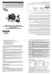
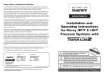
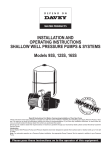
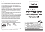
VM Series
Stainless Steel
Vertical Multistage Pumps
Installation and
Operating Instructions
In accordance with AS/NZS 60335.2.41 we are obliged to inform you that this pump is
not to be used by children or infirm persons and must not be used as a toy by children.
These Instructions must be delivered with the pump to the operator.
WARNING: Failure to follow these instructions and comply with all applicable codes
may cause serious bodily injury and/or property damage.
General
Safety
Specifications
Symbols used in the manual
Applications
Pumps for clear liquids, free of abrasives in residential,
agricultural, industrial, and other applications.
Operating Conditions
• Temperate range:
• Ambient temperature:
• Suction head:
Read this data sheet carefully before installing and starting
your pump. Pay special attention to the points concerning the
safety of the equipment.
WARNING
-15 to +120°C
up to 40°C
depends on NPSH of pump
Instructions concerning electricity
Maximum Inlet Pressure
The maximum inlet pressure is shown in the list below. But the
actual inlet pressure plus the valve close pressure of the pump
shall be lower than the maximum allowable working pressure.
Model
VM3-8 & above
Up to VM5-10
VM5-12 & above
Up to VM10-6
VM10-8 & above
VM16-2 and VM16-3
VM16-4 & above
VM32-2A to VM32-4
VM32-6 to VM32-10
VM32-12
VM65-2A
VM65-2 to VM65-3
VM65-4A and VM65-5
Up to VM90-3A
VM90-3 & above
Calls attention to a potential risk that might
affect safety.
Max. Inlet Pressure
10 bar
10 bar
15 bar
6 bar
10 bar
6 bar
10 bar
4 bar
10 bar
15 bar
4 bar
10 bar
15 bar
10 bar
15 bar
Maximum Working Pressure
Model
Up to VM3-15
VM3-17 & above
Up to VM5-16
VM5-19 and VM5-22
VM10-12
VM10-14 & above
Up to VM16-8
VM16-11 & VM16-14
Up to VM32-6
VM32-8 & above
VM65 range
VM90 range
Transport and Storage
When taking delivery of the pump, check that it has not
been damaged in transit. If anything is found wrong, take the
necessary steps with the carrier within the allowed time.
If the equipment delivered is to be installed
at a later time, store it in a dry place and
protect it from impact and outside hazards
(moisture, frost, etc.).
Handle the pump carefully so as not to alter the geometry or
alignment of the hydraulic assembly.
Product Description
The pump
Multistage vertical pump (2 to 20 stages, depending on model).
Not self-priming. Ports in line at bottom. Shaft sealing by
standardized mechanical seal.
• Flanges*
Flanges are round for all models and include screwed
companion flanges with gaskets, nuts, bolts and washers.
Curve Number
1
2
1
2
1
3
1
3
1
4
1
1
* Remove protective inserts from pump ports before fixing
flanges to pump.
The motor
The Davey VM series multi-stage pumps have been specifically
designed to be used with special TEFC flange mounted electric
motors. Typical specification for motors supplied are;
• TEFC motor with standard metric frame flange and shaft for
vertical operation. Motor and pump linked by a coupling with
safety guards.
• Protection index:
• Insulation class:
The following figure shows the limitation of pressure and
temperature, which shall be kept within the region as shown in
the figure.
P(bar)
28
24
20
16
12
8
4
0
• Single phase motors up to 2.2kW include built-in thermal
protection with automatic reset, except special dual voltage
(240/480v) motors.
• Dual voltage / larger single phase motors and three phase
motors to be wired in with a contactor incorporating quick-trip
thermal overloads.
4
3
2
1
-40
0
40
80
IP 54 (min.)
F
NOTE: • Motor sizes 0.37kW to 4.0kW are V18 / B14 small
flange mounted.
• Motor sizes 5.5kW to 22kW are V1 / B5 large
flange mounted, with special bearings.
120 t(oC)
2
FREQUENCY
SPEED
VOLTAGE*
1-PHASE
3-PHASE <4kW
3-PHASE 4kW & above
* Standard voltage; tolerance ± 10%
50Hz
2900 rpm
230V
230-400V
400V
Two standard cases for pump installations:
1. Pump in suction lift situation.
2. Pump installed with positive inlet.
Motor specifications are typical and should be confirmed at
time of order.
Assembly for pumps supplied without motors fitted
Some Davey VM series multistage pumps require special size
motor bearings built into the motor which may not allow the use
of standard flange mounted motors.
Suction Lift: Pumps operate more efficiently with positive
suction. If the pump must be installed with a suction lift,
please ensure the suction line is kept as short as possible and
the pipe diameter is at least on size or larger than the pump
inlet. Suction line should be continuously rising from the water
source to the pump in order to avoid vapour locks.
To assemble the motor onto the pump, ensure that the motor
dimensions match the pump head dimensions.
For suction lift greater than 3 metres or suction distance
greater than 50m please contact Davey.
Ensure the motor mounting face and shaft are clean and free
of debris. Lower the motor onto motor adaptor and secure
with four setscrews into the motor flange. Attach the coupling
halves onto the motor shaft and wet end shaft locating the
coupling onto the pump shaft pin. Secure the coupling with
four screws. Hand tighten only on the motor end and somewhat
tighter on the pump end to clamp the pump shaft. Ensure the
pump shaft and coupling will move as one up and down on
the motor shaft. Push coupling down as far as possible and
note it’s position. Raise the coupling up as far as possible and
mark this position. Set the coupling at the midpoint between
the top and bottom positions. Tighten all four coupling screws
evenly (tighten M6 coupling screws to 14Nm or M10 coupling
screws to 36Nm). Rotate the shaft and ensure it is free and
not rubbing. Run the pump for a short period and recheck the
pump still is free to rotate without interference.
Positive Inlet: Recommended installation for efficient pumping.
Pumping direct from town water supply
must be in compliance with local
regulations.
Install the pump in a place that is easy to reach, protected from
frost, and as close as possible to the place from which water is
drawn.
Install the pump on a foundation block at least 100mm high and
attach via the holes for 12mm dia. studs. For heavy pumps,
provide a point of attachment above the pump centre line.
Place an insulating material (cork or reinforced rubber) under
the concrete block to avoid transmitting noise and vibrations to
the rest of the installation. Before final tightening of the anchor
bolts, make sure that the pump centreline is quite vertical; use
shims if necessary.
NOTE: Disconnect pump from power
before undertaking ANY servicing or
clearance checks on the pump.
The altitude of the installation and the
water temperature reduce the suction
capabilities of the pump.
Installation
Housing your Pump
To protect your pump from the weather, make sure the cover
provided is both water proof, frost free and has adequate
ventilation.
The pump should be vertically mounted on a firm dry base
allowing for drainage, to avoid damage to flooring.
Altitude & Temperature vs Loss of Head
Altitude
Loss of head
0m
0m
500m
0.60m
1000m
1.15m
1500m
1.70m
2000m
2.20m
2500m
2.65m
3000m
3.20m
Temperature
20°C
30°C
40°C
50°C
60°C
70°C
80°C
90°C
100°C
Loss of head
0.20m
0.40m
0.70m
1.20m
1.90m
3.10m
4.70m
7.10m
10.30m
The pump must be placed in a well drained
location or in a pan connected to a drain to
avoid water damage from leaking fittings,
seals etc.
Hydraulic connections
The diameter of the suction piping must never be less than that
of the pump.
Limit the length of the suction pipe and avoid all features that
cause losses of head (tapers, bends, etc.).
The suction pipe, which should slope upward slightly, must be
fully airtight, especially at fittings.
If a rigid pipe is used, provide supports or collars so that the
pump does not bear the weight of the pipe.
An arrow on the pump casing shows the direction of fluid flow.
Carefully seal the pipes with thread tape.
Electrical connections
The electrical connections and checks
must be made by a qualified electrician and
comply with applicable local standards.
WARNING: Some insects, such as small ants,
find electrical devices attractive for various
reasons. If your pump enclosure is susceptible
to insect infestation you should implement a
suitable pest control plan.
continued overleaf...
3
Dry-running protection
To avoid accidental loss of prime of the pump, we recommend
protecting it with a suitable device.
Refer to the motor data plate for its electrical characteristics
(frequency, voltage, nominal current).
The three-phase and single phase dual voltage motors must
be protected by a circuit-breaker or magnetic contactor with
overload set to the current marked on the motor data plate.
Provide a fused disconnecting or isolating switch, in
compliance with local standards.
The electric connections should be made as shown in the
diagrams inside the cover of the motor terminal box.
Check direction of rotation
Turn the coupling by hand to make sure that it turns freely,
without sticking.
Power up the motor by briefly pressing the circuit-breaker and
check that it turns in the direction indicated by the arrow on the
pump head.
DO NOT FORGET TO CONNECT THE EARTH.
If not, for three phase, interchange two of the three active wires
on the motor terminal block or circuit-breaker. Note that this
work must be carried out by a suitably qualified person.
A connection error will damage the motor.
The power cable must never touch the pipe
or the pump; make sure that it is protected
from any moisture.
For single phase check wiring diagram in terminal box lid.
NOTE: Direction of rotation of the motor diagram is when
viewed from the motor shaft end.
The orientation of the motor can be changed a quarter turn by
removing the motor attachment screws (if necessary, remove
the coupling guards) and turning the motor to the desired
position.
Refit the screws and the coupling guards.
The standard three phase electric motors used with pumps can
be connected to a frequency converter.
Strictly follow the directions given by the manufacturer’s
data sheet.
The converter must not generate a peak change of voltage dV/
dt in excess of 500 V/ms, since this would cause noise and
damage the motor winding.
If it does, place an LC (inductance-capacitance) filter between
the converter and the motor.
Starting up
The pump must not be operated in a noflow condition (discharge valve closed) for
more than 5 minutes with cold water
(< 40oC) or more than 2 minutes for hot
water.
We recommend establishing a minimum flow of about 10% of
the rated capacity of the pump, to avoid the formation of a gas
pocket at the top of the pump. Open the discharge valve to
start the pump. Use a pressure gauge to check the stability of
the discharge pressure; if it is unstable, bleed the pump again
or repeat the priming operation.
Check that the current draw does not exceed the value marked
on the motor data plate.
Starting Up
Filling or Priming
Servicing
Never operate the pump dry, even briefly.
No special servicing is required in normal operation. Always
keep the pump perfectly clean, particularly the motor and motor
fan cover.
Pump in flooded suction installation
• Close the discharge valve.
• Unscrew the bleed plug fitted to pump head.
• Open the suction valve progressively and completely fill the
pump.
• Screw the bleed plug back in only after water flows out and
all air has been eliminated.
For a prolonged shutdown, if there is no risk of frost, it is best
not to drain the pump.
To avoid blocking of the shaft and the hydraulic system, in
frosty periods, empty the pump by removing the drain plug and
the air bleed plug.
• Screw the 2 plugs back in loosely, without tightening them.
In a hot-water application, a stream
of water may escape from the bleed
port. Do what is necessary to
protect persons and the motor.
Motors without grease fittings
The bearings are greased for life and so need no lubrication.
Mechanical seal
The mechanical seal needs no servicing in operation.
It must never be allowed to operate dry.
Pump with suction lift
• Close the discharge valve.
• Open the suction valve if fitted.
• Remove the bleed plug on the main body of the pump.
• Unscrew the bottom drain and priming plug on the pump
casing four or five turns.
• Put a funnel into the bleed plug and slowly and completely
fill the pump and the suction pipe.
• When water flows out and all air has been eliminated, filling
is complete.
• Screw the bleed plug and the bottom drain and priming plug
back in.
The following must be done in addition after the filling plug has
been screwed back in:
• Start the motor briefly.
• Unscrew the prime plug again and top up the water in the
pump.
• If necessary, repeat this operation until all air is expelled
from pump.
4
Trouble Shooting
Switch the pump OFF before doing any work on it
SYMPTOM
CAUSE
REMEDIES
PUMP TURNS BUT NO
a) The internal parts are
a)
DISCHARGE FLOW
obstructed by foreign bodies
b) Suction pipe obstructed
b)
c) Air leaks in via suction pipe
c)
d) The pump has lost its prime
d)
e) The suction lift is too high,
e)
this is generally accompanied by cavitation noise
f) The pump turns the wrong way
f)
g) The supply voltage to the
g)
motor is too low
h) No incoming water flow h)
(flooded suction)
THE PUMP VIBRATES
a) Loose on its foundation
b) Foreign bodies obstructing
the pump
c) Pump is hard to turn
d) Incorrect electrical connection
a) b) c) d) e) The motor fails to run at its
normal speed (foreign bodies,
defective power supply, etc.)
The motor is faulty
Pump poorly filled
The motor turns the wrong
way (three phase only)
Suction leak
Clean all the pipes. If suction valve fitted, ensure it is fully open.
Check the tightness of the suction pipe line, up to the pump, and
make it airtight.
Fill the pump to re-prime. Check that the foot valve seals and
does not leak.
Suction height too great (check the NPSH of the pump installed).
Install the pump closer to the water.
Check direction of rotation in main section.
Check the voltage on the terminals of the motor and the crosssections of the conductors.
Check water tank or mains for water.
a) Check the nuts of the stud bolts and tighten them fully.
b) Dismantle the pump and clean it.
c) Check that the pump turns freely without abnormal sticking.
d) Check the connections to the pump.
THE MOTOR OVERHEATS
a) Voltage too low:
a)
b) Foreign bodies obstructing
b)
the pump
c) Ambient temperature above
c)
+40°C
THE PUMP DELIVERS
INSUFFICIENT PRESSURE
Dismantle the pump and clean it.
Check the voltage on the terminals of the motor; it should be
within ±10% of the rated voltage.
Dismantle the pump and clean it.
The motor is designed to operate at an ambient temperature of
not more than +40°C.
a) Dismantle the pump and correct the problem.
b) Replace it.
c) Fill the pump and bleed until there are no more air bubbles.
d) Alternate two wires on the motor terminal block or the
circuit-breaker to reverse the direction of rotation.
e) Check and reseal fittings.
THE MOTOR TRIPS OUT
a) The setting of the thermal
a) Check the current with an ammeter, or set to the current rating
relay is too low (three-phase marked on the motor data plate.
motor)
b) The voltage is too low
b) Check that the conductor cross-sections of the power cable are
adequate.
c) One phase is open-circuit
c) Check it and correct where required.
d) The thermal relay of the circuit-
d) Replace it.
breaker is faulty
e) Ambient temperature above
e) The motor is designed to operate at an ambient temperature of +40°C
not more than +40°C.
THE FLOW IS IRREGULAR a) The suction height is
a)
exceeded
b) The diameter of the suction b)
pipe is smaller than that of
the pump
c) The strainer and suction pipe
c)
are partially obstructed
Reread the installation conditions and recommendations in these instructions.
The suction pipe must be sized to suit the application and be
at least the same diameter as the pump suction port.
5
Remove and clean.
Davey® Repair or Replacement Guarantee
In the unlikely event in Australia or New Zealand that this Davey product develops any malfunction
within two years of the date of original purchase due to faulty materials or manufacture, Davey will at
our option repair or replace it for you free of charge, subject to the conditions below.
Should you experience any difficulties with your Davey product, we suggest in the first instance that
you contact the Davey Dealer from which you purchased the Davey product. Alternatively you can
phone our Customer Service line on 1300 367 866 in Australia, or 0800 654 333 in New Zealand, or
send a written letter to Davey at the address listed below. On receipt of your claim, Davey will seek to
resolve your difficulties or, if the product is faulty or defective, advise you on how to have your Davey
product repaired, obtain a replacement or a refund.
Your Davey Two Year Guarantee naturally does not cover normal wear or tear, replacement of product
consumables (i.e. mechanical seals, bearings or capacitors), loss or damage resulting from misuse
or negligent handling, improper use for which the product was not designed or advertised, failure to
properly follow the provided installation and operating instructions, failure to carry out maintenance,
corrosive or abrasive water or other liquid, lightning or high voltage spikes, or unauthorized persons
attempting repairs. Where applicable, your Davey product must only be connected to the voltage
shown on the nameplate.
Your Davey Two Year Guarantee does not cover freight or any other costs incurred in making a claim.
Please retain your receipt as proof of purchase; you MUST provide evidence of the date of original
purchase when claiming under the Davey Two Year Guarantee.
Davey shall not be liable for any loss of profits or any consequential, indirect or special loss, damage or
injury of any kind whatsoever arising directly or indirectly from Davey products. This limitation does not
apply to any liability of Davey for failure to comply with a consumer guarantee applicable to your Davey
product under the Australian or New Zealand legislation and does not affect any rights or remedies that
may be available to you under the Australian or New Zealand Consumer Legislation.
In Australia, you are entitled to a replacement or refund for a major failure and for compensation for
any other reasonably foreseeable loss or damage. You are also entitled to have the goods repaired or
replaced if the goods fail to be of acceptable quality and the failure does not amount to a major failure.
Should your Davey product require repair or service after the guarantee period; contact your nearest
Davey Dealer or phone the Davey Customer Service Centre on the number listed below.
For a complete list of Davey Dealers visit our website (davey.com.au) or call:
AUSTRALIA
NEW ZEALAND
Customer Service Centre
6 Lakeview Drive,
Scoresby, Australia 3179
Ph:
1300 367 866
Fax:
1300 369 119
Website:davey.com.au
Customer Service Centre
7 Rockridge Avenue,
Penrose, Auckland 1061
Ph:
0800 654 333
Fax:
09 527 7654
Website:daveynz.co.nz
Davey Water Products Pty Ltd
Member of the GUD Group
ABN 18 066 327 517
® Davey is a registered trade mark of Davey Water Products Pty Ltd.
© Davey Water Products Pty Ltd 2011.
P/N 400584-5 supersedes P/N 400584-4
* Installation and operating instructions are included with the product when purchased new.
They may also be found on our website.