1
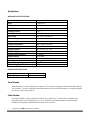
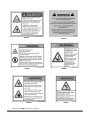
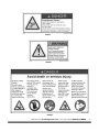
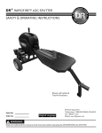
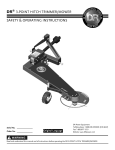
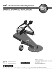
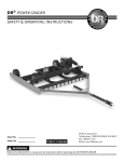
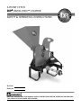
3-POINT HITCH
DR® RAPID-FEED™ CHIPPER
SAFETY & OPERATING INSTRUCTIONS
Serial No.
Order No.
READ AND UNDERSTAND THIS MANUAL AND ALL INSTRUCTIONS BEFORE OPERATING OR SERVICING
THIS 3-POINT HITCH DR RAPID FEED CHIPPER.
Congratulations on your purchase of a new 3-POINT HITCH DR RAPID FEED CHIPPER!
We have done our utmost to ensure that your 3-POINT HITCH DR RAPID FEED CHIPPER will be one of the
most trouble-free and satisfying pieces of equipment you have ever owned. Please let us know of any
questions you may have. We want to answer them as quickly as possible. When you do call, please have your
order number handy. For technical assistance, please contact us at www.DRpower.com or call Toll-Free 1-800DR-OWNER (376-9637) and one of our Technical Support Representatives will be happy to help you. We also
hope to hear from you on how much you like your new helper.
In addition, please tell your friends about your new 3-POINT HITCH DR RAPID FEED CHIPPER! Having DR
Owners spread the word about our products and our way of doing business is the best advertising we can
have, and the best way to help us provide even better service in the years to come.
Thanks once again!
for all of us at
DR Power Equipment
Sales Manager
COPYRIGHT
©2008 Country Home Products, Inc. All rights reserved.
DR® Power Equipment
A division of Country Home Products®
75 Meigs Road
Vergennes, VT 05491
Toll-free phone: 1-800-DR-OWNER (376-9637)
Fax: 1-802-877-1213
Web site: www.dr-owner.com
ii
3-POINT HITCH DR® RAPID-FEED™ CHIPPER
Table of Contents
CHAPTER 1 ..........................................................................................................................................1
INTRODUCING THE 3-POINT HITCH DR RAPID FEED CHIPPER...........................................1
Conventions used in this manual.................................................................................................1
Specifications ................................................................................................................................2
Serial Number ...............................................................................................................................2
Order Number...............................................................................................................................2
CHAPTER 2 ..........................................................................................................................................3
GENERAL SAFETY RULES ............................................................................................................3
Labels ..........................................................................................................................................3
Protecting Yourself and Those Around You.................................................................................6
Safety for Children and Pets..........................................................................................................7
General Safety................................................................................................................................7
Transportation Safety....................................................................................................................9
Additional Information and Potential Changes .........................................................................10
CHAPTER 3 ........................................................................................................................................11
SETTING UP YOUR 3-POINT HITCH DR RAPID FEED CHIPPER ...........................................11
3-POINT HITCH DR RAPID FEED CHIPPER Controls and Features .......................................11
Unpacking the 3-POINT HITCH DR RAPID FEED CHIPPER....................................................12
Attaching the Hopper Assembly.................................................................................................14
Attaching the Discharge Chute...................................................................................................14
Attaching the 3-POINT HITCH DR RAPID FEED CHIPPER......................................................15
Calculating length of PTO Shaft needed ....................................................................................16
Modifying the PTO Shaft-if required...........................................................................................17
Attaching the PTO Shaft to the Tractor and Chipper.................................................................19
CHAPTER 4 ........................................................................................................................................21
OPERATING YOUR 3-POINT HITCH DR RAPID FEED CHIPPER ...........................................21
Starting the Chipper ....................................................................................................................21
Operation Notes..........................................................................................................................22
Processing Material.....................................................................................................................22
To Free a Jammed Flywheel ........................................................................................................24
CHAPTER 5 ........................................................................................................................................25
MAINTAINING THE 3-POINT HITCH DR RAPID FEED CHIPPER..........................................25
Regular Maintenance Check List ................................................................................................25
Grease Fittings ............................................................................................................................26
Removing, Replacing and Adjusting the Drive Belt ...................................................................27
Removing, Replacing and Adjusting the Chipper Knife and Wear Plate...................................29
VISUAL INSPECTION OF THE CHIPPER KNIFE BEFORE EACH USE ....................................29
VISUAL INSPECTION OF THE CHIPPER KNIFE AND WEAR PLATE EVERY 8-10 HOURS ...30
Removing and Replacing the Wear Plate ...................................................................................32
Checking and Adjusting the Knife to Wear Plate Gap................................................................32
Chipper Knife Sharpening ...........................................................................................................34
Wear Plate Sharpening................................................................................................................35
End of Season and Storage.........................................................................................................36
CHAPTER 6 ........................................................................................................................................37
TROUBLESHOOTING ................................................................................................................37
Troubleshooting Table ................................................................................................................37
CONTACT US AT www.DRpower.com or CALL TOLL FREE 1-800-DR-OWNER
iii
CHAPTER 7 ........................................................................................................................................39
CHIPPER ACCESSORIES ............................................................................................................39
Extended Top-Discharge Chute ..................................................................................................39
CHAPTER 8 ........................................................................................................................................42
PARTS LIST AND SCHEMATIC DIAGRAMS..............................................................................42
Parts List - 3-POINT HITCH DR RAPID FEED CHIPPER ..........................................................42
Schematic - 3-POINT HITCH DR RAPID FEED CHIPPER.........................................................43
Parts List – Chipper Basic ...........................................................................................................44
Schematic – Chipper Basic .........................................................................................................45
Parts List – Hopper Assembly ....................................................................................................46
Schematic – Hopper Assembly...................................................................................................47
Parts List – Extended Top Discharge Chute...............................................................................48
Schematic – Extended Top Discharge Chute .............................................................................49
Notes: ........................................................................................................................................50
Daily Checklist for the 3-POINT HITCH DR RAPID FEED CHIPPER........................................52
iv
3-POINT HITCH DR® RAPID-FEED™ CHIPPER
CHAPTER 1
INTRODUCING THE 3-POINT HITCH DR RAPID FEED
CHIPPER
This manual will help you set up and safely operate your new 3-POINT HITCH DR RAPID FEED
CHIPPER. Careful adherence to the safety and operating instructions in this manual will ensure many
years of productive use.
Please let us know of any questions you may have. We want to answer them as quickly as possible.
When you do call, please have your order number handy. For technical assistance, please contact us at
www.DRpower.com or call Toll-Free 1-800-DR-OWNER (376-9637) and one of our Technical Support
Representatives will be happy to help you.
THIS INDICATES A HAZARDOUS SITUATION, WHICH, IF NOT FOLLOWED, WILL RESULT IN DEATH
OR SERIOUS INJURY.
THIS INDICATES A HAZARDOUS SITUATION, WHICH, IF NOT AVOIDED, COULD RESULT IN DEATH
OR SERIOUS INJURY.
THIS INDICATES A HAZARDOUS SITUATION, WHICH, IF NOT AVOIDED, COULD RESULT IN MINOR
OR MODERATE INJURY.
THIS INFORMATION IS IMPORTANT IN THE PROPER USE OF YOUR MACHINE. FAILURE TO FOLLOW
THIS INSTRUCTION COULD RESULT IN DAMAGE TO YOUR MACHINE OR PROPERTY.
Conventions used in this manual
Tip: This is a helpful hint to guide you in getting the most out of your 3-POINT HITCH DR RAPID FEED
CHIPPER.
Tools Needed: This indicates you will need a special tool to perform a maintenance function on your
Chipper.
NOTE: This information may be helpful to you.
If you are ever unsure about an action you are about to take, don’t do it. Contact us at www.DRpower.com or
call DR Power Equipment’s toll-free support at 1-800-DR-OWNER (376-9637) for help or information.
CONTACT US AT www.DRpower.com or CALL TOLL FREE 1-800-DR-OWNER
1
Specifications
MECHANICAL SPECIFICATIONS
Tractor Horsepower
Category 1 – 65 HP Max.
Drive
Tractor PTO
PTO Speed
540 RPM
PTO Shaft Extension Sheave
14" – 3 Groove 3V
Chipping Capacity
4-1/2"
Rotor Speed
2,071 RPM
Rotor Pulley
3.65" DIA., 3 Groove 3V
Number of Chipper Knives
1
Chipper Knife Size
6-1/4" X 2" X 3/8"
Chipper Knife Material
Heat Treated Tool Steel
Adjustable Knife Wear Plate
Yes
Chipper Flywheel
16-1/2" DIA., 3/4" THK
Flywheel Weight
Chipper Housing Material
Hopper Material
Belt
Belt Adjustment
Hopper Opening at Top
Chipper Weight w/PTO Shaft
55 LBS.
7 GA Steel
14 GA Steel
3V-3 Groove X 60"
Spring Loaded Idler Pulley
22-1/2" X 29"
295 lbs.
SHIPPING SPECIFICATIONS
Shipping Dimensions
Shipping Weight
54" L x 46" W x 46" H
382 lbs
Serial Number
A Serial Number is used to identify your machine. The number is located on the Serial Number Label on
your machine. For your convenience and ready reference, enter the Serial Number in the space provided
on the front cover of this manual.
Order Number
An Order Number is used to check and maintain your order history. The number is located on the
upper left portion of your packing slip. For your convenience and ready reference, enter the Order
Number in the space provided on the front cover of this manual.
2
3-POINT HITCH DR® RAPID-FEED™ CHIPPER
CHAPTER 2
GENERAL SAFETY RULES
•
READ THIS SAFETY & OPERATING MANUAL AND YOUR TRACTOR OWNERS MANUAL BEFORE
YOU USE THE 3-POINT HITCH DR RAPID FEED CHIPPER. BECOME FAMILIAR WITH THE
OPERATION AND SERVICE RECOMMENDATIONS TO ENSURE THE BEST PERFORMANCE FROM
YOUR MACHINE.
•
THOROUGHLY INSPECT THE AREA IN WHICH YOU WILL BE WORKING AND REMOVE ALL
FOREIGN OBJECTS. LOOK FOR ROPE, WIRE, ETC., AND REMOVE THESE OBJECTS BEFORE
CHIPPING. INSERTING THESE OBJECTS INTO THE CHIPPER HOPPER COULD DAMAGE THE
MACHINE AND/OR CAUSE INJURY.
•
THIS IS A HIGH-POWERED MACHINE, WITH MOVING PARTS OPERATING WITH HIGH ENERGY
AT HIGH SPEEDS. YOU MUST USE PROPER CLOTHING AND SAFETY GEAR WHEN OPERATING
THIS MACHINE TO PREVENT OR MINIMIZE THE RISK OF SEVERE INJURY. THIS MACHINE CAN
CRUSH, GRIND, CUT, AND SEVER PARTS OF YOUR BODY IF THEY ENTER THE INLET OR
DISCHARGE AREA OF YOUR CHIPPER.
Labels
Your 3-POINT HITCH DR RAPID FEED CHIPPER carries prominent labels as reminders for its proper
and safe use. Shown below are copies of all the safety and operation labels that appear on the
equipment. Take a moment to study them and make a note of their location on your 3-POINT HITCH
DR RAPID FEED CHIPPER as you assemble and before you operate the unit. Replace damaged or
missing safety and operation labels immediately.
#241801
CONTACT US AT www.DRpower.com or CALL TOLL FREE 1-800-DR-OWNER
3
#241811
#248821
#241831
4
3-POINT HITCH DR® RAPID-FEED™ CHIPPER
#227391
#248811
#248831
#248791
#250581
#248841
CONTACT US AT www.DRpower.com or CALL TOLL FREE 1-800-DR-OWNER
5
Protecting Yourself and Those Around You
THIS IS A HIGH-POWERED MACHINE, WITH MOVING PARTS OPERATING WITH HIGH ENERGY AT
HIGH SPEEDS. YOU MUST OPERATE THE MACHINE SAFELY. UNSAFE OPERATION CAN CREATE A
NUMBER OF HAZARDS FOR YOU, AS WELL AS ANYONE ELSE IN THE NEARBY AREA. ALWAYS TAKE
THE FOLLOWING PRECAUTIONS WHEN USING THIS MACHINE:
•
ALWAYS WEAR PROTECTIVE GOGGLES OR SAFETY GLASSES WITH SIDE SHIELDS WHILE
CHIPPING TO PROTECT YOUR EYES FROM POSSIBLE THROWN DEBRIS.
•
AVOID WEARING LOOSE CLOTHING OR JEWELRY, WHICH CAN CATCH ON MOVING PARTS OR
THE MATERIAL FED INTO THE CHIPPER HOPPER.
•
WE RECOMMEND WEARING GLOVES WHILE CHIPPING. BE SURE YOUR GLOVES FIT PROPERLY
AND DO NOT HAVE LOOSE CUFFS OR DRAWSTRINGS.
•
WEAR SHOES WITH NON-SLIP TREADS WHEN USING YOUR CHIPPER. IF YOU HAVE SAFETY
SHOES, WE RECOMMEND WEARING THEM. DO NOT USE THE MACHINE WHILE BAREFOOT OR
WEARING OPEN SANDALS.
•
WEAR LONG PANTS WHILE OPERATING THE 3-POINT HITCH DR RAPID FEED CHIPPER.
•
USE EAR PROTECTORS OR EAR PLUGS RATED FOR AT LEAST 20 DBA TO PROTECT YOUR
HEARING.
•
NEVER ALLOW PEOPLE WHO ARE UNFAMILIAR WITH THESE INSTRUCTIONS TO USE THE
CHIPPER. ALLOW ONLY RESPONSIBLE INDIVIDUALS WHO ARE FAMILIAR WITH THESE RULES OF
SAFE OPERATION TO USE YOUR MACHINE.
•
NEVER PLACE YOUR HANDS, FEET, OR ANY PART OF YOUR BODY IN THE CHIPPER HOPPER,
DISCHARGE OPENING, OR NEAR OR UNDER ANY MOVING PART WHILE THE MACHINE IS
RUNNING. KEEP AREA OF DISCHARGE CLEAR OF PEOPLE, ANIMALS, BUILDINGS, GLASS, OR
ANYTHING ELSE THAT WILL OBSTRUCT CLEAR DISCHARGE, CAUSE INJURY, OR DAMAGE. WIND
CAN ALSO CHANGE DISCHARGE DIRECTION, SO BE AWARE. IF IT BECOMES NECESSARY TO
PUSH MATERIAL INTO THE CHIPPER HOPPER, USE A SMALL DIAMETER STICK, NOT YOUR
HANDS.
•
KEEP BYSTANDERS 100 FEET AWAY FROM YOUR WORK AREA AT ALL TIMES. WOOD CHIPS EXIT
THE CHIPPER AT GREAT SPEEDS. TO BE SAFE, DO NOT OPERATE THE MACHINE NEAR SMALL
CHILDREN OR PETS, AND NEVER ALLOW CHILDREN TO OPERATE THE CHIPPER. DISENGAGE
THE PTO AND STOP THE TRACTOR ENGINE WHEN ANOTHER PERSON OR PET APPROACHES.
•
NEVER USE THE MACHINE WITHOUT ENSURING THAT ALL GUARDS AND SHIELDS ARE IN
PLACE, INCLUDING THE CHIPPER HOPPER, DISCHARGE CHUTE AND BLOWBACK SHIELD.
•
ALWAYS OPERATE THE MACHINE FROM THE OPERATOR ZONE (SEE CHAPTER 4). NEVER PASS
OR STAND ON THE DISCHARGE SIDE OF THE MACHINE WHEN THE TRACTOR ENGINE IS
RUNNING OR THE FLYWHEEL IS TURNING.
•
NEVER TRANSPORT THE CHIPPER WITH THE PTO ENGAGED AND THE FLYWHEEL TURNING.
6
3-POINT HITCH DR® RAPID-FEED™ CHIPPER
•
CLEAR THE AREA OF OBJECTS SUCH AS WIRE AND ROPE, ETC. INSERTING THESE OBJECTS INTO
THE CHIPPER HOPPER COULD DAMAGE THE FLYWHEEL AND/OR CAUSE INJURY.
•
NEVER, UNDER ANY CONDITIONS, REMOVE, BEND, CUT, FIT, WELD, OR OTHERWISE ALTER
STANDARD PARTS ON THE 3-POINT HITCH DR RAPID FEED CHIPPER. THIS INCLUDES ALL
SHIELDS AND GUARDS. MODIFICATIONS TO YOUR MACHINE COULD CAUSE PERSONAL
INJURIES AND PROPERTY DAMAGE AND WILL VOID YOUR WARRANTY.
Safety for Children and Pets
TRAGIC ACCIDENTS CAN OCCUR IF THE OPERATOR IS NOT ALERT TO THE PRESENCE OF CHILDREN
AND PETS. CHILDREN ARE OFTEN ATTRACTED TO THE MACHINE AND THE CHIPPING ACTIVITY.
NEVER ASSUME THAT CHILDREN WILL REMAIN WHERE YOU LAST SAW THEM. ALWAYS FOLLOW
THESE PRECAUTIONS:
•
KEEP CHILDREN AND PETS AT LEAST 100 FEET FROM THE WORKING AREA AND UNDER THE
WATCHFUL CARE OF A RESPONSIBLE ADULT.
•
BE ALERT AND TURN THE MACHINE OFF IF CHILDREN OR PETS ENTER THE WORK AREA.
•
NEVER ALLOW CHILDREN TO OPERATE THE 3-POINT HITCH DR RAPID FEED CHIPPER.
General Safety
OPERATING THIS CHIPPER SAFELY IS NECESSARY TO PREVENT OR MINIMIZE THE RISK OF DEATH
OR SERIOUS INJURY. UNSAFE OPERATION CAN CREATE A NUMBER OF HAZARDS FOR YOU.
ALWAYS TAKE THE FOLLOWING PRECAUTIONS WHEN OPERATING THIS CHIPPER:
•
THIS MACHINE IS DESIGNED TO OPERATE AT 540 RPM ONLY! NEVER OPERATE THE MACHINE
AT A FASTER SPEED; DOING SO CAN CAUSE SERIOUS INJURY TO THE OPERATOR OR
BYSTANDERS AND COULD CAUSE DAMAGE TO THE MACHINE THAT IS NOT COVERED UNDER
WARRANTY.
•
THE DR 3-POINT HITCH CHIPPER MUST BE OPERATED WITH THE WEIGHT OF THE MACHINE
ON THE GROUND. OPERATING THE MACHINE WHILE IT IS OFF THE GROUND CAN RESULT IN
INJURY TO YOURSELF OR OTHERS, OR CAN CAUSE DAMAGE TO THE MACHINE WHICH IS NOT
COVERED UNDER WARRANTY.
•
KEEP IN MIND THAT THE OPERATOR OR USER IS RESPONSIBLE FOR ACCIDENTS OR HAZARDS
OCCURRING TO OTHER PEOPLE, THEIR PROPERTY, AND THEMSELVES.
CONTACT US AT www.DRpower.com or CALL TOLL FREE 1-800-DR-OWNER
7
•
YOUR 3-POINT HITCH DR RAPID FEED CHIPPER IS A POWERFUL TOOL, NOT A PLAYTHING.
EXERCISE EXTREME CAUTION AT ALL TIMES. THE DESIGN OF THIS MACHINE IS TO CHIP
WOOD. DO NOT USE IT FOR ANY OTHER PURPOSE.
•
KNOW HOW TO STOP THE CHIPPER QUICKLY BY DISENGAGING THE PTO AND SHUTTING
DOWN THE TRACTOR.
•
OPERATE THIS MACHINE ON A LEVEL SURFACE ONLY. NEVER OPERATE YOUR UNIT ON A
SLIPPERY, WET, MUDDY, OR ICY SURFACE. EXERCISE CAUTION TO AVOID SLIPPING OR
FALLING.
•
KEEP YOUR FACE AND BODY BACK FROM THE CHIPPER HOPPER TO AVOID ACCIDENTAL
BOUNCE BACK OF ANY MATERIAL.
•
WHEN FEEDING MATERIAL INTO THE CHIPPER HOPPER, BE EXTREMELY CAREFUL THAT PIECES
OF METAL, ROCKS, OR OTHER FOREIGN OBJECTS ARE NOT INCLUDED. PERSONAL INJURY OR
DAMAGE TO THE MACHINE COULD RESULT.
•
WHENEVER YOU LEAVE THE OPERATING POSITION OR IF YOU HAVE TO REMOVE PROCESSED
MATERIAL, LEAVES, OR DEBRIS FROM THE MACHINE, ALWAYS DISENGAGE THE PTO, SHUT
DOWN THE TRACTOR ENGINE, REMOVE THE KEY, WAIT FOR ALL MOVING PARTS TO COME TO
A COMPLETE STOP, DISCONNECT THE PTO SHAFT FROM THE TRACTOR, THEN WAIT 5
MINUTES BEFORE REMOVING PROCESSED MATERIAL, LEAVES, OR DEBRIS FROM THE
MACHINE.
•
IF THE CUTTING MECHANISM STRIKES A FOREIGN OBJECT OR IF YOUR MACHINE SHOULD
START MAKING AN UNUSUAL NOISE OR VIBRATION, IMMEDIATELY DISENGAGE THE PTO,
SHUT DOWN THE TRACTOR ENGINE, REMOVE THE KEY, WAIT FOR ALL MOVING PARTS TO
COME TO A COMPLETE STOP, DISCONNECT THE PTO SHAFT FROM THE TRACTOR, THEN WAIT
5 MINUTES BEFORE INSPECTING FOR CLOGGING OR DAMAGE. VIBRATION IS GENERALLY A
WARNING OF TROUBLE. CLEAN AND REPAIR AND/OR REPLACE DAMAGED PARTS.
•
NEVER TAMPER WITH SAFETY DEVICES. CHECK THEIR PROPER OPERATION REGULARLY.
•
STAY ALERT FOR HIDDEN HAZARDS OR TRAFFIC. NEVER CARRY PASSENGERS ON YOUR
MACHINE.
•
NEVER OVERLOAD OR ATTEMPT TO CHIP MATERIAL BEYOND THE MANUFACTURER’S
RECOMMENDATION; SEE CHAPTER 4. PERSONAL INJURY OR DAMAGE TO THE MACHINE
COULD RESULT.
•
WHILE USING THE 3-POINT HITCH DR RAPID FEED CHIPPER, DON'T HURRY OR TAKE THINGS
FOR GRANTED. WHEN IN DOUBT ABOUT THE EQUIPMENT OR YOUR SURROUNDINGS, STOP
THE MACHINE AND TAKE THE TIME TO LOOK THINGS OVER.
•
NEVER OPERATE THE MACHINE WHEN UNDER THE INFLUENCE OF ALCOHOL, DRUGS, OR
MEDICATION.
•
USE THE MACHINE ONLY IN DAYLIGHT.
•
KEEP ALL NUTS AND BOLTS TIGHT AND KEEP THE EQUIPMENT IN GOOD OPERATING
CONDITION.
8
3-POINT HITCH DR® RAPID-FEED™ CHIPPER
•
YOUR 3-POINT HITCH DR RAPID FEED CHIPPER IS DRIVEN BY A PTO SHAFT THAT TRANSFERS
POWER FROM YOUR TRACTOR. A PTO SHAFT IS EXTREMELY DANGEROUS AND CAN CAUSE
SERIOUS INJURY OR DEATH. READ AND UNDERSTAND ALL OF THE SAFETY AND OPERATING
INSTRUCTIONS MANUAL THAT CAME WITH YOUR PTO SHAFT.
•
NO LIST OF WARNINGS AND CAUTIONS CAN BE ALL-INCLUSIVE. IF SITUATIONS OCCUR THAT
ARE NOT COVERED BY THIS MANUAL, THE OPERATOR MUST APPLY COMMON SENSE AND
OPERATE THIS CHIPPER IN A SAFE MANNER. CONTACT US AT WWW.DRPOWER.COM OR CALL
1 (800) DR-OWNER (376-9637) FOR ASSISTANCE.
Transportation Safety
•
BEFORE TRANSPORTING, BE CERTAIN THE DR 3-POINT HITCH CHIPPER IS CORRECTLY AND
SECURELY ATTACHED TO YOUR TRACTOR AND THE SAFETY CHAINS OF THE PTO ARE IN PLACE.
•
MAKE SURE THE DR 3-POINT HITCH CHIPPER IS RAISED HIGH ENOUGH TO CLEAR ALL
OBSTACLES DURING TRANSPORTATION.
•
NEVER TRANSPORT THE MACHINE FOR LONG DISTANCES.
•
NEVER ALLOW ANYONE TO RIDE ON THE DR 3-POINT HITCH CHIPPER.
•
NEVER TRANSPORT ANYTHING ON THE MACHINE.
•
NEVER TRANSPORT THE DR 3-POINT HITCH CHIPPER WITH THE PTO ENGAGED.
•
OBEY LOCAL, STATE, AND FEDERAL REGULATIONS WHEN TRANSPORTING THE MACHINE ON
PUBLIC ROADS AND HIGHWAYS.
•
ALLOW FOR ADDED LENGTH IN DRIVING SITUATIONS, E.G., WHEN TURNING, PARKING, AND
CROSSING INTERSECTIONS.
•
ADJUST YOUR TRANSPORTATION SPEED FOR TERRAIN AND CONDITIONS.
•
USE CAUTION WHEN BACKING OR TURNING. BE AWARE OF THE LARGE TURNING RADIUS
REQUIRED WITH THE 3-POINT HITCH DR RAPID FEED CHIPPER ATTACHED TO YOUR TRACTOR.
CONTACT US AT www.DRpower.com or CALL TOLL FREE 1-800-DR-OWNER
9
Additional Information and Potential Changes
DR Power Equipment reserves the right to discontinue, change, and improve its products at any time
without notice or obligation to the purchaser. The descriptions and specifications contained in this
manual were in effect at printing. Equipment described within this manual may be optional. Some
illustrations may not be applicable to your machine.
10
3-POINT HITCH DR® RAPID-FEED™ CHIPPER
CHAPTER 3
SETTING UP YOUR 3-POINT HITCH DR RAPID FEED
CHIPPER
This chapter outlines unpacking and a few simple steps you will need to follow to set up your new
machine before you use it. It may be helpful to familiarize yourself with the controls and features of your
3-POINT HITCH DR RAPID FEED CHIPPER as shown in Figure 1 before beginning these procedures. If
you have any questions at all, please feel free to contact us at www.DRpower.com or call our Customer
Service Representatives at our toll free number: 1-800-DR-OWNER (376-9637).
3-POINT HITCH DR RAPID FEED CHIPPER Controls and Features
Blow-Back
Shield
Hopper
Assembly
Chipper
Knife
Wear
Plate
Discharge
Chute
Flywheel
Bearing
Chipper Knife
Access Covers
3-Groove
Sheave
Belt
Tensioner
Belt
Idler
Pulley
3-Point Hitch
Mounting Pin
3-Groove
Sheave
PTO
Bearing
Support
Leg
Belt Guard
Cover Removed for Clarity
Figure 1
CONTACT US AT www.DRpower.com or CALL TOLL FREE 1-800-DR-OWNER
11
Extended Top-Discharge
(optional Accessory)
3-Point
Hitch
Chipper
Unpacking the 3-POINT HITCH DR RAPID FEED
CHIPPER
NOTE: Unpacking the 3-POINT HITCH DR RAPID FEED
CHIPPER is a two-person job. We recommend you have an extra set
of hands available before you begin because the 3-POINT HITCH
DR RAPID FEED CHIPPER weighs 282 lbs.
Tools and Supplies Needed:
•
•
•
•
•
PTO
Shaft
Hopper
Assembly
Parts
Box
Figure 2
Discharge
Chute
Gloves
Wire Cutters
Pry Bar
Hammer
1/2" Wrench
Parts supplied on Skid (Figure 2):
•
•
•
•
Hardware
Package
•
Safety
Glasses
3-POINT HITCH DR RAPID FEED CHIPPER
Hopper Assembly
PTO Shaft Assembly(with PTO Manual)
Extended Top-Discharge Chute (if ordered, see
Chapter 7 “Chipper Accessories”)
Parts Box containing (Items below and Figure
3):
− Discharge Chute
− Safety & Operation Instructions Manual
− Hardware Package (Figure 4 and Table
below)
Safety & Operating
Instructions Manual
Figure 3
3
HARDWARE PACKAGE CONTENTS (FIGURE 4)
2
ITEM #
4
5
7
1
6
Figure 4
12
3-POINT HITCH DR® RAPID-FEED™ CHIPPER
1
2
3
4
5
6
7
DESCRIPTION
Bolt, 5/16-18 X 5-1/4"
Nylon Locknut, 5/16-18
5/16-18 x 1" Bolts
5/16" Flat Washer
Key, 1/4" X 1/4" X 1-1/4"
Knife Gap Gauge
Set Screws, 3/8-16 X 3/8"
QTY
2
8
6
12
1
1
2
•
WEAR EYE PROTECTION WHEN REMOVING THE CRATE
TOP TO PROTECT YOUR EYES FROM FLYING DEBRIS.
•
STABILIZE THE SHIPPING CONTAINER ON CLEAN FLAT
TERRAIN BEFORE ATTEMPTING TO UNPACK AND
ASSEMBLE THE CHIPPER.
•
FOR YOUR SAFETY WE RECOMMEND YOU HAVE TWO
PEOPLE FOR THE FOLLOWING PROCEDURES.
1.
Cut the Plastic Banding that is securing the Parts Box,
PTO Shaft Assembly and any Accessories that may be
strapped to the Crate (Figure 5).
2.
Remove the Parts Box, PTO Shaft Assembly and any
accessories (if ordered).
3.
Pry off the two bottom side boards that connect the
Crate top to the Pallet (Figure 6).
4.
With help from another person, lift the Crate Top from
the Pallet.
Plastic
Banding
Figure 5
Bottom
Side
Boards
Figure 6
5.
Remove the four Lag Bolts that secure the Chipper
Support Legs to the Pallet (Figure 7).
6.
With the help of another person, carefully slide the
Chipper from the shipping pallet, resting it on the
Support Legs.
Pallet
Lag Bolts
Chipper
Support
Leg
Figure 7
CONTACT US AT www.DRpower.com or CALL TOLL FREE 1-800-DR-OWNER
13
Hopper
Assembly
7.
Pull up and then out on the small end of the Hopper
Assembly to remove it from the Pallet (Figure 8).
8.
Open the Parts Box and lay out the contents of the Box
and the Hardware Package.
Compare the contents of the shipping container and the Parts
Box with the Parts Supplied list on page 12. If there are any
questions contact us at www.DRpower.com or call 1-800-DROWNER (376-9637). Do not discard the shipping materials until
you are fully satisfied with your new 3-POINT HITCH CHIPPER.
Figure 8
Attaching the Hopper Assembly
NOTE: We recommend that you have someone help you lift the
Hopper in place and support it until it is secured to the Chipper.
Hopper
Assembly
Tools Needed:
•
1.
Hopper
Hardware
Two 1/2" Wrenches
Attach the Hopper Assembly to the Chipper with six
5/16"-18 x 1" Bolts, twelve Flat Washers (one Washer
on Bolt side and one on Lock Nut side) and six Nylon
Lock Nuts (Figure 9).
NOTE: Install hardware with Bolt Head on the top side.
Figure 9
Attaching the Discharge Chute
Discharge
Chute
Tools Needed:
Bolts and
Locknuts
•
1.
Figure 10
14
3-POINT HITCH DR® RAPID-FEED™ CHIPPER
Two 1/2" Wrenches
Position the Discharge Chute as shown and secure
with two 5/16-18 x 5-1/4" Bolts and Nylon Locknuts
(Figure 10).
Attaching the 3-POINT HITCH DR RAPID FEED
CHIPPER
Upper (pivot)
Draft Arm
NOTE: The PTO Driveshaft provided with your new machine
is sized to fit a standard category 1 PTO (1-3/8" DIA.
x 6" Spline).
The PTO shaft on the tractor that is to use this
machine must rotate clockwise when viewing the PTO
from the rear of the tractor. If the PTO rotates
counterclockwise, you must have your tractor
modified by installing a gearbox to reverse the
direction of rotation.
The length of the PTO Driveshaft that is included
with your new machine may need to be modified.
See the procedure for checking the PTO Shaft length
needed and modification instructions in this chapter.
1.
Back the Tractor to the Chipper and position the Lower
Draft Arms near the Chipper Hookup Pins (Figure 11).
2.
Slide the Lower Draft Arms onto the Chipper Hookup
BEFORE PERFORMING THE FOLLOWING PROCEDURE, BE
SURE YOUR TRACTOR ENGINE IS OFF, BRAKE IS SET, AND
THE KEY REMOVED FOR SAFETY.
Lower (lifting)
Draft Arms
Figure 11
Tractor
Hitch Pin
Figure 12
Pins and secure with Tractor Hitch Pins (Figure 12).
3.
Position the Upper Draft Arm inside the Mounting
Bracket and align with the Mounting Bracket Holes
(Figure 13).
4.
Insert the Tractor Hitch Pin to secure the Upper Draft
Arm to the Chipper.
Chipper
Hookup
Pins
Upper (pivot)
Draft Arm
Tractor
Hitch Pin
Mounting
Bracket
Figure 13
Chipper
Mounting
Hole
CONTACT US AT www.DRpower.com or CALL TOLL FREE 1-800-DR-OWNER
15
End of Chipper
PTO Shaft
Calculating length of PTO Shaft needed
The PTO Shaft provided with your Chipper is 27" overall
compressed length and will work for most applications without
modifications. Before you install the PTO Shaft it is good
practice to run through the following dimension checks to
calculate optimum PTO Shaft length to determine if
modifications are needed.
End of
Tractor
PTO
Shaft
Without the PTO Shaft installed, use the table below to record
the dimensions as outlined in the following steps.
Chipper on
the Ground
Figure 14
SHAFT TO SHAFT MEASUREMENTS
End of Chipper
PTO Shaft
End of
Tractor
PTO
Shaft
Chipper lifted off Ground until
Shafts are level with each other
Figure 15
Chipper lifted all the way
off the Ground
SHAFTS LEVEL
Inches
FULLY RAISED
Inches
Lower the Chipper all the way onto the ground in the
operating position. Measure from the end of the
Tractor PTO Shaft to the end of the Chipper PTO Shaft
and record this dimension in the “ON GROUND” row
of the table above (Figure 14).
2.
Raise the Chipper up until the Tractor PTO Shaft and
Chipper PTO Shaft are parallel with each other.
Measure from the end of the Tractor PTO Shaft to the
end of the Chipper PTO Shaft and record this
dimension in the “SHAFTS LEVEL” row of the table
above (Figure 15).
3.
Raise the Chipper up as far as it will go. Measure from
the end of the Tractor PTO Shaft to the end of the
Chipper PTO Shaft and record this dimension in the
“FULLY RAISED” row of the table above (Figure 16)
NOTE: If your longest measurement exceeds 32" you will require a
longer PTO Shaft. Do not proceed with installation until you have a
longer PTO Shaft. If you have any questions, please visit us at
www.DRpower.com or call 1-800-DR-OWNER (376-9637).
Figure 16
16
Inches
1.
End of Chipper
PTO Shaft
End of
Tractor
PTO
Shaft
ON GROUND
3-POINT HITCH DR® RAPID-FEED™ CHIPPER
4.
Take the shortest recorded measurement you wrote in the table and add 2".
5.
Take that number and subtract it from 27" (overall compressed length of the supplied PTO Shaft).
6.
This final number is the length that you will need to cut off of the PTO Shaft for it to fit properly to
your Tractor.
EXAMPLE: Let’s assume the shortest center-to-center measurement in the table is 22".
•
•
•
22 + 2 = 24 (step 4 above)
27 – 24 = 3 (step 5 above)
You would be required to cut 3" off both halves of the PTO Shaft and 3" off of the Guard.
NOTE: If you end up with 0" or a negative number, then no changes are needed until you reach a maximum
long measurement of 32" as indicated on previous page.
If you have any questions, please visit us at www.DRpower.com or call 1-800-DR-OWNER (376-9637).
Modifying the PTO Shaft-if required
The PTO Shaft included with your new DR Chipper may be
too long for your tractor. To shorten the Driveshaft,
proceed as follows:
Safety
Guard
Tools and Supplies Needed:
•
•
•
•
•
Hacksaw
Bench Vise
Tape Measure
File
General purpose Lithium Grease
1.
Separate the PTO Shaft Halves by pulling them apart.
2.
Separate the Guards from the PTO Shaft Halves by
inserting a flat tip screwdriver into the Bearing Tab
Slots as you pull down on the Safety Guard to release
the Safety Guard from the Shaft (Figure 17).
3.
Bearing
Tab
Figure 17
Safety
Guard
Measure and cut the ends of both Guards the required
amount (Figure 18).
NOTE: If you put the Guards in a vise to hold them, be
careful not to clamp it too tight because it could crack
the plastic.
Cut This
End
Figure 18
CONTACT US AT www.DRpower.com or CALL TOLL FREE 1-800-DR-OWNER
17
4.
Measure and cut each Shaft Tubes to the required
length using the hacksaw (Figure 19).
5.
File or sand any burrs from the Shaft ends (Figure 20).
6.
Grease both Shaft Tubes and under the Bearing Rings
of each Shaft (Figure 21).
Shaft Tube
Figure 19
Shaft
Tube
End
Figure 20
Shaft
Tube
Bearing
Ring
Figure 21
18
3-POINT HITCH DR® RAPID-FEED™ CHIPPER
7.
8.
Insert the Shaft Halves into the Guards making sure
that the Bearing Ring Slot lines up with the Tab on the
inside of the Guards for proper installation (Figure
22).
Bearing
Ring Slot
Guard
Tab
Slide the two PTO Shaft Halves together.
NOTE: When inserting one half of the PTO Shaft to the other
you must line up the splines correctly (two pointed
splines and one flat spline).
See the following section to attach the PTO Shaft to the
Tractor and Chipper.
Figure 22
Attaching the PTO Shaft to the Tractor and Chipper
1.
Insert the Key into the 3-Point Hitch Drive Shaft of the
Chipper (Figure 23).
2.
Align the Key Slot of the PTO Shaft with the Key in the
Shaft and slide it onto the Shaft.
YOU MUST INSTALL THE 1/4" X 1/4" X 1-1/4" KEY
SUPPLIED IN THE HARDWARE PACKAGE WHERE THE PTO
SHAFT ATTACHES TO THE CHIPPER. FAILURE TO DO SO
WILL RESULT IN DAMAGE TO THE MACHINE AND IS NOT
COVERED UNDER WARRANTY.
NOTE: Do not allow the 3-Point Hitch Shaft to extend more
than 1/4" into the U-Joint. This will allow proper
clearance to prevent hitting the Grease Fitting.
3.
Secure the PTO Shaft with the two Set Screws from
the Hardware Package.
Key
3-Point
Hitch
Drive
Shaft
PTO
Shaft
3-Point
Hitch
Drive
Shaft
Set
Screws
1/4"
Max.
Figure 23
Spring
Pin
Tractor PTO
Spline
NOTE: If you plan to leave the Chipper attached to the
Tractor for extended periods, apply thread lock to the
Set Screws to help secure them in place.
4.
Push in the PTO Shaft Spring Pin and slide the PTO
Shaft onto the Tractor Spline (Figure 24).
5.
Release the Spring Pin and continue sliding the PTO
Shaft on until the Spring Pin Pops out and locks into
the detent in the Tractor PTO Spline.
Figure 24
CONTACT US AT www.DRpower.com or CALL TOLL FREE 1-800-DR-OWNER
19
6.
PTO Shaft
Safety
Chains
Figure 25
20
3-POINT HITCH DR® RAPID-FEED™ CHIPPER
Secure the PTO Shaft Safety Chains to stationary parts
of the Chipper Frame and Tractor to stop the Guard
from turning (Figure 25).
CHAPTER 4
OPERATING YOUR 3-POINT HITCH DR RAPID FEED
CHIPPER
This chapter covers the procedures for starting and stopping your new 3-POINT HITCH DR RAPID
FEED CHIPPER and discusses basic operation features.
•
THIS MACHINE IS DESIGNED TO OPERATE AT 540 RPM ONLY! NEVER OPERATE THE MACHINE AT A
FASTER SPEED; DOING SO CAN CAUSE SERIOUS INJURY TO THE OPERATOR OR BYSTANDERS AND
COULD CAUSE DAMAGE TO THE MACHINE THAT IS NOT COVERED UNDER WARRANTY.
•
THE DR 3-POINT HITCH CHIPPER MUST BE OPERATED WITH THE WEIGHT OF THE MACHINE ON
THE GROUND. OPERATING THE MACHINE WHILE IT IS OFF THE GROUND CAN RESULT IN INJURY
TO YOURSELF OR OTHERS, AND CAN CAUSE DAMAGE TO THE MACHINE WHICH IS NOT COVERED
UNDER WARRANTY.
•
THE DESIGN OF THIS MACHINE IS FOR CHIPPING WOOD. NEVER USE THIS MACHINE FOR ANY
OTHER PURPOSE AS IT COULD CAUSE SERIOUS INJURY.
•
CONTACT WITH INTERNAL ROTATING PARTS WILL CAUSE SERIOUS PERSONAL INJURY. NEVER PUT
HANDS, FACE, FEET, OR CLOTHING INTO CHIPPER HOPPER OR DISCHARGE OPENING OR NEAR
THE DISCHARGE AREA OR PTO SHAFT AT ANY TIME.
•
DISENGAGE PTO, SHUT DOWN THE TRACTOR ENGINE, REMOVE THE KEY, WAIT FOR ALL MOVING
PARTS TO COME TO A COMPLETE STOP, DISCONNECT THE PTO SHAFT FROM THE TRACTOR, THEN
WAIT 5 MINUTES BEFORE MOVING OR PERFORMING MAINTENANCE/INSPECTION ON THE
CHIPPER. USE ONLY A WOODEN STICK TO CLEAR JAMMED MATERIAL.
•
NEVER OPERATE THE MACHINE WITHOUT THE HOPPER OR DISCHARGE CHUTE OR PTO SHAFT
PROPERLY INSTALLED.
Starting the Chipper
1.
Ensure that the Chipper is lowered to the ground and all Guards are in place and properly secured
before using.
2.
Remove any debris buildup from the machine before every use of the Chipper.
3.
Set Tractor throttle at IDLE before engaging PTO with Chipper attached.
4.
Increase Tractor throttle to the RUN RPM’s required to obtain 540 PTO speed before chipping.
5.
Reduce Tractor throttle to IDLE before disengaging PTO.
NOTE: Check the Drive Belt, if necessary, after an initial break-in period of one (1) hour (see Chapter 5
“Maintaining the 3-POINT HITCH DR RAPID FEED CHIPPER”).
CONTACT US AT www.DRpower.com or CALL TOLL FREE 1-800-DR-OWNER
21
Operation Notes
Discharge
Area
Operator
Zone
Hopper
Operator
Zone
Figure 26
Top View
•
Visually check the Chipper Knife for damage before
each use of the machine. See “VISUAL INSPECTION
OF THE CHIPPER KNIFE (before each use)” in
Chapter 5 for info on accessing the Chipper Knife.
•
Always operate the Tractor PTO at 540 RPM when
chipping.
•
Only operate the DR RAPID-FEED CHIPPER from the
Operator Zones shown in Figure 26.
•
Keep proper balance and footing while operating the
DR RAPID-FEED CHIPPER.
•
ALWAYS disengage the PTO when leaving the
Operating Zones or when moving the machine.
•
Never move the Chipper while the PTO is turning.
Processing Material
The Chipper is designed to accept wood only. The Chipper Knife
mounted on a revolving flywheel turns branches fed into the
Chipper Hopper into “chips”. The Chipper can chip branches
ranging in size up to 4-1/2" in diameter. Cut your materials into
manageable lengths before feeding them into the Chipper
Hopper.
•
ALWAYS WEAR PROTECTIVE GOGGLES OR SAFETY GLASSES WITH SIDE SHIELDS WHILE CHIPPING
TO PROTECT YOUR EYES FROM POSSIBLE THROWN DEBRIS.
•
AVOID WEARING LOOSE CLOTHING OR JEWELRY, WHICH MIGHT CATCH ON MOVING PARTS OR
THE MATERIAL FED INTO THE CHIPPER HOPPER.
•
WE RECOMMEND WEARING GLOVES WHILE CHIPPING. BE SURE YOUR GLOVES FIT PROPERLY
AND DO NOT HAVE LOOSE CUFFS OR DRAWSTRINGS.
•
WEAR SHOES WITH NON-SLIP TREADS WHEN USING YOUR CHIPPER. IF YOU HAVE SAFETY
SHOES, WE RECOMMEND WEARING THEM. DO NOT USE THE MACHINE WHILE BAREFOOT OR
WEARING OPEN SANDALS.
•
WEAR LONG PANTS WHILE OPERATING THE DR RAPID-FEED CHIPPER.
•
USE EAR PROTECTORS OR EAR PLUGS RATED FOR AT LEAST 20 DBA TO PROTECT YOUR HEARING.
22
3-POINT HITCH DR® RAPID-FEED™ CHIPPER
THE CHIPPER HOPPER MUST BE SECURELY BOLTED TO YOUR DR RAPID-FEED CHIPPER AND THE
BLOWBACK SHIELD IN PLACE BEFORE USING THE MACHINE!
USE COMMON SENSE WHEN USING THE MACHINE. LEARN TO RECOGNIZE THE CHANGE IN SOUNDS
WHEN OVERLOADED. DISENGAGE PTO AND TURN OFF THE TRACTOR ENGINE IMMEDIATELY IF THE
MACHINE BECOMES JAMMED TO PREVENT DAMAGE TO THE DRIVE SYSTEM.
•
Your DR RAPID-FEED CHIPPER can process dry or green wood up to 4.5" in diameter.
•
The Chipper will self-feed the wood once it contacts the knife edge so forcing the branches into the
Hopper is not necessary if the knife is sharp.
•
Green wood will process quicker and easier than dry wood.
•
Softwood processes easier than hardwood.
•
Your operator experience will teach you how different types of wood will chip and how fast you can
process them.
•
When chipping branches, sometimes a tail will develop at the end of a branch. To avoid this, rotate
the branch while feeding it into the Chipper Hopper.
•
Rotating the branch as you feed it into the machine will improve chipping performance.
•
Use caution with small diameter green saplings and branches less than 2" in diameter. Chip these
grouped or bundled together to provide support for each other. If the material is 2" or larger, feed
only one at a time into the Chipper Hopper.
•
Make sure the DR RAPID-FEED CHIPPER finishes processing material in the Hopper before
disengaging the PTO and shutting the Tractor engine off.
•
Do not force material into the Chipper. If the machine does not chip well, the Chipper Knife may
need sharpening or replacement, or the gap between the Knife and the Wear Plate needs adjusting.
See “Removing, Replacing and Adjusting the Chipper Knife and Wear Plate” in Chapter 5.
NEVER THROW REMAINING STUBS OR KNOTS INTO THE CHIPPER HOPPER; DAMAGE WILL RESULT.
•
Extremely hard knots will not process very well. Push any short stubs that have not self-fed through
the Chipper, with the next branch to be chipped.
•
Cut the material to be chipped into manageable lengths of no more than five or six feet long before
chipping them.
CONTACT US AT www.DRpower.com or CALL TOLL FREE 1-800-DR-OWNER
23
•
Overloading the Chipper Hopper will cause the rotor speed to decrease. If you hear the engine RPM
decreasing, stop feeding material into the Chipper Hopper until the engine has returned to full
speed.
To Free a Jammed Flywheel
DISENGAGE PTO, SHUT DOWN THE TRACTOR ENGINE, REMOVE THE KEY, WAIT FOR ALL MOVING
PARTS TO COME TO A COMPLETE STOP, DISCONNECT THE PTO SHAFT FROM THE TRACTOR, THEN
WAIT 5 MINUTES BEFORE MOVING OR PERFORMING MAINTENANCE/INSPECTION ON THE CHIPPER.
NEVER PRY AGAINST THE SCROLL WELDMENT WHEN REMOVING THE DEFLECTOR OR DISCHARGE
CHUTE, OR AT ANY OTHER TIME. THIS WILL CAUSE DAMAGE TO THE MACHINE.
Tools Needed:
Discharge
Chute
Bolts and
Locknuts
•
Scroll
Weldment
Two 1/2" Wrenches
Disassemble:
Figure 27
1.
Disconnect the PTO Shaft.
2.
Remove any material left in the Chipper Hopper.
3.
Remove the two Bolts and Locknuts that secure the
Discharge Chute to the Chipper Basic Assembly with
two 1/2" wrenches and then remove the Discharge
Chute (Figure 27).
4.
Check to see if the Discharge Chute or Discharge
opening is clogged. If it is, clear it with a branch.
5.
With a wooden stick, loosen and remove any material
left in the Chipping Chamber and make sure the
Flywheel turns freely with the stick.
Reassemble:
1.
Position the Discharge Chute onto the Chipper Basic Assembly and secure with two Bolts and
Locknuts using two 1/2" wrenches.
2.
Reconnect the PTO Shaft, start the Tractor engine and engage the PTO; allowing the remaining
material in the Chipping Chamber to discharge.
3.
If the Chipping Chamber doesn’t clear and the flywheel is still jammed, repeat above process.
NOTE: Be certain the Flywheel turns freely before trying to process more material into the Chipper Hopper.
24
3-POINT HITCH DR® RAPID-FEED™ CHIPPER
CHAPTER 5
MAINTAINING THE 3-POINT HITCH DR RAPID FEED
CHIPPER
This chapter covers regular maintenance procedures that will ensure the best performance and long life
of your 3-POINT HITCH DR RAPID FEED CHIPPER.
Maintenance Kits and Accessories are available through our website at www.DRpower.com.
DISENGAGE PTO, SHUT DOWN THE TRACTOR ENGINE, REMOVE THE KEY, WAIT FOR ALL MOVING PARTS
TO COME TO A COMPLETE STOP, DISCONNECT THE PTO SHAFT FROM THE TRACTOR, THEN WAIT 5
MINUTES BEFORE PERFORMING ANY MAINTENANCE PROCEDURE OR INSPECTION ON THE CHIPPER.
Regular Maintenance Check List
NOTE: Consider that the service intervals shown are the maximum under normal operating conditions.
Increase frequencies under extremely dirty or dusty conditions. See the Owners Manual that came
with the Tractor and with the PTO Shaft for Specific Tractor and PTO Shaft maintenance.
Before
Each Use
Procedure
Check General Equipment Condition
▲
Check that the Flywheel turns freely (with a long
stick only)
▲
Visually inspect Knife for damage
▲
Every 8-10
Hours
Check Knife and Wear Plate for Sharpness
▲
Check Knife and Wear Plate Attachment Screws
▲
Check Flywheel Bearing Collar Set Screws
▲
Check Knife to Wear Plate Gap
▲
Lubricate Flywheel Bearings
▲
Lubricate PTO Shaft Grease Fittings
▲
Lubricate PTO Sheave Bearings
▲
Check Belt Tension and Condition
Lubricate PTO Shaft Spline ends and center overlap
Inspect or replace Drive Belt
1st time 1
hour
Every 18-20
Hours
Every 40
Hours
▲
▲
▲
CONTACT US AT www.DRpower.com or CALL TOLL FREE 1-800-DR-OWNER
25
Grease Fittings
Your RAPID-FEED CHIPPER was greased at the Factory. The operator needs to periodically lubricate the
four Bearings of the Chipper Assembly and the PTO Shaft.
Flywheel
Bearing
Set
Screw
Grease
Fitting
DISENGAGE PTO, SHUT DOWN THE TRACTOR ENGINE,
REMOVE THE KEY, WAIT FOR ALL MOVING PARTS TO COME
TO A COMPLETE STOP, DISCONNECT THE PTO SHAFT
FROM THE TRACTOR, THEN WAIT 5 MINUTES BEFORE
PERFORMING ANY MAINTENANCE PROCEDURE OR
INSPECTION ON THE CHIPPER.
PTO
Bearing
Tools and Supplies needed:
•
•
•
•
•
Front Chipper Bearings
Set
Screw
Flywheel
Bearing
Grease
Fitting
PTO
Bearing
Rear Chipper Bearings (under Belt Cover)
Flexible hose grease gun
Lithium grease
Clean cloth
5/32" Allen Wrench
Thread Lock
1.
Remove the Belt Cover (see “Removing, Replacing and
Adjusting the Drive Belt” in this Chapter).
2.
Wipe all dirt, etc., from the grease fittings with a clean
cloth.
OVER LUBRICATION CAN DAMAGE THE BEARINGS.
Figure 28
U-Joint
Grease Fitting
Figure 29
26
3-POINT HITCH DR® RAPID-FEED™ CHIPPER
3.
Apply no more than three pumps of quality generalpurpose lithium grease with a hand-pumped grease
gun to each Bearing Grease Fitting (Figure 28), two on
either side of the Chipper Assembly and the two UJoint Grease Fittings (Figure 29).
4.
Check the Bearing Set Screws for tightness. If they are
not tight then remove them, apply Thread Lock to the
threads, then reinstall and tighten the Set Screws.
5.
Replace the Belt Guard.
Removing, Replacing and Adjusting the Drive Belt
Tools Needed:
• Tape Measure
• Two 1/2" Wrenches
• 7/16" Wrench
• Straightedge
Bolt, Lock
Washer and
Flat Washer
Belt
Cover
Bolt and
Locknut
DISENGAGE PTO, SHUT DOWN THE TRACTOR ENGINE,
REMOVE THE KEY, WAIT FOR ALL MOVING PARTS TO COME
TO A COMPLETE STOP, DISCONNECT THE PTO SHAFT
FROM THE TRACTOR, THEN WAIT 5 MINUTES BEFORE
PERFORMING ANY MAINTENANCE PROCEDURE OR
INSPECTION ON THE CHIPPER.
Figure 30
Idler
Pulley
Eye Bolt
Removing the Belt
Belt
1.
Remove the two Bolts and Locknuts from the bottom
of the Belt Guard using two 1/2" Wrenches (Figure
30).
2.
Remove three Bolts, Lock Washers and Flat Washers
from the top and sides of the Belt Guard.
3.
Remove the Belt Guard.
Tensioner
Spring
Figure 31
NOTE: Before continuing with the next step, check the
measurements as described in “Checking the Belt and
Belt Tension Spring” in the next section below to
determine Belt and Spring condition.
4.
Measure Here
Loosen the outer two Nuts on the Tensioner Eye Bolt
until the Belt can be easily removed (Figure 31).
Checking the Belt and Belt Tension Spring
1.
Measure the distance from the inside of the Tension
Spring hooks as shown (Figure 32).
2.
If the distance between the Tension Spring hooks is
not 4-1/2" then the Eye Bolt must be adjusted until
the measurement is 4-1/2". Loosen the two outside
Nuts, adjust the inner Nut, and then retightening the
outer Nuts until the required dimension is obtained.
Belt
Tension
Spring
4-1/2"
Eye Bolt
Spring
Mount
Bracket
Figure 32
CONTACT US AT www.DRpower.com or CALL TOLL FREE 1-800-DR-OWNER
27
Installing and Adjusting the Belt
USE ONLY DR BELTS ON YOUR MACHINE. THE BELTS HAVE
BEEN THOROUGHLY TESTED AND PROVEN FOR MANY
HOURS OF USE.
Straightedge On
outside diameter
of Flywheel
Sheave
Gap
Figure 33
Sheave
Bushing
Bushing
Saw Slot
Install the new Belt onto the Sheaves and Idler Pulley.
2.
Adjust and tighten the Eye Bolt Nuts so the Tension
Spring measures 4-1/2" between hooks as described
on the previous page.
3.
Check the alignment of the Belt Sheaves by placing a
Straightedge across the PTO Sheave front face and
resting the other end on the outside diameter of the
Flywheel Sheave (Figure 33).
4.
Check the gap from the Straightedge to the Belt near
the Flywheel Sheave and near the PTO Sheave. If the
gap is the same then no adjustment is needed. If the
gap is not the same then adjustment is necessary,
correct the alignment as follows:
Belt
Straightedge
On front face
of PTO
Sheave
Gap
1.
3 Bushing
Retaining
Bolts
Flywheel
Shaft
a) Loosen the Sheave Bushing Bolt with a 7/16"
Wrench (Figure 34).
NOTE: Place a block of wood into the PTO Sheave Spokes to help
hold the belt to loosening the Sheave Bolts.
Sheave
b) Remove the three Bushing Retaining Bolts using a
7/16" Wrench.
c) Reinstall the three Bolts in the unused Threaded
Holes adjacent to the three Bushing Retaining Bolt
holes.
Figure 34
d) Slowly tighten the Bolts evenly and alternately (1/4
to 1/2 turn) starting with the Bolt farthest from the
Bushing Saw Slot (this acts as a Hub puller) until the
Bushing releases from the Flywheel Shaft.
e) When the Sheave is loose, remove the three Bolts
and reinsert them into the original Retaining Bolt
holes.
28
3-POINT HITCH DR® RAPID-FEED™ CHIPPER
f) Move the Sheave Bushing in or out on the Flywheel Shaft as needed to take up the difference that
you measured for the gaps between the Straightedge and Belt.
NOTE: Prior to retightening the Bushing Retaining Bolts, The untightened Sheave will need to be
approximately 1/8" past the original straightedge to allow for compression of the Bushing during the
tightening process.
g) Slowly tighten the Bushing Retaining Bolts evenly and alternately (1/4 to 1/2 turn) starting with the
Bolt farthest from the Bushing Saw Slot.
h) Recheck the alignment after tightening the Bolts, and then retighten the Sheave Bushing Bolt.
NOTE: Make sure that the Belt or Sheave is not hitting the Hopper.
NOTE: The belt on your DR 3-POINT HITCH CHIPPER is tensioned with a spring-loaded idler arm and
pulley that is set at the factory. As the Belt stretches from use, the Belt tension may need to be
adjusted.
5.
Reinstall the Belt Guard onto the Chipper.
Removing, Replacing and Adjusting the Chipper Knife and Wear Plate
Inspecting the Chipper Knife and Wear Plate
Routine inspection of the Chipper Knife and Wear Plate will ensure that your 3-Point Hitch DR Rapid
Feed Chipper is operating at full efficiency (see “Regular Maintenance Checklist” at the beginning of this
Chapter). Operating with a worn or damaged Chipper Knife or Wear Plate will cause extreme stress and
vibration to the machine and make chipping difficult for the operator.
ROUTINELY CHECK THE CHIPPER KNIFE FOR SHARPNESS. USING A DULL KNIFE WILL DECREASE
PERFORMANCE AND CAUSE EXCESSIVE VIBRATION THAT WILL CAUSE DAMAGE TO THE DR RAPIDFEED CHIPPER.
ROUTINELY CHECK THE WEAR PLATE FOR A SHARP SQUARE EDGE. USING A ROUNDED OR
CHIPPED WEAR PLATE WILL DECREASE PERFORMANCE AND CAUSE EXCESSIVE VIBRATION THAT
WILL CAUSE DAMAGE TO THE DR RAPID-FEED CHIPPER.
DISENGAGE PTO, SHUT DOWN THE TRACTOR ENGINE, REMOVE THE KEY, WAIT FOR ALL MOVING PARTS
TO COME TO A COMPLETE STOP, DISCONNECT THE PTO SHAFT FROM THE TRACTOR, THEN WAIT 5
MINUTES BEFORE PERFORMING ANY MAINTENANCE PROCEDURE OR INSPECTION ON THE CHIPPER.
VISUAL INSPECTION OF THE CHIPPER KNIFE BEFORE EACH USE
Tools Needed:
•
5/16" Wrench
CONTACT US AT www.DRpower.com or CALL TOLL FREE 1-800-DR-OWNER
29
1.
Remove the four Screws that secure the Front Access
Cover with a 5/16" wrench and remove the Access
Cover (Figure 35).
2.
Rotate the Flywheel with a long stick until the Knife is
visible.
3.
If the Knife has visible nicks or damage it must be
sharpened or replaced (see “Removing and Replacing
the Chipper Knife” in this chapter).
4.
If the Knife does not appear to have any damage,
replace the Access Cover and secure with four Screws
using a 5/16" wrench.
Screws
Front
Access
Cover
Figure 35
THE HOPPER SHOULD BE SUPPORTED WHEN THE MOUNTING HARDWARE IS REMOVED.
REMOVAL OF THE HOPPER IS DIFFICULT FOR ONE PERSON. TWO PEOPLE ARE NEEDED FOR THE
HOPPER REMOVAL PROCESS.
Bolt, Washer (both
sides) and Locknut
(6 places)
VISUAL INSPECTION OF THE CHIPPER KNIFE AND WEAR PLATE
EVERY 8-10 HOURS
Tools Needed:
Chipper
Assembly
Hopper
Assembly
Figure 36
Chipper
Knife
Wear
Plate
Figure 37
30
3-POINT HITCH DR® RAPID-FEED™ CHIPPER
•
Two 1/2" Wrenches
1.
Have someone support the Hopper as you use two
1/2" wrenches to remove the six Bolts, Washers and
Locknuts that support the Hopper to the Chipper
Assembly (Figure 36).
2.
Remove the Hopper from the Chipper Assembly.
3.
Use a stick to rotate the Flywheel until the Knife is next
to the Wear Plate.
4.
Closely inspect the Chipper Knife and Wear Plate for
nicks or dull (rounded) edges (Figure 37).
5.
If necessary, repair or replace the Chipper Knife
and/or Wear Plate per the following procedures. If the
Knife and Wear plate do not need maintenance or
adjustment, replace the Hopper.
Removing and Replacing the Chipper Knife
IF THE FLYWHEEL SURFACE IS NOT CLEANED PROPERLY AND THE CHIPPER KNIFE IS NOT MOUNTED
FLUSH ON THE FLYWHEEL, THE KNIFE COULD CRACK WHEN THE HARDWARE IS TIGHTENED.
Tools Needed:
•
•
•
•
•
5/16" Wrench
9/16" Socket
7/32" Allen wrench
Awl or Sharp Tool
Gloves
BE CAREFUL AND WEAR GLOVES WHEN WORKING NEAR
THE CHIPPER KNIFE. THE KNIFE EDGE CAN CUT YOU IF
YOU COME IN CONTACT WITH IT.
Rear Knife
Access Cover
(one on the
front side
also)
1.
Remove the Belt Guard (see “Removing and Replacing
the Drive Belt” in this Chapter to remove the Belt
Guard).
2.
Using a 5/16” Wrench, remove the Self -Tapping
Screws and remove both Knife Access Covers from the Figure 38
front and back of the Chipper Assembly (Figure 38).
3.
Rotate the Flywheel using a stick until the three
countersunk Allen Screws and Lock Nuts attaching the
Knife to the Flywheel are visible through the Access
Openings.
4.
Clean out the heads of the Allen Screws with an Awl or
Sharp Tool.
5.
Insert a 7/32” Allen Wrench into the head of a screw
(Figure 39).
6.
While holding the Allen Wrench, remove the Lock Nut
using a 9/16" socket.
7.
Repeat Steps 5 and 6 for the remaining two Allen
Screws.
Screws
Flywheel
Slot
Chipper Knife
(sharp edge
facing up and
towards you)
Countersunk
Allen Screws and
Locknuts
Figure 39
CONTACT US AT www.DRpower.com or CALL TOLL FREE 1-800-DR-OWNER
31
8.
Remove the dull or damaged Knife and visually inspect the Flywheel Slot and Knife mounting area
and be sure they are clean and that the replacement Knife will be able to mount flush against the
Flywheel.
9.
Install a new or sharpened Knife as shown with the Knife edge facing up and towards you and finger
tighten the Allen screws and Lock Nuts (use the new hardware supplied with a new Knife kit) to hold
the Knife to the Flywheel.
10. Using a 7/32" Allen wrench and a 9/16" socket, tighten the center Screw and Locknut, then tighten
the outer Screw and Locknut, and finally tighten the inner Screw and Locknut.
11. Double-check that all three Locknuts on the Allen Screws are tight.
12. Reinstall the two Access Covers.
13. Replace the Belt Guard.
14. Check and if needed adjust the gap between the Knife and Wear Plate (See “Checking and Adjusting
the Knife to Wear Plate Gap” in this Chapter).
Removing and Replacing the Wear Plate
Tools Needed:
•
1.
Remove the Hopper (See “Inspecting the Chipper
Knife and Wear Plate” in this Chapter)
2.
Remove the three Locknuts and Carriage Bolts that
attach the Wear Plate to the Chipper Assembly with a
7/16" wrench and then remove the Wear Plate (Figure
40).
3.
Install the new Wear Plate and secure with the three
Carriage Bolts and Locknuts.
Chipper
Knife
Carriage
Bolts and
Locknuts
Wear
Plate
Figure 40
7/16" Wrench
NOTE: The Gap between the Knife and Wear Plate must be
adjusted whenever the Wear Plate is removed. See the following
instructions.
Checking and Adjusting the Knife to Wear Plate Gap
When you replace the Knife you must check and set the clearance between the Knife and Wear Plate. Set
this clearance or gap to 1/16" by using the Gap Tool that is supplied with the Chipper and with a new
Knife kit. If the gap between the Wear Plate and the Knife is not set correctly, you will have excessive
vibration when chipping and the Knife will seem to be dull. The Wear Plate should have a square edge
and be free of dents or gouges. The Wear Plate can be hand sharpened (see steps below). Be careful
not to overheat it during the sharpening process. This will change the characteristics of the steel and you
will then have to replace the Wear Plate.
Tools Needed:
•
32
Gap Gauge (provided with Chipper)
3-POINT HITCH DR® RAPID-FEED™ CHIPPER
DISENGAGE PTO, SHUT DOWN THE TRACTOR ENGINE, REMOVE THE KEY, WAIT FOR ALL MOVING PARTS
TO COME TO A COMPLETE STOP, DISCONNECT THE PTO SHAFT FROM THE TRACTOR, THEN WAIT 5
MINUTES BEFORE PERFORMING ANY MAINTENANCE PROCEDURE OR INSPECTION ON THE CHIPPER.
Checking the Knife to Wear Plate Gap
1.
Remove the Hopper (See “Inspecting the Chipper
Knife and Wear Plate” in this Chapter).
2.
Use a stick to rotate the Flywheel until the Knife can be
positioned next to the Wear Plate.
3.
Slide the Knife Gauge in between the Knife and Wear
Plate to check the clearance (Figure 41).
•
If the Knife Gauge slides freely, with no
resistance and extra space, the Wear plate must
be adjusted.
•
If the Knife Gauge will not slide down between
the Knife and Wear Plate, the Wear Plate must
be adjusted.
•
4.
If the Knife Gauge slides in between the Knife
and Wear Plate with some resistance felt against
them both then the Wear plate is properly
adjusted.
Knife Gap
Gauge
Knife
Wear
Plate
Figure 41
Install the Hopper when finished.
Adjusting the Knife to Wear Plate Gap
Tools Needed:
•
•
1.
7/16" wrench
Gap Gauge (provided with Chipper)
To adjust the Wear Plate Gap, loosen the three Nuts
on the Carriage Bolts with a 7/16" wrench just enough
so the Wear Plate will move but still have a slight
resistance. Now you can slide the Wear Plate up or
down (in or out) to achieve the correct gap setting
(Figure 42).
Chipper
Knife
Wear
Plate
Carriage
Bolts and
Locknuts
Figure 42
CONTACT US AT www.DRpower.com or CALL TOLL FREE 1-800-DR-OWNER
33
Chipper
Knife
2.
Flywheel
Take the Gap Gauge and slide it between the Knife
and Wear Plate (Figure 41). Adjust the Wear Plate
against the Knife Gauge and tighten the Locknuts.
NOTE: See Figure 43 for a more detailed look at the relationship of
the Knife to Wear Plate.
Wear
Plate
3.
Check the adjustment as described in the “Checking
the Gap” in the previous section.
4.
Reinstall the Hopper Assembly when finished.
1/16" Gap
(thickness of
Gap Gauge)
Figure 43
AFTER ANY KNIFE OR WEAR PLATE MAINTENANCE OR ADJUSTMENT, ROTATE THE CHIPPER
FLYWHEEL BY USING A WOODEN STICK AND WATCH AND LISTEN CAREFULLY FOR ANY UNUSUAL
NOISES, CLICKING OR VIBRATION. IF YOU DETECT ANY OF THESE, INSPECT THE MACHINE FOR
DAMAGE, OR ANY LOOSE PARTS. REPAIR OR REPLACE ANY DAMAGED PARTS AND TIGHTEN ANY
LOOSE PARTS BEFORE STARTING THE DR RAPID-FEED CHIPPER.
Chipper Knife Sharpening
Chipper
Knife
Figure 44
34
3-POINT HITCH DR® RAPID-FEED™ CHIPPER
•
You should never attempt to sharpen the Chipper
Knife freehand.
•
It is extremely important to consistently maintain the
40-degree angle for proper performance (Figure 44).
•
Excessive heat generated during the sharpening
process will damage Knives and weaken the metal. Be
sure not to overheat the Knife during sharpening
because it will shorten the life of the Knife.
•
Take the Chipper Knife to a machine shop for proper
sharpening.
•
How many times a Knife can be sharpened is
determined by how much material needs to be taken
off to sharpen or to compensate for dents or gouges.
Top Edge
Short Side
Beveled Edge
New Knife
Top Edge
Short Side
Beveled Edge
Sharpened Knife
Figure 45
•
A new Chipper Knife has 1.579" measurement between the short side bevel edge and the Knife Top
Edge (Figure 45 “New Knife”).
•
The knife should never be sharpened to the extent that more than 3/32" is taken off this
measurement.
•
Once this measurement is below 1.485" (see Figure 45 “Sharpened Knife”), or if you are unable to
remove dents or gouges with these guidelines, replace the Knife.
Wear Plate Sharpening
The Wear Plate edges become rounded and chipped during use and must be squared off to ensure
efficient operation.
Tools Needed:
•
File this
edge flat
Flat File
1.
Secure the Wear Plate in a vise.
2.
File the edge of the Wear Plate to take out any nicks
and to square rounded edges (Figure 46).
Wear
Plate
NOTE: If the Wear Plate is filed enough times that the proper
gap between the Knife and Wear Plate can not be set
with the Gap Gauge, You will need to replace the
Wear Plate.
Front View
Side View
Figure 46
CONTACT US AT www.DRpower.com or CALL TOLL FREE 1-800-DR-OWNER
35
End of Season and Storage
•
DISENGAGE PTO, SHUT DOWN THE TRACTOR ENGINE, REMOVE THE KEY, WAIT FOR ALL MOVING
PARTS TO COME TO A COMPLETE STOP, DISCONNECT THE PTO SHAFT FROM THE TRACTOR, THEN
WAIT 5 MINUTES BEFORE PERFORMING ANY MAINTENANCE PROCEDURE OR INSPECTION ON THE
CHIPPER.
•
WHEN NOT IN USE, YOUR DR RAPID-FEED CHIPPER SHOULD BE STORED OUT OF THE REACH OF
CHILDREN.
NOTE: Please refer to the Safety and Operation Manual that came with the PTO Shaft for specific PTO
Shaft procedures.
36
•
Lubricate PTO Shaft Grease Fittings.
•
Lubricate two Flywheel Bearings.
•
Lubricate two PTO Sheave Bearings.
•
Check the Drive Belt for wear. Replace as needed.
•
Release Drive Belt from Tensioner to relieve Belt stress.
•
Check the Chipper Knife and Wear Plate for nicks and wear. Sharpen or replace as needed.
•
Check the general condition of the machine, e.g.; nuts, bolts, welds, etc. Replace parts or tighten
Hardware as needed.
•
Clean any debris from the Hopper and Discharge Chute.
•
Store in a dry covered area to protect from moisture.
3-POINT HITCH DR® RAPID-FEED™ CHIPPER
CHAPTER 6
TROUBLESHOOTING
Most problems are easy to fix. Consult the Troubleshooting Table below for common problems and their
solutions. If you continue to experience problems, contact us at www.DRpower.com or call DR Power
Equipment for support.
DISENGAGE PTO, SHUT DOWN THE TRACTOR ENGINE, REMOVE THE KEY, WAIT FOR ALL MOVING
PARTS TO COME TO A COMPLETE STOP, DISCONNECT THE PTO SHAFT FROM THE TRACTOR, THEN
WAIT 5 MINUTES BEFORE PERFORMING ANY MAINTENANCE PROCEDURE OR INSPECTION ON THE
CHIPPER.
Troubleshooting Table
SYMPTOM
Flywheel won’t turn.
The Belt frays or rolls
over the Drive Pulley.
Chipping action seems
too slow or flywheel
stalls.
POSSIBLE CAUSE/FIX
⇒ The Flywheel may be jammed. Immediately disengage the PTO and
stop the tractor engine. Remove any built-up debris from the Chipper
Hopper Inlet and Discharge Chute.
⇒ Check the Drive Pulley alignment and adjust if necessary.
⇒ Replace the Drive Belt or reinstall if the Belt has come off the pulleys.
⇒ Turn the Flywheel with a wooden stick to be sure it turns freely. If the
Flywheel still won’t turn, call 1-800-DR-OWNER (376-9637) for
assistance.
⇒ The Drive Pulley groove may have a nick in it. File off any nicks on the
Pulley.
⇒ Check the Drive Belt for wear and hard spots.
⇒ The Drive Belt may be stretched; replace it. See page 27.
⇒ The Pullleys may be misaligned. See Chapter 5.
⇒ If the Drive Belt still rolls off the Drive Pulley, call 1-800-DR-OWNER
(376-9637) for assistance.
⇒ The PTO speed is too slow causing the belt to slip. Run the PTO at
540 RPM.
⇒ Check for loose or damaged Drive Belt; replace as needed. See
Chapter 5.
⇒ Check for a dull or damaged Knife; sharpen or replace the Knife. See
Chapter 5.
CONTACT US AT www.DRpower.com or CALL TOLL FREE 1-800-DR-OWNER
37
DISENGAGE PTO, SHUT DOWN THE TRACTOR ENGINE, REMOVE THE KEY, WAIT FOR ALL MOVING
PARTS TO COME TO A COMPLETE STOP, DISCONNECT THE PTO SHAFT FROM THE TRACTOR, THEN
WAIT 5 MINUTES BEFORE PERFORMING ANY MAINTENANCE PROCEDURE OR INSPECTION ON THE
CHIPPER.
Troubleshooting Table (continued)
SYMPTOM
- Belt burns.
- Flywheel won’t turn.
The machine has
excessive vibration.
When chipping, the
log seems to vibrate
excessively and
“hammers” my
hands.
38
POSSIBLE CAUSE/FIX
⇒
⇒
⇒
⇒
Immediately disengage the PTO and shut off the tractor.
Turn the Flywheel with a wooden stick to be sure it turns freely.
Check for a loose Drive Belt. See Chapter 5.
Remove any built-up debris from the Chipper Hopper Inlet and
Discharge Chute.
⇒ Check for a dull or damaged Knife; sharpen or replace the Knife. See
Chapter 5.
⇒ The Knife is not properly seated on the flywheel. Loosen the Knife
mounting screws, reset the Knife and tighten the screws. Also, check
the Knife to Wear Plate Gap. See Chapter 5.
⇒ If the machine still exhibits excessive vibration, contact us at
www.DRpower.com or call 1(800) DR-OWNER (376-9637) for
assistance.
⇒ The Knife is dull; sharpen or replace it. See Chapter 5.
⇒ The gap between the Knife and Wear Plate is too great; adjust the Gap.
See Chapter 5.
⇒ Check PTO RPMs; run PTO at 540 RPM when chipping.
Chipper Knife is
hitting the Wear
Plate.
⇒ The gap between the Knife and the Wear Plate is set incorrectly; adjust
the Knife to Wear Plate Gap. See Chapter 5.
PTO turns but the
flywheel doesn’t
rotate.
⇒ Loose Drive Belt; Replace Belt. See Chapter 5.
⇒ Remove any built-up debris from the Chipper Hopper Inlet and
Discharge Chute.
3-POINT HITCH DR® RAPID-FEED™ CHIPPER
CHAPTER 7
CHIPPER ACCESSORIES
DISENGAGE PTO, SHUT DOWN THE TRACTOR ENGINE, REMOVE THE KEY, WAIT FOR ALL MOVING
PARTS TO COME TO A COMPLETE STOP, DISCONNECT THE PTO SHAFT FROM THE TRACTOR, THEN
WAIT 5 MINUTES BEFORE PERFORMING ANY MAINTENANCE PROCEDURE OR INSPECTION ON THE
CHIPPER.
Extended Top-Discharge Chute
The Extended Top-Discharge Chute enables you to better control the direction of the discharged chips
and allows you to direct them into a trailer or truck bed for transport.
Tools Needed:
•
Two 1/2" Wrenches
Low
Discharge
Chute
Bolts and
Locknuts
INSTALLATION
1.
Remove the two Bolts and Locknuts from the Low
Discharge Assembly with two 1/2" wrenches (Figure
47).
2.
Remove the Low Discharge Chute from the Chipper.
Figure 47
3.
Position the Extended Top-Discharge Chute onto the
Chipper with the Locking pin on the outside (side
furthest away from the hopper) (Figure 48).
4.
Install the two Bolts and Locknuts and tighten with
two 1/2" wrenches.
Locking
Pin
Extended
TopDischarge
Chute
Bolt and
Locknut
(2 places)
Figure 48
CONTACT US AT www.DRpower.com or CALL TOLL FREE 1-800-DR-OWNER
39
OPERATION
Adjusting the Extended Top-Discharge Chute Discharge
Direction:
Extended TopDischarge Chute
180°
Locking
Pin
Hitch
Clip
1.
Pull the Hitch Clip and remove the Locking Pin (Figure
49).
2.
Rotate the Extended Top-Discharge Chute to the
direction desired.
NOTE: The Extended Top-Discharge Chute has a range of motion of
180˚ that spans the front and both sides of the Chipper. There are 11
different hole settings at 18˚ increments that you can use.
Discharge
Ring
Figure 49
3.
Line up the Locking Pin hole to the closest hole setting
in the Discharge Ring.
4.
Install the Locking Pin and secure it with the Hitch
Clip.
Adjusting the Deflector Direction:
Lower
Discharge
1.
Higher
Discharge
Deflector
Handle
Grab the Deflector Handle and rotate the Deflector to
the desired discharge position (Figure 50).
MAINTENANCE
Tools and Supplies Needed:
•
Deflector
Lubricating the Extended Top-Discharge Chute:
1.
Pull the Hitch Clip and remove the Locking Pin from
the Discharge Ring (Figure 49).
2.
Apply some all-purpose grease in each hole of the
Discharge Ring and Center Ring as you rotate the
Chute.
3.
Rotate the Extended Top-Discharge Chute for the full
180˚ of rotation for a few times to spread the grease
inside the Discharge Ring.
4.
Reposition the Extended Top-Discharge Chute to the
desired angle and insert the Locking Pin and Hitch
Clip.
Figure 50
40
All Purpose Grease
3-POINT HITCH DR® RAPID-FEED™ CHIPPER
CONTACT US AT www.DRpower.com or CALL TOLL FREE 1-800-DR-OWNER
41
CHAPTER 8
PARTS LIST AND SCHEMATIC DIAGRAMS
Parts List - 3-POINT HITCH DR RAPID FEED CHIPPER
NOTE: Part numbers listed are available through DR Power Equipment.
Ref# Part#
Description
Ref# Part#
Description
01
02
03
04
05
06
07
08
09
10
11
12
13
14
15
16
17
18
19
20
21
22
23
24
25
26
27
28
Hopper Assembly
Bolt, HCS, 5/16-18 X 1", Gr 5
Washer, Flat, 5/16"
Nut, Nylon Lock, 5/16-18
Bracket, Belt Guard
Nut “J” Plain, 5/16-18
Discharge Chute Weldment
Support, Upper TPH Mount
Bolt, HCS, 3/8-16 X 1", Gr 5
Nut, Nylon Lock, 3/8-16
Chipper Basic Assembly, TPH
Bracket, TPH Mount
Bolt, HCS, 1/2-13 X 3-1/2", Gr 5
Nut, Nylon Lock, 1/2-13
Brace, TPH Mount
Bearing, 2 Bolt, 1"
Bolt, Carriage, 5/16-18 X 1"
PTO, 3 Point Hitch
Key, Shaft, 1/4" SQ X 1-1/2"
Base Weldment
Leg, Base Support
Bracket, Spring Mount
Spring, TPH Belt Tension
Eyebolt, 5/16-18 x 5"
Nut, 5/16-18, Whiz Lock
Belt, Banded, 3/3V x 60"
Bushing, Shoulder, 1"
Sheave, 3 Groove, 14" Dia
29
30
31
32
33
34
35
36
37
38
39
40
41
42
43
Shaft, TPH Drive
Idler Arm, TPH
Bolt, HCS, 3/8-16 x 2", Gr 5
Spacer, Idler
Pulley, Idler
Bolt, HCS, 3/8-16 x 2-1/2", Gr 5
Guard, Belt Front
Guard, Belt Sides
Bolt, HCS, 1/4-20 X 3/4", Gr 5
Nut, Nylon Lock, 1/4-20
Washer, Lock, Split, 5/16"
Guard, Belt Back
Sheave, 3 Groove, 3.65" Dia
Bushing, 1-1/4"
Screw, Set, 3/8-16 X 3/8"
42
248621
146051
145150
143130
248781
185891
242061
248661
111521
154480
248611
248641
184601
242091
248651
184441
187621
184831
148551
248631
248671
184521
248731
248741
144180
248711
217170
248691
3-POINT HITCH DR® RAPID-FEED™ CHIPPER
248681
248721
216581
184511
217100
184591
248761
248751
119831
143400
155110
248771
248701
242111
194231
Safety & Information Labels
241811
248821
192391
250581
248791
227391
241851
241801
241831
Label, Danger, Rotating Knife and
Flywheel
Label, Warning, Rotating Parts
Label, DR Logo, 5-3/4" Silver
Label, PTO Speed
Label, Danger, Entanglement
Warning Tag, 3-Point Hitch
Label, Warning, Do Not Climb
Label, Danger, Read Operators
Manual
Label, Warning, High Speed
Discharge
Schematic - 3-POINT HITCH DR RAPID FEED CHIPPER
CONTACT US AT www.DRpower.com or CALL TOLL FREE 1-800-DR-OWNER
43
Parts List – Chipper Basic
NOTE: Part numbers listed are available through DR Power Equipment.
Ref# Part#
Description
Ref# Part#
Description
01
155301
02
03
04
05
06
07
08
09
10
11
12
13
14
15
16
17
18
19
20
154480
242341
242351
242361
242371
242381
242391
242501
242411
242421
242431
242441
242451
242461
242471
242481
242091
242491
155121
Screw, 3/8-16 X 1-3/4", FHSCS,
GR 8
Nut, Nylon Lock, 3/8-16
Knife, PTO Chipper
Flywheel Weldment
Side plate, Vent
Side plate Weldment, Hopper
Scroll Weldment
Plate, Wear
Cover, Access
Tube, Scroll, 1/4"
Bearing, 2 Bolt, 1-1/4"
Shim, Shaft, 1-1/4", .025" Thick
Shim, Shaft, 1-1/4", .050" Thick
Shim, Shaft, 1-1/4", .075" Thick
Shim, Shaft, 1-1/4", .125" Thick
Ring, Retaining, 1-1/4"
Bolt, HCS, 1/2-13 X 1-1/2", GR 5
Nut, Nylon Lock, 1/2-13
Bolt, HCS, 5/16-18 X 5-1/4", Gr 5
Screw, Self Tapping, 10-32 X 3/8"
21
22
23
24
25
26
Nut, Nylon Lock, 5/16-18
Bolt, Carriage, 1/4-20 X 1"
Washer, Flat, 1/4"
Nut, Nylon Lock, 1/4-20
Bolt, HCS, 3/8-16 X 1", Gr 5
Bolt, HCS, 5/16-18 X 5-1/2"
44
3-POINT HITCH DR® RAPID-FEED™ CHIPPER
143130
195661
143390
143400
111521
248861
Safety & Information Labels
227171
248811
248831
Label, USA
Label, Warning, Rotating Knife and
Flywheel
Label, Warning, Rotating Parts Inside
Not Illustrated
244121
197091
Knife Kit
Gauge, Knife Gap
Schematic – Chipper Basic
CONTACT US AT www.DRpower.com or CALL TOLL FREE 1-800-DR-OWNER
45
Parts List – Hopper Assembly
NOTE: Part numbers listed are available through DR Power Equipment.
Ref# Part#
Description
Ref# Part#
Description
01
02
03
04
05
06
07
08
09
Hopper Weldment, Bottom
Hopper Weldment, Left
Hopper Weldment, Right
Hopper, Top
Shield, Blow-Back
Support, Blow-Back
Bracket, Guard
Bolt, 1/4-20 X 1", GR 5
Nut, Nylon Lock, 1/4-20
10
241621
11
241631
Bolt, Philips Head, 5/16-18 X
1/2", GR 5
Nut, Nylon Lock, Thin, 5/16-18
46
242511
242521
242531
242541
242551
242561
241581
241611
143400
3-POINT HITCH DR® RAPID-FEED™ CHIPPER
Safety & Information Labels
248841
234941
Label, Danger, Avoid Death
Label, DR Logo, 6" Black
Schematic – Hopper Assembly
CONTACT US AT www.DRpower.com or CALL TOLL FREE 1-800-DR-OWNER
47
Parts List – Extended Top Discharge Chute
NOTE: Part numbers listed are available through DR Power Equipment.
Ref# Part#
Description
Ref# Part#
Description
1
2
3
4
5
6
7
8
9
10
Flange, Side
Plate, Bottom
Swivel Weldment
Top Discharge Weldment
Deflector Weldment
Bolt, Carriage, 5/16-18 X 1", GR 5
Washer, Flat, 5/16"
Nut, Nylon Lock, 5/16-18
Bolt, 1/4-20 X 1", GR 5
Nut, Nylon Lock, 1/4-20
11
12
13
14
15
Pin, Locking
Hitch Clip
Swivel Top, Pin Side
Swivel Top
Spacer, Swivel
48
242621
242631
242641
242651
242661
146051
145150
143130
241611
143400
3-POINT HITCH DR® RAPID-FEED™ CHIPPER
242671
182581
242681
242691
242701
Safety & Information Labels
241831
241811
Label, Warning, High Speed
Discharge
Label, Danger, Rotating Knife and
Flywheel
Schematic – Extended Top Discharge Chute
CONTACT US AT www.DRpower.com or CALL TOLL FREE 1-800-DR-OWNER
49
Notes:
50
3-POINT HITCH DR® RAPID-FEED™ CHIPPER
3-POINT HITCH DR®
RAPID-FEED™ CHIPPER
2-Year Limited Warranty
Terms and Conditions
The 3-POINT HITCH DR® RAPID-FEED™ CHIPPER is warranted for two (2) years against defects in materials or
workmanship when put to ordinary and normal consumer use; ninety (90) days for any other use.
For the purposes of all the above warranties, “ordinary and normal consumer use” refers to non-commercial residential
use and does not include misuse, accidents or damage due to inadequate maintenance.
DR Power Equipment certifies that the 3-POINT HITCH DR® RAPID-FEED™ CHIPPER is fit for ordinary purposes for
which a product of this type is used. DR Power Equipment however, limits the implied warranties of merchantability
and fitness in duration to a period of two (2) years in consumer use, ninety (90) days for any other use.
The 2-Year Limited Warranty on the 3-POINT HITCH DR® RAPID-FEED™ CHIPPER starts on the date the machine
ships from our factory. The 2-Year Limited Warranty is applicable only to the original owner.
The warranty holder is responsible for the performance of the required maintenance as defined by the manufacturer's
owner's manuals. The warranty holder is responsible for replacement of normally wearing parts such as the PTO Shaft,
Drive Belt, Knife, and Wear Plate. Attachments and accessories to the machine are not covered by this warranty.
During the warranty period, the warranty holder is responsible for the machine transportation charges, if required.
During the warranty period, warranty parts will be shipped by standard method at no charge to the warranty holder.
Expedited shipping of warranty parts is the responsibility of the warranty holder.
SOME STATES DO NOT ALLOW LIMITATIONS ON THE LENGTH OF IMPLIED WARRANTIES, SO THE ABOVE
LIMITATIONS MAY NOT APPLY TO YOU.
DR Power Equipment shall not be liable under any circumstances for any incidental or consequential damages or
expenses of any kind, including, but not limited to, cost of equipment rentals, loss of profit, or cost of hiring services to
perform tasks normally performed by the 3-POINT HITCH DR® RAPID-FEED™ CHIPPER.
SOME STATES DO NOT ALLOW THE EXCLUSION OR LIMITATION OF INCIDENTAL OR CONSEQUENTIAL
DAMAGES, SO THE ABOVE LIMITATIONS MAY NOT APPLY TO YOU.
Customer Service Hotline
DR Power Equipment’s objective is to have 100% satisfied customers. For that reason, we operate a 6-day-a-week
Technical Service Department for our Owners. You can access a Representative by dialing our TOLL-FREE Hotline at 1800-DR-OWNER (376-9637). The sole job of our well-trained and friendly folks is to ensure that you get any help you
need in a timely fashion. They are there to answer all your questions including: (1) inquiries on any of the above
warranties, (2) inquiries about replacement parts, or (3) your questions regarding service, maintenance and operation.
THIS WARRANTY GIVES YOU SPECIFIC LEGAL RIGHTS, AND YOU ALSO HAVE OTHER RIGHTS, WHICH VARY
FROM STATE TO STATE.
Daily Checklist for the 3-POINT HITCH DR RAPID FEED CHIPPER
To help maintain your 3-POINT HITCH DR RAPID FEED CHIPPER for optimum performance, we
recommend you follow this checklist each time you use your Chipper.
DISENGAGE PTO, SHUT DOWN THE TRACTOR ENGINE, REMOVE THE KEY, WAIT FOR ALL MOVING
PARTS TO COME TO A COMPLETE STOP, DISCONNECT THE PTO SHAFT FROM THE TRACTOR, THEN
WAIT 5 MINUTES BEFORE PERFORMING ANY MAINTENANCE PROCEDURE OR INSPECTION ON THE
CHIPPER.
[ ] BELT: Check the Belt for wear, proper alignment and tension.
[ ] KNIFE and WEAR PLATE: Check the Knife and Wear Plate for tightness, nicks and wear.
[ ] GENERAL CONDITION: Check the general condition of the machine, e.g.; nuts, bolts, welds, etc.
[ ] HOPPER: Check that there is no material left in the hopper before starting the Chipper.
DR® Power Equipment
75 MEIGS ROAD, P.O. BOX 25, VERGENNES, VERMONT 05491
1-800-DR-OWNER (376-9637) • www.DRpower.com
©2008 CHP, Inc. 248851