1
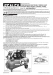
Installation and
Operating Instructions
SHALLOW WELL PRESSURE PUMPS & SYSTEMS
Models 95S, 125S, 165S
Read All Instructions First Before Commencing Installation of Your New Pump.
These instructions have been prepared to acquaint you with the correct method of installing and operating your Davey Pressure Pump or System. We urge you to study this publication carefully and follow its recommendations. If you have any installation difficulties, or need further advice, you should contact the Davey dealer from whom you purchased the system.
Should you be unable to obtain the required advice or resolve any problem through your local Davey dealer, please contact the Davey Customer
Service Centre.
Introduction
Davey Shallow Well Pressure Pumps and Pressure Systems have been designed to operate from surface water or shallow wells up to 7.5m (25
ft.) deep.
Note: For automatic operation as a Pressure System installation, the appropriate Davey Pressure Tank is required in addition to your Pressure
Pump.
Please pass these instructions on to the operator of this equipment.
Prior to using this pump you must ensure that:
• The pump is installed in a safe and dry environment
• The pump enclosure has adequate drainage in the event of leakage
• Any transport plugs are removed
• The pipe-work is correctly sealed and supported
• The pump is primed correctly
• The power supply is correctly connected
• All steps have been taken for safe operation
Appropriate details for all of these items are contained in the following Installation and Operating Instructions. Read these
in their entirety before switching on this pump. If you are uncertain as to any of these Installation and Operating Instructions
please contact your Davey dealer or the appropriate Davey office as listed on the back of this document.
Summary of Installation Procedure
For Automatic Operation as a Pressure System with Supercell Base Mounted Pressure Tank
(1)
Place tank next to pump as shown on the front of these instructions.
(2)
Connect Davey tank hose to bottom of discharge tee and tighten by hand (no thread sealant required).
(3)
Fit a gate valve to the 11/4” outlet.
(4)
Fit suction line complete with check valve or foot valve.
(5)
Fit discharge line.
(6)
Fit pressure gauge (supplied with pump) at top of pump.
For Automatic Operation as a Pressure System with Supercell Top Mounted Tank
(1)
Fit a Davey three way tee piece (P/No 48638) into the priming hole on top of the pump. Ensure adequate thread tape is
used.
(2)
Screw the Supercell pressure tank into the top of the three way tee using thread tape.
(3)
Perform steps (3) through to (5) above.
(4)
Fit the pressure gauge/priming plug to the horizontal outlet on the three way tee.
For Manual Operation
(1)
Disconnect pressure switch tube by undoing tubing nuts at outlet of pump and at pressure switch.
(2)
Tighten the cap on the bottom of the discharge tee.
(3)
Fit a gate valve to the 11/4” outlet.
(4)
Connect suction pipe complete with check valve or foot valve.
(5)
Connect discharge pipe.
(6)
Fit pressure gauge (supplied with pump) at top of pump.
Housing Your Pressure Pump System
For best performance position the Pressure Pump as close to the water source as practical.
As the pump is an electrical apparatus, it must be protected from the weather, at the same time adequate ventilation must
be provided for the motor. Do not enclose the pump in such a manner that a “hot box” condition is created. Ventilation should
be provided near the top of any enclosure to prevent a ‘build-up of condensation. Failure to protect your pump from weather as
above may cause damage not covered by Guarantee.
The pump should be mounted on a firm base high enough to prevent any surface water from coming into contact with the unit.
Positioning of the unit should allow the nameplate to be easily read, and adequate access for service purposes.
WARNING: Some insects, such as small ants, find electrical devices attractive for various reasons. If your pump
enclosure is susceptible to insect infestation you should implement a suitable pest control plan.
Water Quality
Your Davey pump is made from food safe materials, and tested using sanitised water. Davey has no control over your pump
once it leaves our warehouse.
For potable (drinking) water applications we recommend that you flush the pump with clean water prior to use.
Pipe Selection
Suction Piping
Polythene pipe is recommended for the pump suction as it provides flexibility, reduces the transmission of pump noises and
provides a convenient method of disconnecting the pump without unions or the need to cut into the piping.
Total suction head consists of the actual vertical height lift from the water level up to the pump inlet connection, PLUS the
frictional resistance of the suction piping and fittings. For best performance, position the pump as close to the water source as
practical.
To reduce pipe friction and maximise flow, we recommend the use of Suction Pipe Sizes for lengths indicated in the table below.
These pipe sizes are based on the Static Suction lift (vertical lift) being no more than 6m (20 ft.). For more detailed advice and
information regarding pipe sizes for longer suction situations or greater suction lifts please contact your Davey dealer or the
Davey Customer Service Centre.
-2-
Minimum Suction Pipe Diameter Recommended
Suction LengthUp to 10mUp to 30m
Model
MetricImperial
MetricImperial
95S
40mm
11/4”50mm
11/2”
11/2”
125S
40mm
11/4”50mm
2”
165S
50mm
11/2”63mm
Delivery Piping
Polythene piping which complies with the relevant Australian standard is recommended. Select the grade of pipe which has
a pressure rating suitable for your application. Galvanised or PVC piping may also be used provided the pressure rating is
adequate.
The pressure delivered by your Pressure Pump is reduced by the static delivery head (vertical height from pump to outlet
point) plus the friction loss caused by the piping itself. Static delivery head reduces the available pressure from the pump
by approximately 10kPa (1.4 psi) for every 1m (3.3 ft.) of head. The reduction in pressure due to pipe friction varies with the
length, diameter and type of piping used, as well as the flow rate through the pipe. The larger the diameter pipe, the smaller the
pressure drop by pipe friction.
The following pipe sizes are recommended for lengths up to 100m (330 ft.)
Minimum Discharge Pipe Diameter Recommended
Delivery Length
Up to 5m
Up to 30m
Up to 100m
Model
Metric ImperialMetric Imperial Metric Imperial
95S
32mm 1” 40mm11/4” 50mm11/2”
125S
32mm 1” 40mm11/4” 50mm11/2”
165S
40mm
11/4”50mm 11/2”63mm2”
For more accurate information please contact your local Davey Dealer or the Davey Customer Service Centre.
The electrical connections and checks must be made by a qualified electrician and comply with applicable
local standards.
Power Connection
In accordance with AS 3350.2.41 we are obliged to inform you that this pump is not to be used by children
or infirm persons and must not be used as a toy by children.
Single Phase
A power connection point should be provided by a qualified electrician within the pump housing.
Power connections and wiring must be carried out by an authorised electrician, in compliance with
applicable local standards.
Single phase Models are rated for 220/250 volts, 50 Hz operation, and may be connected to a standard 10 amp power outlet.
All single phase Models have automatic re-set thermal overload protection built in, i.e. should overload on motor cause thermal
to open circuit and switch motor off, it will automatically re-set and switch motor on when motor has cooled down sufficiently,
usually within a few minutes.
WARNING:
Automatic reset thermal overloads will allow the pump to restart without warning. ALWAYS disconnect the
pump motor from the electrical supply before maintenance or repairs.
Note: 1. Long extension leads should be avoided as they often have insufficient current carrying capacity to run electric
motors, hence they can cause substantial voltage drop and operating problems.
2. Minimum voltage at the electric motor must not fall below 216.
3. If the electrical fittings in your country make it necessary to remove the plug from the lead fixed to the motor care
should be taken to ensure that the earth conductor green/yellow in the lead is properly connected to a good earth.
This work must only be undertaken by an authorised electrician.
Three Phase
Model 165S only is also available as 3 phase model for 50Hz, nominal 415volt power supply. A recommended wiring diagram
can be found inside the capacitor cover (see figure one below). Three phase units must be wired in by an authorised electrician
in conjunction with a contactor which has “quicktrip” overloads set at nameplate current.
Davey recommend the use of overloads which also have the ability to detect “single phasing” or “dropped phase” conditions in
the power supply.
-3-
Three phase 165S Pressure Pump models have been designed to allow for
connection either side of the Capacitor Cover (marked “A” in figure one) on the
motor. (NOTE: Three phase motors do not have capacitors fitted in the Capacitor
Cover).
This is achieved by way of either of the two 19mm access holes (marked “B” in figure
one). The access holes are designed to accept most standard cable grommets. The
unused hole can be sealed by inserting the plug enclosed with the pump. To connect
a three phase Pressure Pump start by removing the Terminal Cover (“C”).
A short four core flex (“D”) is fitted from the
motor terminals (“E”). This lead is inserted through the blanking grommet (“F”).
Pressure switch or other control leads (“G”) can be fitted as well. Incoming power
(“H”) can be fitted through the preferred access hole, and terminated as shown in
Figure Three. A termination kit is available if required.
Insert the blanking grommet (“F”) into the capacitor cover (“A”). Fix the short lead (“D”)
into the path provided in the non-drive endshield and replace the terminal cover (“C”).
IMPORTANT NOTE: THREE PHASE MODELS ONLY
Before finalising wiring connections, check that motor rotates in direction of arrow (clockwise when shaft is
viewed from wiring connection end). To alter rotation, change any two power leads at motor terminals.
When the unit is connected and operating the phase balance should be checked. This should be within 5% variation. “Rolling”
the leads may help to improve a small unbalance, but major phase unbalance will usually be attributed to an input power
unbalance. This must be addressed before the pump is used.
Power connections and wiring must be carried out by an Authorised Electrician.
Note: Minimum three phase voltage supply at the motor must not fall below 374 volts, otherwise motor
damage may result which is not claimable under Guarantee.
INSTALLATION
Allow possible removal of the pump at some future date when attaching piping. (e.g. flexible hose and clips, pipe
union etc.).
The use of thread seal tape on all pump connections is recommended as some sealing compounds may affect plastic.
Suction Connections
Note: Air leaks in suction piping are THE BIGGEST cause of operating difficulties, and are hard to detect
because the problem is air leaking INTO the pipe. There may be no external sign of the leak.
Suction piping should be laid so there is a constant rise from the water source to the pump. Any high spots will cause air
pockets to form and reduce the efficiency of the system, as well as creating priming difficulties.
For installations which involve unavoidable high spots in the suction pipe, a “riser” for priming may overcome the problem.
(A)
Installations to Water Sources Below Pump
A foot valve must be used on the end of the suction pipe for all below ground installations. For optimum pump operation and
priming, ensure that the suction pipe is level, or rises evenly from the water source to the pump.
(B)
Installations to Water Sources Above Pump (e.g. Water Supply Tank)
To allow sediment to settle and not enter the pipe to the pump, the outlet from the supply tank should be 50mm (2”) above the
bottom. The outlet from the supply tank should be at least 38mm (11/2”) diameter, and fitted with a gate valve.
For Pressure System Installations, a check valve must be fitted to the supply tank outlet, alternatively, this check valve may be
installed at the pump rather than at the tank outlet.
-4-
Delivery Connections
A gate valve must be fitted at the outlet of all pumps prior to the connection of outlet piping.
(A)
Pumps to be Operated as Automatic Pressure Systems:
Base mounted tanks used
• Connect hose from Davey Supercell Pressure Tank to bottom of outlet tee on pump. Firm hand tight should be
sufficient. Ensure tank connection hose is not kinked.
• Fit gate valve to outlet tee of pump using thread seal tape.
• Connect delivery piping at gate valve.
TOP MOUNT TANKS
• Fit the Davey three way tee piece (P/No 48638) into the priming hole on top of the pump. Ensure adequate thread tape is used.
• Screw the tank into the top of the three way tee using thread tape.
• Fit gate valve to outlet tee of pump using thread tape.
• Connect delivery piping at gate valve.
NOTE: The use of small size pressure tanks may lead to a higher rate of pump cycling. Consult your Davey
dealer as to the suitability of the tank size to your application.
•
Fit the pressure gauge/priming plug to the horizontal outlet on the three way tee.
(B)
Pumps to be Operated Manually at Power Point:
• Disconnect pressure switch tube by undoing tube nuts at pump outlet and at pressure switch.
• Tighten the cap on the bottom of the the discharge tee.
• Fit gate valve to pump outlet (11/4” Female) using thread seal tape.
• Connect delivery piping at gate valve.
• Fit pressure gauge on top of pump. A non-return valve may need to be fitted in the delivery piping on some
installations to prevent water cascading back through the pump. Consult your Davey Dealer or the Davey Customer
Service Centre.
Pressure Tank Pre-Charge (Applicable to Pressure System Installation Only)
The Davey Supercell Pressure Tank requires the correct pre-charge of air for satisfactory operation. This pre-charge of air is
determined by the cut in pressure switch setting required for the particular system purchased. Check and adjust if necessary.
When a higher than standard pressure switch setting has been made, add air at the valve on top of the tank until the pressure is
15kPa below cut-in. Adjust this pre-charge BEFORE operating the pressure system.
Priming the Pump
(A)
`
When Installed on Water Sources Below Pump
Close gate valve at pump outlet. Remove the priming plug and fill pump body and suction pipe by pouring water into the
priming port on top of the pump. Air will be expelled, as the suction pipe is filled with water. When all air has ‘bubbled’ out,
replace the priming plug.
Do not run the pump without water.
(B)
When Installed on Water Sources Above Pump
Close gate valve at pump outlet. Remove the priming plug and fill the pump body by opening the gate valve on the
supply tank to allow water to flow into the pump. When the pump body is full and all the air bubbles have been expelled.
replace the priming plug.
Do not run the pump without discharge flow (closed head).
Operating the Pump
1.
2.
3.
4.
4a.
5.
5a.
6.
7.
Open nearest outlet tap.
Switch on power to pump.
Crack open gate valve at pump outlet to bleed trapped air from pump and pipework.
Allow pump to run until a change in sound of pump indicates that prime is established and pressure gauge reading rises
over 350 kPa.
If pressure fails to rise, switch off pump power and repeat priming.
Slowly open gate valve at pump outlet. A strong flow of water should be evident at an outlet tap indicating pump is
functioning.
If there is NO strong flow of water at the outlet tap, or the pressure gauge reading drops to 0, it may be necessary to reprime the pump. On long suction lines it may be necessary to re-prime several times to expel all the air from the suction
line to allow the pump to operate efficiently.
Open all taps in discharge pipe work.
Adjust gate valve at pump outlet so that pressure on gauge remains above operating pressure (standard 260kPa). Refer
Table for operating pressure of Models supplied with higher pressure jet kits.
-5-
To Check for Correct Operation as Automatic Pressure System
Close all outlet taps except one which should be turned on to allow small flow. Pump should build up pressure until it switches
off automatically at the cut-out pressure setting of the pressure switch (standard setting 380kPa, refer Table for others).
Pressure should then fall slowly as water flows from the one outlet tap until pump switches on automatically at cut- in setting of
pressure switch (standard setting 260kPa).
Pressure Switch
The pressure switch fitted to your Pressure Pump is required to function only if your pump is to operate automatically, in
conjunction with a Davey Supercell Pressure Tank.
Adjustment (if applicable)
The standard operating pressure and respective pressure switch setting for each Model is denoted by an asterisk (*) in the
Table below. Performances at pressures higher than standard are obtainable by fitting alternative shallow well jet kits, and for
these installations it is necessary to reset the pressure switch according to the Table below. Instructions for altering the pressure
switch setting are under the cover of the switch itself.
Power connections and wiring must be carried out by an Authorised Electrician.
Pressure Switch Setting when installed as Automatic Pressure System
Pressure SystemPressure Switch Settings
Model Jet
kPapsi
Kit
kPa
psiCut-InCut-OutCut-InCut-Out
95S
690*
260*
38*
260
380*
38
55*
691340 49 340510 49 74
125S
693*
260*
38*
260
380*
38
55*
694340 49 340510 49 74
695410 59 410590 59 85
165S
697*
260*
38*
260
380*
38
55*
698340 49 340510 49 74
699480 70 480660 70 96
*Standard configuration. NB: ‘psi’ figures are an approximation of the kPa figures.
*NOTE: For protection, the Davey pump motor is fitted with an automatic reset thermal overload, constant
tripping of this overload indicates a problem e.g. low voltage at pump, excessive temperature (above 50°C)
in pump enclosure.
Warning: Automatic reset thermal overloads will allow the pump to restart without warning. Always
disconnect the pump motor from the electrical supply before maintenance or repairs.
WARNING: When servicing or attending pump, always ensure power is switched off and lead unplugged.
Electrical connections should be serviced only by qualified persons.
Care should also be taken when servicing or disassembling pump to avoid possible injury from hot pressurised
water. Unplug pump, relieve pressure by opening a tap on the discharge side of the pump and allow any hot
water in the pump to cool before attempting to dismantle.
IMPORTANT: DO NOT USE petroleum based fluids or solvents (e.g. Oils, Kerosene, Turpentine, Thinners,
etc) on the plastic pump components or seal components.
WARNING: Do not use hydrocarbon based or hydrocarbon propelled sprays around the electrical
components of this pump.
-6-
Maintenance
Applicable for Models Operated as Pressure Systems Only
The only regular maintenance necessary is to check the air charge in the pressure tank. It is recommended that this be carried
out every 4 - 6 months as follows:
1.
To check air charge pressure, switch off the electric power to the pump. If the water level in your supply reservoir is
higher than the pump, also close the gate valve to prevent water entering the pump.
2.
Drain water from the pump by opening a convenient tap.
3.
When all the water (and hence pressure) has been released from the pump, pressure tank and piping, check air charge
pressure at air valve on top of tank using a tyre gauge. The pressure should be 15kPa (2 psi) below cut-in pressure
switch setting.
4.
Replenish air if necessary, and replace air valve cap securely.
Trouble Shooting
1.
Pump Not Delivering Water or Not Building Up Pressure:
May be caused by one or more of the following:–
(a)
Pump not properly primed;
(b)
Footvalve or checkvalve not installed or leaking;
(c)
Footvalve not installed below water level;
(d)
Suction lift too high;
(e)
Suction piping not correctly sealed or holed allowing air to enter pump suction:
(f)
Checkvalve installed in wrong direction;
(9)
Blocked jet or venturi in pump;
(h)
Insufficient water supply source.
2.Pump Not Starting:
May be caused by one or more of the following:–
(a)
Power failure;
(b)
Blown power fuse;
(c)
Motor overload tripped;
(d)
Motor windings faulty;
(e)
Pressure system not switching ON due to static delivery head causing higher pressure on the pump than the pressure
switch cut-in setting;
(f)
Low voltage power supply causing overload to operate;
(9)
Motor or pump seized.
3.
Pump (When Installed as Automatic Pressure System) Switching On and Off Frequently Or When No Taps
Turned On:
May be caused by one or more of the following:–
(a)
Footvalve or checkvalve not retaining pressure or water;
(b)
Water leaking from suction or delivery piping;
(c)
Leaking ball valve in toilet cistern, hot water system or stock troughs;
(d)
Pressure tank not retaining air pressure or air charge too high;
(e)
Motor thermal overload tripping.
4.
Pump (When installed as Automatic Pressure System) Not Switching Off Or Taking too Long to Switch Off:
May be caused by one or more of the following:–
(a)
Voltage supply too low;
(b)
Blocked jet or venturi in pump;
(c)
Leak in discharge pipe or fittings, taps etc.;
(d)
Worn or blocked pump components - impeller, pump body etc.;
(e)
Drop in water supply level.
-7-
Davey® Repair or Replacement Guarantee
In the unlikely event in Australia or New Zealand that this Davey product develops any malfunction
within two years of the date of original purchase due to faulty materials or manufacture, Davey will at
our option repair or replace it for you free of charge, subject to the conditions below.
Should you experience any difficulties with your Davey product, we suggest in the first instance that
you contact the Davey Dealer from which you purchased the Davey product. Alternatively you can
phone our Customer Service line on 1300 367 866 in Australia, or 0800 654 333 in New Zealand, or
send a written letter to Davey at the address listed below. On receipt of your claim, Davey will seek to
resolve your difficulties or, if the product is faulty or defective, advise you on how to have your Davey
product repaired, obtain a replacement or a refund.
Your Davey Two Year Guarantee naturally does not cover normal wear or tear, replacement of product
consumables (i.e. mechanical seals, bearings or capacitors), loss or damage resulting from misuse
or negligent handling, improper use for which the product was not designed or advertised, failure to
properly follow the provided installation and operating instructions, failure to carry out maintenance,
corrosive or abrasive water or other liquid, lightning or high voltage spikes, or unauthorized persons
attempting repairs. Where applicable, your Davey product must only be connected to the voltage
shown on the nameplate.
Your Davey Two Year Guarantee does not cover freight or any other costs incurred in making a claim.
Please retain your receipt as proof of purchase; you MUST provide evidence of the date of original
purchase when claiming under the Davey Two Year Guarantee.
Davey shall not be liable for any loss of profits or any consequential, indirect or special loss, damage or
injury of any kind whatsoever arising directly or indirectly from Davey products. This limitation does not
apply to any liability of Davey for failure to comply with a consumer guarantee applicable to your Davey
product under the Australian or New Zealand legislation and does not affect any rights or remedies that
may be available to you under the Australian or New Zealand Consumer Legislation.
In Australia, you are entitled to a replacement or refund for a major failure and for compensation for
any other reasonably foreseeable loss or damage. You are also entitled to have the goods repaired or
replaced if the goods fail to be of acceptable quality and the failure does not amount to a major failure.
Should your Davey product require repair or service after the guarantee period; contact your nearest
Davey Dealer or phone the Davey Customer Service Centre on the number listed below.
For a complete list of Davey Dealers visit our website (davey.com.au) or call:
AUSTRALIA
NEW ZEALAND
Customer Service Centre
6 Lakeview Drive,
Scoresby, Australia 3179
Ph:
1300 367 866
Fax:
1300 369 119
Website:davey.com.au
Customer Service Centre
7 Rockridge Avenue,
Penrose, Auckland 1061
Ph:
0800 654 333
Fax:
09 527 7654
Website:daveynz.co.nz
Davey Water Products Pty Ltd
Member of the GUD Group
ABN 18 066 327 517
® Davey is a registered trade mark of Davey Water Products Pty Ltd.
© Davey Water Products Pty Ltd 2011.
P/N 48163-9 supersedes P/N 48163-8
* Installation and operating instructions are included with the product when purchased new.
They may also be found on our website.