1
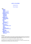
Installation and Operating Instructions for Differential Pressure Sensor Water Tank Level Medium Range Telemetry System. _______________________________________________________________________________________________________ This system uses 100mW transceiver modules with frequency-hopping technology designed to minimize interference. Range is typically 0.5 km urban and up to 5 km rural, with a theoretical 24km range. Tank Level Pressure Sensor and RF Transmitter Installation. • Unscrew the lid on the tank sensor unit and install 4 AA batteries (See figure 1.) • Lower the pressure sensor and cable through an appropriate hole or opening above the water level in the tank and ensure that the sensor is sitting on the bottom of the tank. Excess cable can be pushed into the tank. Secure the case to the tank with 2 screws • The transmitter should be mounted as high as possible. • If necessary it can be observed that the green LED on the circuit board containing the wireless transmitter inside the unit will light up and flicker when each reading is being transmitted. Normally one reading is sent approximately every 10 seconds for the first 3 hrs then one reading every 30 seconds thereafter. RF Receiver and Aquagauge Display Unit Installation. • Mount the receiver antenna as high as possible and as close to line-of-sight to the transmitter as practicable. • The receiver and display unit have a single power supply. Plug in the 120-240V AC to 9V DC power adapter to the display unit and press the power on/off button. • Press the “DISPLAY” key to switch between sensor readings. • The display will initially show ”0” and if no RF signal is being received from any sensor and then “Nil" will be displayed after about 4 minutes if no signal is received. • The display will retain a reading for about 4 minutes if no new data is received. The unit must therefore be periodically switched on and off when testing reception range. Data Logging and Charting Software Option. If the system has been purchased with the optional serial data collection package (for WINDOWS 95 or latter WINDOWS operating system) then the AQUACHART software supplied on CD will need to be installed. Insert the CD and run the setup program and follow the instructions. Once installed, connect the supplied serial cable to the socket on the AQUAGAUGE display unit and an available serial port on the PC. Check that the chosen serial port is not allocated to other software running on the PC. Start the AQUACHART software and select appropriate data collection parameters as follows: Serial Port: select the COM port to which the serial cable is connected. Make sure that no other software is using the com port that you connect to. Data Storage Buffer Size: default size is 51200. This value will determine the number of data points available for display in the main text box. If the data buffer size is exceeded it will automatically be saved and appended to a file named Aquachart_overflow_data.txt Time Interval Between Readings: Choose an appropriate interval for data collection Initial x-axis Span: Determines the initial time span for the data plots. The START button commences data collection Electrosense Technologies 2011 1 The STOP button stops data collection The CLEAR button erases all data The PRINT button prints the graphs The SAVE button will save the data displayed in the text box in a text file of choice Drag handles are provided on the charts for data rescaling and a cursor can be used to determine x,y values at any position on both charts. TRANSMITTER/SENSOR RECEIVER/DISPLAY OPTIONAL DATA LOGGING AND CHARTING SOFTWARE Figure 1. Electrosense Technologies 2011 2 SYSTEM INSTALLATION DIAGRAM Sensor-processor and RF transmitter units RF receiver unit Water tank Display unit Data cable Power supply PC running charting software Pressure sensor Electrosense Technologies 2011 3