1
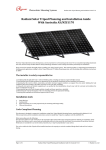
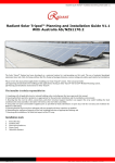
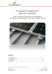
GroundLock Installation Manual
Version 1 – updated August 2011
Australian
Made
www.sunlock.com.au
Introduction
Thank you for choosing the GroundLock solar photovoltaic
(PV) module ground-mounted framing system, part of the
SunLock family of solar framing products. Offering a high
level of adjustability for terrain and the desired inclination,
GroundLock is suitable for a wide variety of commercial
and remote installations.
GroundLock and SunLock are backed by a 10-year
warranty and are compliant with the Australian / New
Zealand Standard on Wind Actions (AS/NZS1170.2.2011).
Each GroundLock frame can support up to twelve PV
modules with dimensions 1665 x 991 mm (such as the
REC 235), providing a peak power of 2.8 kW. Multiple
GroundLock frames can be installed on one site to provide
increased power.
WARNING
Indicates a hazardous situation which, if not
avoided, can result in death or serious injury
or moderate injury.
CAUTION
Indicates a hazardous condition which,
if not avoided,can result in minor
or moderate injury.
Installation manual – Version 1 (updated August 2011)
2
safety
Wind loads
The GroundLock frame has been assessed and rated
to be in compliance with AS/NZS1170.2.2011 on Wind
Actions, for the following regions:
20˚
20˚
• Wind region A (most of Australia)
• Terrain Category 2, 3, 4
(sites with few obstructions, or built up areas)
• Topographic factor MT = 1.0
(on level or near level ground)
Note: AS/NZS1170.2.2011 provides guidance on
determining the wind pressures applicable to your
GroundLock install site, taking into account local terrain
and topography. Sufficient guidance is given in this
document, but you may wish to procure a copy of these
standards if your company installs Australia wide.
25˚
25˚
27˚
30˚
30˚
Region A
Region B
Region C
Any attempt by an unqualified person to install this product
could result in death or serious injury.
Region D
Wind regions based on
AS1170.2 - 2011
Footings
Wind region A is wind speeds up to 41ms (W41)
Wind region B is wind speeds up to 54ms (W54)
Wind region C is wind speeds up to 58ms (W58)
The footings for GroundLock have been designed by a
registered structural engineer, and are appropriate for
natural ground, not topsoil, fill, or disturbed ground.
MT 1
Check that the soil at the install location is appropriate for
this footing design. If it is not appropriate, you will need to
get the footing checked by a registered structural engineer.
Handling
The materials used in the GroundLock frame can have
sharp corners or edges. Wear personal protective
equipment such as safety glasses, hearing protection and
gloves during cutting and handling.
Installation manual – Version 1 (updated August 2011)
Terrain Category 2 (TC2)
Terrain Category 3 (TC3)
3
Tools Required
for Installation
-bar Allen Key or 6 mm hexagonal driver bit. If using a
T
6 mm driver bit, make sure the cordless power tool used
for driving has a hand-tight clutch setting and a fine (soft)
impact drive to prevent damage to the fragile glass panels
and threads on the SunLock framing.
Gloves for handling framing (aluminium and steel can
develop sharp corners).
If required, an angle grinder with a metal cutting blade can
be used to trim the posts to length. Gloves, hearing
protection, a face protection mask, and a suitably rated
breathing protection mask must be used by all people in
proximity of cutting.
Drill and driver for driving fixings.
Drill bit for drilling bolt holes.
Ring spanner for tightening fixing bolts.
Installation manual – Version 1 (updated August 2011)
4
Typical Installation
GroundLock can compensate for up to 300 mm slope
at the installation site by adjusting the length of the posts.
Extensive bracing and triangulation produces a robust
and stiff structure.
The images shown in this installation manual are for
a frame with an inclination angle of 25 degrees.
The assembly process is the same for models with
other angles of inclination. The maximum angle of
inclination is 40 degrees.
Installation manual – Version 1 (updated August 2011)
5
Installation
The GroundLock frame consists of a lower steel frame
and an upper aluminium frame. The steel frame is held
in concrete footings.
The aluminium frame includes the SunLock rails. The PV
modules are attached to the SunLock rails using standard
SunLock mid-clamps and end-clamps.
Steel frame
The steel frame is constructed from cold formed galvanized
c-sections (Lysaght 152 x 64 x 19.5 x 2.4 mm lipped CFS).
1. Mark out the location of the footings:
•The posts are spaced at 1950 mm centres (East-West)
•The back row is placed at 2070 mm back from the front
row (North–South)
2. Dig or bore the holes to the required depth as defined:
•P1–300 mm diameter & 900 mm deep
•P2–300 mm diameter & 1200 mm deep
Note that each post is supplied with an extra 300 mm –
either the posts should be shortened to suit the terrain, or
the footings should be made deeper.
3. Measure and cut each post to length, accounting for
sloping terrain; the horizontal beams are 600 mm
(minimum) above ground level
4. Drill and insert the anchor bolt into the base of each
post. This bolt ensures that the post is anchored
adequately in the concrete footing.
5. Concrete the posts in place with concrete of minimum
strength 25 MPa, ensuring that the base of the post is a
minimum of 100 mm from the bottom of the hole.
6. Drill and bolt the horizontal beams to the posts:
•Splice the sections to form two 6 m length beams,
using the supplied splicing (joining) kit. Use the prepunched holes in the splicing kit as a template to drill
the required holes in the beams.
•Bolt the horizontal beams to the posts using three M8
stainless bolts and nyloc nuts at every joint
Installation manual – Version 1 (updated August 2011)
6
Aluminium frame
The aluminium frame is mounted on top of the steel frame,
and includes the SunLock rails. The aluminium frame is
constructed from:
• SunLock rails
• 50 x 50 x 6 mm aluminium angle brackets
• 40 x 40 x 6 mm aluminium angle
• 40 x 40 x 3 mm aluminium angle, and
• 40 x 3 mm aluminium flat.
Installation manual – Version 1 (updated August 2011)
7
Aluminium frame
1 Place mounting feet at prescribed locations on the
C–section beams, drill holes and connect together
using the supplied stainless steel hardware.
Installation manual – Version 1 (updated August 2011)
2 At the front (north side) of the frame, connect the
triangular mounting plates and associated fasteners to
the mounting feet.
3 The vertical legs are made from 40 x 40 x 6 mm
aluminium angle.The base of each leg is attached to
the mounting feet using an M8 stainless steel bolt. The
top of each leg is attached to the SunLock rail using a
triangular mounting plate.
8
Aluminium frame
4 Brace the centre of each SunLock rail to the base of
the leg using 40 x 40 x 3 mm aluminium angle. The top
of each brace is attached to the SunLock rail using a
triangular mounting plate.
The base of each brace is attached to the leg using an
M8 stainless steel bolt. One brace must be installed per
SunLock rail.
Installation manual – Version 1 (updated August 2011)
5 Brace the rear (south side) of the frame using 40 x 3 mm
aluminium flat and M8 stainless steel bolts with nyloc
nuts. Ensure the rear legs are mounted vertically prior to
bracing the unit correctly.
To brace the legs, use the pre–drilled holes in the
40 x 3 mm aluminium flat straps as a template for the
required holes in the rear legs. Attach with supplied M8
stainless steel bolts and nyloc nuts.
9
PV Modules
Images provided are suited for roof mounted applications.
Installation references can also be used for ground
mounted solutions.
1. Installing End Clamps
2. Install Mid Clamps
3. Installing Mid Clamps
Insert the keylock of the end clamp into the rail channel.
Using a 6 mm hex driver/Allen key, secure the first solar
panel to the rail. Position the frame of the solar panel 50mm
from the end of the rail.
Insert the keylock of the mid clamp into the rail channe
and position the clamp against the first panel frame.
Hand tighten the screw 2–3 turns to loosely hold the clamp
in position. If Earthlock washers are used, they should be
placed between the SunLock rail and the frame of the panel.
Slide second panel firmly into place against the
mid clamps and fasten bolts.
4. Check Alignment of the Array
5. Continue Installing Mid Clamps
6. Install End Clamps
After fixing the first 2 panels, check that the array is
straight. If there appears to be a deviation from square
(e.g. if the ridge cap shows the row to be falling or rising
slightly), readjust the panels until they appear square with
the roof. Alternatively, measure the distance from the rail
to the edge of the panel.
Continue to clamp the neighbouring panels in the array
to the rails.
Finish the array row by securing the remaining two end
clamps. You should have a minimum of 50 mm clearance
between the edge of the last panel and the end of the rail.
Tighten all bolts to secure the panels.
Installation manual – Version 1 (updated August 2011)
10
Earthing
Cabling and DC isolator
Maintenance and Cleaning
If a transformerless inverter is used, the frames of the
PV modules must be earthed to the SunLock rails using
EarthLock washers. Furthermore, each SunLock rail must
be connected to earth using EarthLock bonding terminals.
Securely fix all cables to the SunLock rails using the
supplied UV resistant cable ties or UV resistant cable clips.
Cable runs along the C-section beams should be within UV
resistant conduit.
Mount the DC isolator to one post.
6106-T6 aluminium is largely maintenance free.
Only in highly polluted or marine conditions is rinsing
with clean water required, during scheduled panel cleaning.
Earthlock Bonding Terminal
Fasten the EarthLock bonding terminal directly to a
SunLock rail by placing the insert key in the rail and
tightening the cap screw.
Installation manual – Version 1 (updated August 2011)
11
Warranty Conditions
Energy Matters Pty Ltd (trading as Energy Matters and Apollo
Energy) (Energy Matters) warrants that its GroundLock and
SunLock Solar Panel Mounting System (Frame) is free from
defects in materials and workmanship for a period of 10 years
from the date on which the Frame is purchased from Energy
Matters (Warranty Period), on the terms set out in this warranty.
In the event that the Frame does not conform to this warranty
during the Warranty Period, Energy Matters will, at its option,
either repair or replace the Frame or pay the cost of having the
Frame repaired or replaced.
To the extent permitted by law, Energy Matters’s total liability
under this warranty will in no circumstances exceed the repair
or replacement of the Frame or payment of the cost of having
the Frame repaired or replaced. In the event of replacement of
the Frame, any remaining part of the Warranty Period will be
transferred to the replacement Frame.
This warranty will not apply to any defect or damage to the
Frame arising directly or indirectly from:
1. shipment or storage of the Frame;
2. improper installation, maintenance, repair or use of the
Frame;
3. normal wear and tear;
4. misuse, neglect, abuse, accidental damage or modification
to the Frame;
5. failure to observe the instructions set out in the System
Manual; or
6. power failure, power surges, lightning, fire, explosion, flood,
extreme weather conditions, environmental disasters or
other causes outside Energy Matters’ control, as determined
by Energy Matters in its sole discretion.
Installation manual – Version 1 (updated August 2011)
This warranty does not cover, and under no circumstances
will Energy Matters be liable for, any costs associated with
the removal, shipping, handling or re-installation of the
Frame or the costs of sending personnel to any site to
repair or replace the Frame.This warranty is only provided
to the original purchaser of the Frame from Energy Matters
(Purchaser) or, where the Purchaser is an installer or builder
who on-supplies the Frame to another party, to that other
party (End-User).
Any provision contained in this warranty which is
prohibited or unenforceable in any jurisdiction will be
deemed to be ineffective to the extent of such prohibition
or unenforceability and will not invalidate the remaining
provisions nor affect the validity or enforceability of that
provision in any other jurisdiction.
This warranty will be governed and construed in accordance
with the laws of Victoria, Australia and the parties irrevocably
submit to the exclusive jurisdiction of the courts of Victoria.
This warranty is not transferable. Where an End-User wants
make a claim under this warranty, the End-User must in the
first instance contact the installer or builder from whom the
Frame was purchased.
All warranty claims must be made in writing and addressed to
the Customer Service Officer, Energy Matters, PO Box 5265,
South Melbourne, Victoria, 3205; and accompanied by proof of
purchase of the Frame in a form acceptable to Energy Matters.
This warranty will not apply to any claims received by Energy
Matters after the expiration of the Warranty Period. Energy
Matters makes no warranties, express or implied, other than
the warranties made herein, and specifically disclaims all
other warranties, representations and conditions to the extent
permitted by law.
To the extent permitted by law, in no circumstances will
Energy Matters be liable for direct, indirect, special or
consequential damages arising from a defective Frame or
for any damage or injury to persons or property. Energy
Matters’ aggregate liability, if any, in damages or otherwise,
will not exceed the invoice value of the Frame at the time of
purchase from Energy Matters.
12
REFERENCES
CERTIFICATE
AS/NZS1170.2.2011, structural design actions,
Part 2: Wind actions
AS/NZS1170.2.2011 certificate of structural adequacy
from registered structural engineer, Partridge Partners:
CONTACT DETAILS
For further information contact Apollo Energy
on 1300 855 484 (local call from anywhere in Australia)
or at [email protected]
Installation manual – Version 1 (updated August 2011)
13