1
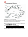
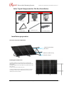
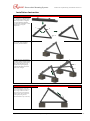
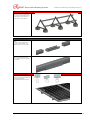
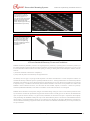
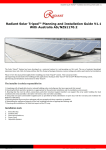
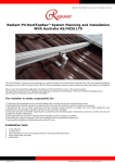
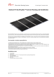
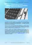
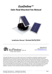
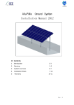
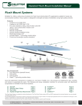
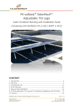
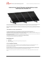
Photovoltaic Mounting Systems Radiant Solar Tripod Planning and Installation Guide V1.0 Radiant Solar Tripod Planning and Installation Guide With Australia AS/NZS1170 The Solar Tripod System has been developed as a universal system for roof-mounting on flat roofs. The use of patented (pending) aluminium base rails, Click-In Clamp and Base Rail Pre-Clamp technology eliminates custom cutting and enables particularly fast installation. Please review this manual thoroughly before installing your Solar Tripod system. This manual provides (1) supporting documentation for building permit applications relating to Solar Tripod Universal PV Module Mounting system, and (2) planning and installation instructions for RMS™. The installer is solely responsible for: 1. Complying with all applicable local or national building codes, including any that may superseded this manual; 2. Ensuring that Rack and other products are appropriate for the particular installation and the installation environment; 3. Ensuring that the roof, its rafters, connections, and other structural support members can support the array under building live load conditions (this total assembly is hereafter referred to as the roof rafter assembly); 4. Using only rack parts and installer-supplied parts as specified by Rack (substitution of parts may void the warranty and invalidate the letter of certification on page 2); 5. Ensuring that lag screws have adequate pullout strength and shear capacities as installed; 6. Maintaining the waterproof integrity of the roof, including selection of appropriate flashing; 7. Ensuring safe installation of all electrical aspects of the PV array. Installation tools 1. 2. 3. 4. 6mm Allen key; Cordless drill; Open-end spanner set 13 mm (required only for mounting with hanger bolts); Plain end screwdriver Code-Compliant Planning This document is designed to support for installations using Solar Tripod Module Mounting System, manufactured by Radiant Co. Ltd. Follow steps below and the installation instructions section to install Solar Tripod in compliance with the AS/NZS1170. Before proceeding, note the following: This document addresses only wind loads on the assumption that wind produces the maximum load factor affecting an installation. Verify that other local factors, such as snow loads and earth quake effects, do not exceed the wind loads. Give precedence to any factor that does. Wind loads are considered to act on the entire projected area, or may be perpendicular to any surface. The roof on which the Solar Tripod will be installed must have the capacity to resist the combined Design Dead Load and Live Load per footing. Page 1 of 6 Radiant Solar Tripod Planning and Installation Guide for Australia V1.0 Radiant Co. Ltd Photovoltaic Mounting Systems Radiant Solar Tripod Planning and Installation Guide V1.0 1. Determine the wind region of your installation site Region Definition: Wind regions are pre defined for all of Australia by Australian Standard 1170. The Wind Region has nothing to do with surrounding topography or buildings. Most of Australia is designated Region A which indicates a Regional Ultimate Basic Wind Velocity of 45msec. Some areas are designated Region B (57msec). Local authorities will advise if this applies in your area. Region C areas (66msec) are generally refered to as Cyclonic and are generally limited to northern coastal areas. Most Region C zones end 100km inland. Region D (80msec) Australia's worst Cyclonic Region between Carnarvon and Pardoo in Western Australia. 2. Determine the height of the of your installation site This document provides sufficient information for Solar Tripod system installation height less than 20 meters. If your installation site is more than 20 meters in height, please contact Radiant to obtain engineering data to support your installation. 3. Determine the Maximum Rail Support Spacing Please use the following table to determine the base rail support spacing for flat roof installations. Installation Height Region A (mm) Region B (mm) Region C (mm) 5 Meters 2400 2250 2020 10 Meters 2230 2140 1910 15 Meters 2120 2050 1840 20 Meters 2030 1980 1780 Region D (mm) 1730 1660 1590 1510 The figures above are based on attaching 200W PV modules (length of 1700mm, weight of 30KG) to Solar Tripod system. These figures should be sufficient for installing smaller PV modules. Please consult Radiant for installing PV modules greater than length of 1700mm and weight of 30KG. Page 2 of 6 Radiant Solar Tripod Planning and Installation Guide for Australia V1.0 Radiant Co. Ltd Photovoltaic Mounting Systems Radiant Solar Tripod Planning and Installation Guide V1.0 Solar Tripod Components for Flat Roof Installation Overview of system components Base Rail 60 PV-Solar Tripod Modules middle Clamp Wind Cross Set Modules End Clamp Base Rail40/60 Splice Installation preparation Overview of system components Modules End Clamp Base Rail Modules middle Clamp PV-Solar Tripod Planning the module area 1. Number of modules in the vertical direction x module height (please check also the installation manual of the manufacturer of the solar module) 2. Number of modules in horizontal direction x (module width + 23.5 mm) + 60 mm 3. Distance between the modules: 23.5 mm * Caution: Installations that are exposed to the wind or are located on the edge or corners of the roof may make it necessary to leave smaller spaces between modules. Page 3 of 6 Radiant Solar Tripod Planning and Installation Guide for Australia V1.0 Radiant Co. Ltd Photovoltaic Mounting Systems Radiant Solar Tripod Planning and Installation Guide V1.0 Installation Instruction Solar Tripod Installation 1. As shown in drawing, rotate the component a and component b as the direction in photo , then adjust component b ’ s length as your need and fasten it tightly , then fasten the component a and component b using the component c . a b C 2. Fasten the Solar Tripod with the precast concrete tightly , then array the others like it. 3. Wind Cross Set installation (If your Solar Tripod needed). Unfold the wind cross set as the drawing shows, and eaten the cross set with the solar tripod tightly by using hex bolt M8*45 in order to improve the strength. a b Base Rail Installation 4. Installation the rails on the Solar Tripod, If your set of rails consists with different length, we always begin with the shortest piece. Put the base rail slide into klicktop of the Solar Tripod, and fasten tightly using the nut. (Recommended torque is 18 Nm). Page 4 of 6 Radiant Solar Tripod Planning and Installation Guide for Australia V1.0 Radiant Co. Ltd Photovoltaic Mounting Systems Radiant Solar Tripod Planning and Installation Guide V1.0 Base Rail Installation 5. Position the first frame rails for each row, and fasten tightly with the nut. (Recommended torque is 18 Nm). Please pay attention to Figure when you installation. Base Rail Splice Installation 6. Install the base rails with rail splice. To connect with multiple rails together, slide the rails to the middle of splice from two sides. 7. Fasten the both connections between splice and rails with M12*12 Allen bolt by using Allen keys tightly. PV Module Installation 8. Put the module end clamp insert to the base rail, and then fasten the end clamp and modules with Allen bolt tightly. (recommended torque is 8 Nm). Page 5 of 6 Radiant Solar Tripod Planning and Installation Guide for Australia V1.0 Radiant Co. Ltd Photovoltaic Mounting Systems Radiant Solar Tripod Planning and Installation Guide V1.0 Base Rail Splice Installation 9. Put module middle clamp inset the rails from above, place it firmly against the module and fasten loosely (approx. 2 - 3 turns). Now inset the next module against the previously installed module and tighten the intermodule clamp using the Allen key (recommended torque is 8 Nm). PV Module Dismounting 10. Disassembly of end clamp kit. Loosing inside hexagonal bolt on the clamp kit using 6mm Allen key, then hold out against the bottom part of clamp kit using plain end screwdriver. Put down the handle of plain end screwdriver 15 Years Standard Warranty Terms and Conditions RADIANT International (“RADIANT”) warrants to the original purchaser (“Purchaser”) of product(s) that it manufactures (“Product”) at the original installation site that the Product shall be free from defects in material and workmanship for a period of ten (15) years, except for the anodized finish which shall be free from visible peeling, or cracking or chalking under normal atmospheric conditions, from the earlier of: 1). the date the installation of the Product is completed, or; 2). 30 days after the purchase of the Product by the original Purchaser. The Warranty does not apply to any foreign residue deposited on the finish. All installations in corrosive atmospheric conditions are excluded. The Warranty is VOID if the practices specified by AAMA 609 & 610-02 – “Cleaning and Maintenance for Architecturally Finished Aluminium” (www.aamanet.org) are not followed by Purchaser. This Warranty does not cover damage to the Product that occurs during its shipment, storage, or installation. This Warranty shall be VOID if installation of the Product is not performed in accordance with RADIANT’s written installation instructions, or if the Product has been modified, repaired, or reworked in a manner not previously authorized by RADIANT IN WRITING, or if the Product is installed in an environment for which it was not designed. RADIANT shall not be liable for consequential, contingent or incidental damages arising out of the use of the Product by Purchaser under any circumstances. If within the specified Warranty periods the Product shall be reasonably proven to be defective, then RADIANT shall repair or replace the defective Product, or any part thereof, in RADIANT’s sole discretion. Such repair or replacement shall completely satisfy and discharge all of RADIANT’s liability with respect to this Limited Warranty. Under no circumstances shall RADIANT be liable for special, indirect or consequential damages arising out of or related to use by Purchaser of the Product. Manufacturers of related items, such as PV modules and flashings, may provide written warranties of their own. RADIANT’s Limited Warranty covers only its Product, and not any related items. Page 6 of 6 Radiant Solar Tripod Planning and Installation Guide for Australia V1.0 Radiant Co. Ltd