1
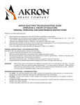
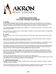
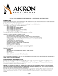
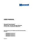
STYLE 3491 Severe Duty Electric Mining Water Cannon
INSTALLATION, AND OPERATING INSTRUCTIONS
Australian Only
The following is intended to provide the basic instructions for installation, operating and maintenance of the
Severe Duty Monitor.
Tools Required
o Utility knife o Medium flat screwdriver
o Medium Phillips screwdriver o Small flat screwdriver
o Small Phillips screwdriver o 1/2 inch hex head wrench
o Electrician’s pliers (multipurpose, stripping and crimping)
PRODUCT RATINGS
Maximum motor current draw:
12 volt versions
24 volt versions
15.0 amps each for elevation and rotation motors
3.0 amps for nozzle pattern motor
7.5 amps each for elevation and rotation motors
1.5 amps for nozzle pattern motor
Normal operating current (depending on operating conditions - pressure, flow, etc.):
12 volt versions 3 - 10 amps each for elevation and rotation motors
0.7 amps for nozzle pattern motor
24 volt versions
2 - 5 amps each for elevation and rotation motors
0.4 amps for nozzle pattern motor
Minimum Voltage: (Truck engine must be operating for proper voltage requirement.)
All 12 volt motors: 11.5 volts while operating
All 24 volt motors: 23 volts while operating
Mass: 57 lbs. (26 kg)
Maximum Flow: 750 GPM (2840 lpm)
Maximum Pressure: 200 PSI (14 bar)
Noise Emission: 91 Db @1m with maximum flow
PRODUCT WARNINGS
WARNING: The maximum flow of the Severe Duty is 750 GPM. The center of the waterway outlet is 8.25 inches from the bottom of the inlet. Ensure these values and an appropriate safety factor is used to determine a proper support structure.
WARNING:
Aim the Severe Duty in a safe direction before pumping water through it.
WARNING:
WARNING:
WARNING:
WARNING:
Although the logic box includes a water resistant coating it is important to keep water out of the logic box. Prolonged exposure to water will cause damage. When the cover of the logic box is removed check that the O-Ring under the cover is intact and free of dirt and debris.
The Severe Duty uses current limiting for both the monitor and nozzle stops. Use only appropriate
Akron Brass nozzles.
Make the connection of the vehicle and auxiliary battery the final step.
If any tags or bands are worn or damaged and cannot be easily read, they should be replaced.
120956
WARNING:
WARNING:
WARNING:
WARNING:
WARNING:
Disconnect power and disable flow before maintenance.
Keep all personnel out from the front of the outlet of the monitor when the water source is attached. Dangerous flow velocities can cause serious injury.
The Severe Duty monitor contains moving parts. Keep hand, finger and objects away from pinch points.
Not designed for explosive environments.
Exceeding the maximum pressure and flow of the monitor or nozzle may cause damage.
WARRANTY AND DISCLAIMER
We warrant Akron Brass products for a period of one (1) year after purchase against defects in materials or
workmanship. Akron Brass will repair or replace product which fails to satisfy this warranty. Repair or replacement shall
be at the discretion of Akron Brass. Products must be promptly returned to Akron Brass for warranty service. We will
not be responsible for: wear and tear, any improper installation, use, maintenance or storage: negligence of the owner or
user; repair or modification after delivery; failure to follow our instructions or recommendations; or anything else beyond
our control. WE MAKE NO WARRANTIES, EXPRESS OR IMPLIED, OTHER THAN THOSE INCLUDED IN THIS
WARRANTY STATEMENT, AND WE DISCLAIM ANY IMPLIED WARRANTY OF MERCHANTABILITY OR FITNESS FOR
ANY PARTICULAR PURPOSE. Further, we will not be responsible for any consequential, incidental or indirect damages
(including, but not limited to, any loss of profits) from any cause whatsoever. No person has authority to change this
warranty.
GENERAL INSTRUCTIONS
•
Review the instructions, wiring diagram, component layout and rotational stops diagram before installing this unit. This unit operates on 12 volt DC or 24 volt DC depending on the unit chosen. All electrical
current flows through the wires. The monitor does not act as a ground.
•
For use with water or standard fire fighting foams only. After use with foam, flush with fresh water.
•
Drain the Severe Duty monitor and nozzle after use to prevent “freeze damage” in cold weather.
•
Ensure that the thread in the nozzle swivel matches the thread on the Severe Duty outlet. Do not
overtighten the nozzle onto the Severe Duty Monitor.
•
The Severe Duty monitor, nozzle, logic box, control boxes, optional battery, and field adjustable rotation stops are made for optimal performance, Do not alter in any manner.
•
Do not install shutoffs on the outlet of the Severe Duty.
•
Mount the logic box, control boxes out of range from the monitor travel.
INSTALLATION INSTRUCTIONS
A. ELECTRICAL INSTALLATION
STEP 1Plug the joystick cable connector into the logic box connector marked “JOYSTICK”
STEP 2Plug the monitor harness connector to the logic box connector marked “MONITOR”
STEP 3Connect vehicle power to the logic box connector marked “POWER”
NOTE: Adequately sized wire must be used based on the current requirements of the monitor. See Chart below
(Figure 1)
Based on Vehicle Power of 13.8V (12V system) and 27.6V (24V system) and max currents of 30A (12V system) or 15A
(24V system).
Wire Size (AWG)
Wire Lengths
(Ft.)
12V
24V
10
14
16
20
12
14
30
10
12
40
8
10
50
8
10
FIGURE 1
STEP 4Connect optional water valve harness to logic box connector marked “VALVE” if supplied.
B. MECHANICAL MONITOR ATTACHMENT
The Monitor is to be mounted on the waterway with a 21⁄2” NPT thread. The monitor may have an optional 3” or 4”
flange with a short nipple.
THE ROTATIONAL AND ELEVATION STOPS SET THE BOUNDARIES FOR THE AREA IN WHICH THE MONITOR IS
ALLOWED TO TRAVEL. The monitor is shipped with rotation stops at 90˚ right, and at 90˚ left, 320° can be achieved by
switching the factory set stop and the plug in the desired stop location. Both the stops and the plugs have a 1/2 inch hex head. Refer to Page 7 to determine which stop location is needed for the desired rotation. The elevation stop sets the
upper limit of the elevation. The monitor is shipped with elevation stops at 90° above horizontal and 65˚ below horizontal.
An optional stop at 20° below horizontal can be achieved by switching plugs and stops to the desired locations as indicated in figure 5.
OPERATING INSTRUCTIONS
A. JOYSTICK WITH TRIGGER FOR VALVE
To change the nozzle pattern toward the straight stream or fog press the corresponding button on top of the Joystick. To change the horizontal position right or left move the Joystick towards the appropriate direction. To change the vertical position up or down move the Joystick forward for down and backwards for up. To open and close the valve, press the trigger to open the valve and release the trigger to close the valve. The valve
can be maintained open by pressing the valve switch towards open. Note: When valve is maintained open, the trigger will not operate the valve.
B. LEARN MODE (OPTIONAL)
The stow position can learn a new position by pressing and holding the Stow button. When the monitor reaches the default stowed position (Straight Out), continue to hold the Stow button while operating the up or down
button until the desired position. Let go of just the up or down button and that will be the new elevated stow
position. While continuing to hold the stow button operating the left or right button until the desired position. Release both buttons. This will be the new stowed position. If the stowed button is released at any time during the process, stop and restart the sequence.
MAINTENANCE INSTRUCTIONS
Your Severe Duty monitor and nozzle should be inspected prior to and after each use, to ensure it is in good
operating condition. The monitor joints were greased and sealed at assembly, there is no greasing to be done while in use.
SITUATIONS THAT MAY CAUSE IRRERPAIRABLE DAMAGE
• Operating above maximum rated pressure and flow.
• Not draining, and allowing water to freeze inside.
• Prolonged exposure to temperatures above 130°F (54°C), or below -25°F (-32°C).
• Having the nozzle hit a fixed object during operating or transportation.
Also there are many “tell tale” signs that indicate repair is in order, such as:
• Controls that are either inoperable or difficult to operate.
• Excessive wear.
• Poor discharge performance.
• Water leaks.
If any of the above situations are encountered, the Severe Duty should be taken out of service, repaired, and tested by a qualified technician before placing it back in service.
To replace either the horizontal or vertical rotational motors, see the technical service manual (#120960) for detailed
instructions on motor and joint replacement.
Figure 2
right side
14-1/2
90° Left stop
Plug
2-1/2" NPT FeMALe
(dO NOT PAiNT)
13-9/16
Elevation Movement:
+90° -65° (Standard) Can Be Changed
By Customer To +90° -20°
Front
2-1/2" NH THreAd
dO NOT PAiNT THis AreA
320° stop
right
90° right stop
Plug
Left
14-3/16
Back
NOTE: For 320° rotation remove both 90° Stop pins and replace with plugs. Remove plug
at 320° location and install stop pin.
(ROTATED 90°)
14-1/2
12-29/32
102
10-9/32 11-7/8
9/32 THRU, TYP. 4
9-1/8
9-11/32
22-7/64
VALVE
TRIGGER
OPEN
STREAM
11-3/4
READ OPERATING INSTRUCTIONS BEFORE USE
FOG
Figure 3
PROG
RUN
LOGIC BOX
DWG. D-44147
P/N 34911000
DIP
SWITCHES
VALVE
DEUTSCH
IPD-USA
DTM04-12P
JOYSTICK
DWG. D-44150
P/N 34911001
AB P/N & REV
MFG S/N OR
BATCH CODE
JOYSTICK
ROTATION
EXTENSION CABLE
DWG. D-44149
P/N 707526 (20 FT. )
P/N 707527 (33 FT. )
P/N 707528 (40 FT. )
ELEVATION
PATTERN
ROTATION
WIRING HARNESS
DWG. D-44148
P/N 121479
ELEVATION
Figure 4
GN/BK
BLACK
WHITE
WHITE
GREEN
BLACK
BLACK
BLACK
RED
WHITE
2
WHITE
LOCATION 2 - BLACK
LOCATION 1 - WHITE
1
2
3
4
+
+
SYSTEM VDC
POWER IN
TB2
(WHITE) VALVE MOTOR OPEN
(ORG) ROT. MOTOR LEFT
(BLK) VALVE MOTOR CLOSED
(BLU) ROT. MOTOR RIGHT
ELEV OSC ON
(BLK) ELEV. MOTOR UP
(RED/BLK) ROT. LIMIT SWITCH
(RED) ELEV. MOTOR DOWN
(GRN/BLK) ELEV. LIMIT SWITCH
(GRN) PATTERN MOTOR FOG
(WHT/BLK) +SYSTEM VDC OUT TO LIMIT SWITCHES
(WHT) PATTERN MOTOR STREAM
(ORG) MOMENTARY INPUT SWITCH VALVE
(PUR) MAINTAINED INPUT SWITCH VALVE
AUTO-LEVEL +12/24 VOLT
AUTO-LEVEL GROUND
14
13
12
11
10
9
8
7
6
5
4
3
2
1
TB3
21
19
18
17
16
15
24
25
26
27
28
23 20
22
21 22
20 23
19 24
18 25
17 26
16 27
15 28
STYLE 3463 FIREFOX MONITOR
1
2
3
4
5
6
7
8
9
10
11
12
13
14
TB1
GREEN
BLUE
BLUE
BLACK
ORANGE
WHITE
RD/BK
BLACK
ORANGE/BLACK - NOT USED, CUT OFF
AUTO-LEVEL DOWN
FOR 40% SPEED, USE BOTH 60% & 80% INPUTS
INPUT SWITCH FOG (BRN)
INPUT SWITCH STREAM (YEL)
ROT OSC ON (BLK)
INPUT SWITCH STOW (WHT)
ROT SPEED 60%
INPUT SWITCH RIGHT (BLK)
ROT SPEED 80%
INPUT SWITCH LEFT (RED)
ELEV SPEED 60%
INPUT SWITCH DOWN (BLU)
ELEV SPEED 80%
INPUT SWITCH UP (GRN)
FROM LOW
SPEED SWITCH
1
2
3
4
Return to Stream During Stow
5
Wide Auto-oscillation Range
6
Use the Learned Positions
7
Enable LEARN Mode 8
+SYSTEM VDC OUT TO SPEED SWITCH
+SYSTEM VDC OUT TO SWITCHES (WHT)
OSC LED (RED)
VALVE LED (GRY)
OSC OFF (BRN)
AUTO-LEVEL ON/OFF
AUTO-LEVEL UP
FACTORY USE ONLY
RUN MODE
WHITE
BROWN
UP
UP
DOWN
DOWN
DOWN
DOWN
UP
UP
GRY
YELLOW
DIP FUNCTIONS
UP = ON
ORANGE
DOWN
Water ON Only if Deployed
RIGHT/LEFT Cancels Auto-osc
Enable Slow Speeds
FROM JOYSTICK
CONTROL BOX
(WITH STOW
OPTION ONLY)
FROM
CONTROL BOX/
JOYSTICK
RIGHT
WHITE
WHITE
LEFT
PURPLE- TO PANEL VALVE SWITCH
GRAY- TO VALVE LED
UP
BLACK
20 AWG
LOCATION 1 - WHITE
FROM
MONITOR
14 AWG, + SYSTEM VDC VEHICLE BATTERY (+)
2 COND.
WHITE
RED
18 AWG,
4 COND.
LOCATION 2 - BLACK
14 AWG,
2 COND.
(BLK) VEHICLE GROUND (-)
16 AWG,
10 COND.
FROM
VALVE MOTOR
MASTER
Factory Settings
LABEL REV 11
DWG D41670
WHITE
2
WIRING HARNESS
WHT
BLK
RED
WHT
WHITE
BROWN
YELLOW
ORANGE
JOYSTICK
WHITE
TO PANEL SWITCHES
BLACK +V BULK
GRAY -FOG
WHITE - SS
BROWN - TRIGGER
OPEN
VALVE LED
+V bulk
PURPLE
GRAY
WHITE
Figure 5
PUR
SLAVE
WH/BK
Figure 6
sTOP FOr
90fl ABOve
HOriZONTAL
(sTANdArd)
8
OPTiONAL sTOP
LOCATiON FOr
-20fl BELOW
HOriZONTAL
8
1
-65fl BELOW
HOriZONTAL
(sTANdArd)
OPTiONAL sTOP
LOCATiON FOr 320°
rOTATiON
(Uses ONLY 1 sTOP)
sTOP FOr
90° TO THe LeFT
(sTANdArd)
sTOP FOr
90° TO THe riGHT
(sTANdArd)
PHONE: 330.264.5678 or 800.228.1161 I FAX: 330.264.2944 or 800.531.7335 I www.akronbrass.com
revised: 6/08
WARRANTY AND DISCLAIMER: We warrant Akron Brass products for a period of five (5) years after purchase against defects in materials or workmanship. Akron Brass will repair or replace
product which fails to satisfy this warranty. Repair or replacement shall be at the discretion of Akron Brass. Products must be promptly returned to Akron Brass for warranty service.
ISO 9001 REGISTERED COMPANY
We will not be responsible for: wear and tear; any improper installation, use, maintenance or storage; negligence of the owner or user; repair or modification after delivery; damage; failure to
follow our instructions or recommendations; or anything else beyond our control. WE MAKE NO WARRANTIES, EXPRESS OR IMPLIED, OTHER THAN THOSE INCLUDED IN THIS WARRANTY
STATEMENT, AND WE DISCLAIM ANY IMPLIED WARRANTY OF MERCHANTABILITY OR FITNESS FOR ANY PARTICULAR PURPOSE. Further, we will not be responsible for any consequential,
incidental or indirect damages (including, but not limited to, any loss of profits) from any cause whatsoever. No person has authority to change this warranty.
© Premier Farnell Corporation. 2000 All rights reserved. No portion of this can be
reproduced without the express written consent of Premier Farnell Corporation.