1
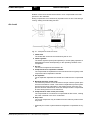
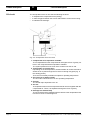
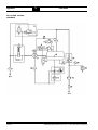
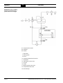
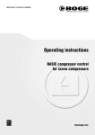
Product description
2.2
Function description
Rotation of the rotors causes the air taken in to be compressed to the final
pressure in the chambers.
During compression oil is continuously injected into the air end. This having a
cooling, sealing and lubricating function.
Air circuit
Fig. 2.1: Components of the air circuit
1 Intake filter
The intake filter cleans the air suctioned by the air end.
2 Intake regulator
The intake regulator opens (load operation) or closes (idling operation or
standstill) the suction line depending on the operating condition of the
compressor.
3 Air end
The air end compresses the sucked in air.
4 Compressed air/oil separation chamber
The compressed air separates from the oil under the force of gravity in the
compressed air/oil separation chamber.
5 Oil separator
The oil separator separates the residual oil contained in the compressed
air.
6 Minimum pressure check valve
The minimum pressure check valve does not open until the system pressure has increased to 3.5 bar. This causes a rapid build-up of the system
pressure and ensures lubrication in the starting phase. Once the compressor has been switched off, the check valve prevents the compressed
air from flowing back out of the mains line.
7* Compressed air after-cooler (air cooled)
The compressed air is cooled in the compressed air after-cooler, causing
the water contained in the air to condensate.
8 Stop valve
The screw compressor may be isolated from the mains by means of the
stop valve.
* Optionally for receiver systems without refrigeration compressed air dryers
BOGE Operating instructions for C 10 L...C 20 L series screw compressors
Page 15