1
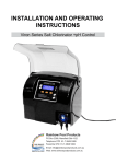
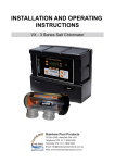
CONTROLLERS Installation & Operating Instructions Please pass on to the owner of this equipment… 1 CONTROLLERS Index: Your Davey ClevaLink Controller……………………….. Packing Lists…………………………………………….... Product Overview…………………………………………. Features……………………………………………………. Technical Data…………………………………………….. Dimensions……………………………………………….... Installing the MCU….......................……………………... Programming the MCU................................................... Setting the Clock............................................................. Setting up the Remote.................................................... Master Control Unit Menu Structure................................ Adding an LCU to the MCU............................................ Setting Up a Group......................................................... Removing an LCU from the MCU................................... Setting the Timers.......................................................... Renaming an Outlet........................................................ Editing “Favourites”......................................................... Resetting the Factory Settings....................................... LCU Installation.............................................................. Operating the LCU......................................................... PG. 2 PG. 3 PG. 4 PG. 5 PG. 6 PG. 6 PG. 6 PG. 7 PG. 7 PG. 8 PG. 9 PG. 10 PG. 10 PG. 11 PG. 11 PG. 12 PG. 12 PG. 13 PG. 14 PG. 14 Rainbow Pool Products PO Box 2388, Mansfield Qld 4122 Telephone STD 61-7-3849 5385 Facsimile STD 61-7-3849 5384 Email: [email protected] Web: www.rainbowpoolproducts.com.au 2 Your Davey ClevaLink Controller: Congratulations on the purchase of your Davey ClevaLink Controller. You have made an excellent choice for the convenient and automated control of your swimming pool, spa and other appliances around the home, farm or workplace. The Davey ClevaLink Controller system includes a Master Control Unit (MCU) and a Link Control Unit (LCU) and a Clevalink Remote Control (CLR) which can be operated together or individually to suit your personal needs. If your needs change, you can simply add another LCU device. Packing Lists: Model CLMCUR CLLCUR Description CleverLink Master Control Unit (MCU) with Remote Control CleverLink Link Control Unit (LCU) with Remote Control CLLCU CleverLink Link Control Unit (LCU) CLR CleverLink Remote Control Contains Master Controller 8 Channel Remote Installation & Operating Instructions Wall mounting kit 3 x Remote labels Link Controller 8 Channel Remote Installation & Operating Instructions Wall mounting kit 3 x Remote labels Link Controller Installation & Operating Instructions Wall mounting kit 8 Channel Radio Frequency Remote Installation & Operating Instructions 3 x Remote labels 3 Product Overview: Master Control Centre (MCU) 1 . 11 0. 2 . 10 0. 3 . 4 . 1. 2. 3. 4. 5. 6. 5 . 9 . 6 . Default display Day of the week Outlet Name/ Number Favourites 1 to 4 Exit Back Up Arrow 7 . 8 . 7. Down Arrow 8. Forward Advance 9. Select /Confirm 10. Status of Outlet 11. Current Time The MCU is a sophisticated controller, which includes 16 inbuilt timers, 8 appliance group functions, and macro functions for the ultimate in easy, convenient control. The MCU provides automated wireless control over multiple ClevaLink units so you can easily control many different appliances. It is easy to set up and operate, just set and forget. It includes a clear LCD display, simple touchpad controls and 2 x 10 Amp outlets in a robust, weatherproof, wall-mountable unit. It also comes with an 8 channel remote control to control individual appliances or grouped appliances at the press of one button. 4 CleverLink Remote Control (CLR): 3 . 1 . 2 . 1. 8 x Function LED 3. Red / Green signal LED 2. 8 x Pushbuttons DAVEY ClevaLink Features: MCU LCU Remote Control Clear backlit LCD display Simple touchpad controls 16 Timers Group up to 8 Independent outlets Up to 8 Macros with 4 programmable functions 8 Channel Remote transceiver Favourite Functions menu 4 x Favourite Hot Keys for simple control from touchpad Long memory backup from super-capacitor Dual outlet switch over ride 2 x 10A outlets can be controlled by remote and / or Master Control Unit (MCU) Available with 8 channel remote transmitter Dual outlet switch over ride 8 Hot buttons to control wirelessly connected appliances, groups or macro functions Function ON/OFF LED’s Signal strength LED Simple to use Weather and water resistant (Not water proof) 5 Technical Data: Model Power (V) Power Outlets Outlet rating (A) Power Lead length (m) Electrical Approval IP MCU / LCU 220-240 2 10A Total 1.9 NSW23093 53 Dimensions: (mm) Height Width Depth Mounting Holes (Horiz) MCU LCU 208 124 119 88 99 99 Mounting Holes (Vert) 188 104 Mounting Holes Diam 5 Installing the Master Control Unit (MCU): 1. When installing your MCU it is easier to program the network prior to mounting. Simply plug in to any power outlet to activate the unit and begin programming. Refer to the section titled “Programming the MCU”. 2. Mount the MCU in a location that is greater than 3.5 meters from the pool zone and less than 1.5 meters from a power supply socket. Make sure the unit is within range of other units before mounting. 3. Plug the appliances to be controlled, into the outlets in the base of the MCU. WARNING: The total current of the MCU must not exceed 10 Amp. The unit must be installed in the upright position. 4. Plug the mains input lead into the power outlet 240V supply. 5. Switch on the power outlet and the 2 override switches on the MCU unit (mechanical rocker switch above the outlets). 6 Programming the MCU: When installing a network of ClevaLink Master Controller and Link Control Units, it is easier to program the network prior to installation. Hot Keys At any time pressing Hotkeys 1 to 4 on the MCU touchpad will activate Favourites 1 to 4. All other buttons are used to navigate the menus. Below is a list of the SMART LINKING CONTROL Master Controller menus. Setting the Clock: Press Selected Main Menu Display Equipment Set Timers X6 Settings Menu Set Clock Clock Set Up remote Settings Set Clock Factory Reset Sunday 01:47:00 Change clock Monday 09:12:00 Adjust the time Monday 09:12:00 Store Changes Monday 09:12:00 7 Setting up the Remote (MCU): WARNING: Do not drop or submerge the remote control in water. It is only resistant to wet hands. Set up the remote to control an appliance or group Press Selected Main Menu Display Equipment Set Timers Setup Remote Menu OR Select Outlet, Group or Macro to be controlled Transmit I.D. Press and hold selected remote button Signal LED will flash Green When I.D. has been sent Function LED will flash Red Then Green. Store Changes Edit Favourites Set Up Remote Outlet 1 Outlet 2 Transmitting Outlet 1 Transmitting Outlet 1 Record the function of the remote button on the label supplied NOTE: Once you have set up your remote control, you can record the function of each remote button on the labels supplied with the unit. 8 Master Control Unit (MCU) Menu Structure: Main Menu Equipment Set Timers Equipment Access Units Add Equipment Rename Outlet Remove Equipment Select Unit Type 2 x 10A Outlets 15A Outlets Timers Timer 1 : Set Timers Timer x: on/off Act: Function Timer 16 Setup Macros Macros Macro 1 : Macro 8 2 x 10A Outlets Unit 1 : Unit 16 15A Outlets Unit 1 : Unit 16 Turn: on/off Select Unit Type 2 Time: hr:min Day: 2 Channel Units 2 x 10A Outlets Unit 1 : Unit 16 15A Units 15A Outlets Unit 1 : Unit 16 Group Groups Group 1 : Group 8 Macro Macros Macro 1 : Macro 8 Set Macros Act: Function Turn: on/off Wait: hr:min Act: Function Turn: on/off Wait: hr:min Act: Function Turn: on/off Wait: hr:min Act: Function Turn: on/off Setup Groups Groups Group 1 : Group 8 Setup Groups Function 1 : Function 8 Edit Favourites Favourites Favourite 1 : Favourite 16 Select Unit Type 2 Setup Remote Select Function Output 1 Output 2 Group 1 : Group 8 Macro 1 : Macro 8 Settings Settings Set Clock Factory Reset Firmware Version Factory Reset Select Unit Type Set Clock Day hr:min Press to enter main menu from default display Press to navigate through menu structure Press to save a setting Returns to last screen 9 Setting Up a Group: Use this Function to wirelessly connect and activate multiple outputs with one action. Select Press / Use Main Menu Press Menu ( ) Button Setup Groups Press Arrow Up/Down to find “Setup Groups”. Select with Enter button. A list of 8 Groups will appear. Select Group Press Arrow Up/Down to find new group. Select with Enter button. Note: For new groups 8 x “Free Space” spots will appear. Free Space Press Enter ( ) . Type of outlet (2x10A or Press Arrow Up/Down button to select outlet type. Select 15A). with Enter button. Select Outlet / named Press Arrow Up/Down button to select an outlet / appliance appliance for the group. Press Enter. Arrow Up/Down button to select another outlet / appliance for the group. Press Enter( ) . Repeat for up to 8 appliances. Exit to Default display Press Exit button x 3 / Wait 30 secs for screen to return to screen default display Adding an LCU to the Master Control Unit: To wirelessly connect one or multiple LCU devices to the MCU First read Installing an LCU on Page 14 Select Main Menu Equipment Menu Add Equipment Search for local LCU Press / Use Press Menu ( ) Button Press Menu ( ) Button Press Arrow Up/Down to find “Add Equipment”. Select with Enter button Press Menu button to activate “Searching”. ((((( Searching )))))) Exit to Default display screen Press and hold a button on the top of the LCU to transmit its ID. When the LCU (outlet) is found the display will read “Unit Added”. Press the OK or Press Menu/Enter ( ) Button Press Exit button x 2 / Wait 30 secs for screen to return to default display. To rename the new unit, see “Renaming an Outlet” 10 Setting the Timers: Select Main Menu Set Timers The timer which you want to use “ACT” Type of outlet. 10A or 15A The appliance to be controlled “On Time” “Day” “Off Time” “Day” Exit to Default display screen Press / Use Menu ( ) Button Arrow Up/Down to locate. Select with Enter ( Arrow Up/Down to locate. Select with Enter ( ) button. ) button. Arrow down to locate. Select with Enter ( ) button Arrow Up/Down to locate. Select with Enter ( ) button. Arrow Up/Down to locate. Select with Enter ( ) button. Display will return to timer set up display. Arrow down to locate “On Time”. Select with Enter ( ) button. Enter ( ) again to select Hours or Minutes. Use UP/DOWN cycle through numbers. Press OK when complete. To change press Enter( ). Use UP/DOWN arrows to select “Weekends”, “Every Day” or a day of the week. Press OK Arrow down to locate “Off Time”. Select with Enter ( ) button. Enter ( ) again to select Hours or Minutes. Use UP/DOWN cycle through numbers. Press OK when complete. As above Exit button x 4 / Wait 30 secs for screen to return to default display Removing an LCU from the MCU: Select Press / Use Main Menu Press Menu ( Equipment Menu Remove Outlet Press Menu ( ) Button Press Arrow Up/Down to find “Remove outlet”. Select with Enter button The outlet type Press Arrow Up/Down button to select outlet type (2x10A or 15A). Select with Enter button. The appliance Press Arrow Up/Down button to select the appliance (or New Unit) to be removed. Select with Enter button. Exit to Default display screen Press Exit button x 4 / Wait 30 secs for screen to return to default display ) Button 11 Renaming an Outlet: Select Main Menu Equipment Menu Rename Outlet Type of outlet to be renamed (2x10A or 15A). Appliance to be renamed New Name Exit to Default display screen Press / Use Press Menu ( ) Button Press Menu ( ) Button Press Arrow Up/Down to find “Rename outlet”. Select with Enter button Press Arrow Up/Down button to select outlet to be renamed. Select with Enter button. A list of appliances / outlets will appear. Press Arrow Up/Down to find name to change. Select with Enter button. The name will flash. Press Arrow Up/Down to find new name from list. OK to select. If name not available press Enter to write a new name. Use Arrow Up/Down buttons to select letters or numbers to complete name. Press Enter to move through characters. Press OK to complete. Press Exit button x 5 / Wait 30 secs for screen to return to default display Editing “Favourites”: Once LCU’s (Outlets) have been added to the Master Control Centre, the outlets, Groups & Macros can be added to the Favourites list and the order rearranged. The 4 “Favourites” buttons on the MCU touchpad activate the first 4 in the favourites list. If you create a group or a macro you can edit the favourites to include them on the Hot Keys. Select Main Menu Edit Favourites Desired Favourites position Type of outlet. 10A or 15A? Desired appliance from Access Equipment Menu Exit to Default display screen Press / Use Press Menu ( ) Button Press Arrow Up/Down to “Edit Favourites” with down button. Select with Enter button Press Arrow Up/Down button to select position of favourite. Select with Enter button. Press Arrow Up/Down button to select outlet. Select with Enter button. Press Arrow Up/Down through the appliance list & select with Enter ( ) button. If you cannot find desired appliance in the list, create own using Enter button, followed by Up/Down arrows to select alpha/numeric forms. Press Exit button x 3 / Wait 30 secs for screen to return to default display 12 Resetting the Factory Settings: The Settings menu provides access to the Factory Reset sub-menu. When Factory Reset is selected by pressing the ENTER or OK buttons a confirmation screen is displayed. If the OK button is then pressed the unit will delete all programmed data and return to the original state. Select Main Menu Settings Factory Reset Press / Use Press Menu ( ) Button Press Arrow Up/Down to “Settings”. Select with Menu button Press Arrow Up/Down to “Settings”. Select with Menu button _________________________________________________________ Link Control Unit (LCU) 1 . 2 . 1. Outlet 1 indicator LED 3. Outlet 2 indicator LED 4 . 3 . 2. Outlet 1 override / program LED 4. Outlet 2 override / program LED _________________________________________________________ The LCU is a 2 x 10 Amp weatherproof and wall mountable outlet that can be remote controlled and wirelessly linked to the MCU and other LCU’s to control your pool and yard appliances. 13 Installing an LCU: 1. When installing your LCU it is easier to program the network prior to mounting. Simply plug in to any power outlet to activate the unit and begin programming. Refer to the section titled “Operating the LCU”. 2. Mount the LCU in a location that is greater than 3.5 meters from the pool zone and less than 1.5 meters from a power supply socket. 3. Plug the appliances to be controlled, into the outlets in the base of the LCU. WARNING: The total current of the LCU must not exceed 10 Amp 4. Plugs the mains input lead into the power outlet 240V supply. 5. Switch on the power outlet and the 2 override switches on the LCU unit (mechanical rocker switch above the outlets). Operating the LCU: Press Selected Press and Hold outlet power button, Red LED Will start to flash, keep holding and go to next step. Display Press and hold selected remote button, Signal LED will flash Green when I.D. has been sent, Function LED will flash when I.D. has been received. Release buttons. Record the function of the remote button on the label supplied 14 DAVEY WATER PRODUCTS GUARANTEE FOR AUSTRALIA & NEW ZEALAND This Davey product is guaranteed to be free of material or manufacturing defects for one year………. TERMS AND CONDITIONS 1. This guarantee applies to all states and territories of Australia and New Zealand only and is subject to the provisions of the Trade Practices Act (Aust.), the Goods and Consumer Protection Legislation of the various Australian states and the Consumers Guarantee Act 1993 (NZ) as applicable. 2. The guarantee period commences on the date of original purchase of the equipment. Evidence of this date of original purchase must be provided when claiming repairs under guarantee. It is recommended you retain all receipts in a safe place. 3. This guarantee covers parts and workshop labour only. Goods should be forwarded, with proof of date of original purchase, to an Authorised Davey Service Centre freight paid. Any travel and removal/reinstalling charges for goods repaired infield will be to the owners account. Guarantee may be denied on goods not readily accessible for service personnel or mounted on exterior walls above single storey level. 4. The guarantee for commercial applications such as hotels, motels, caravan parks, health clubs, public pools etc. is for 12 months (1 year) only, subject to equipment sizing in accordance with Davey’s recommendations. 5. This guarantee is subject to due compliance by the original purchaser with all directions and conditions set out in the Installation and Operating Instructions. Failure to comply with these instructions, damage or breakdown caused by fair wear and tear, negligence, misuse, incorrect installation, chemical or additives in the water, inadequate protection against freezing, rain or other adverse weather conditions, corrosive or abrasive water, lightning or high voltage spikes or through unauthorised persons attempting repairs are not covered under guarantee. The product must only be connected to the voltage shown on the nameplate. 6. Without limiting the original purchaser’s entitlements under the Trade Practices Act (Aust.), the Goods & Consumer Protection Legislation of the various Australian states, or the Consumers Guarantee Act 1993 (NZ), Davey shall not be liable for any loss of profits or any consequential, indirect or special loss, damage or injury of any kind whatsoever arising directly or indirectly from the product or any defect. 7. Where the Trade Practices Act (Aust.), the Goods and Consumer Protection Legislation of the various Australian states and the Consumers Guarantee Act 1993 (NZ) does not apply. Davey shall not be liable for any loss of profits or any consequential, indirect or special loss, damage or injury of any kind whatsoever suffered by the purchaser arising directly or indirectly from the product or any defect and the purchaser shall indemnify Davey against any claim by any other person whatsoever in respect of any such loss, damage or injury. 8. Nothing in this guarantee is intended to have the effect of contracting out of the provisions of the Trade Practices Act (Aust.), the Goods and Consumer Protection Legislation of the various Australian states and Consumers Guarantee Act 1993 (NZ) except to the extent permitted by the various Acts and this guarantee is to be modified to the extent necessary to give effect to that intention. Davey may be collecting personal information from you in order to provide you with a service. Davey Water Products Pty Ltd promises only to use this information in accordance with the Provisions of the 9. 15