1
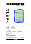
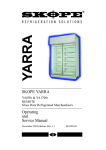
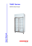
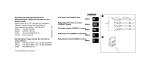
Vertical Display and Storage
TMEF650
MAN9515 Rev. 2.1 Mar. 2004 edition
Operating and Service Manual
SKOPE Single Door Economy Freezer
CONTACT ADDRESSES
Designed and Manufactured by
New Zealand
SKOPE INDUSTRIES LIMITED
PO Box 1091, Christchurch
New Zealand
Freephone: 0800 947 5673
Fax: (03) 983 3896
E-mail: [email protected]
Website: www.skope.co.nz
Australia
SKOPE AUSTRALIA PTY LTD
A.C.N. 000 384 270
PO Box 7543, Baulkham Hills B.C.
NSW 2153, Australia
Freephone: 1800 121 535
Fax: 1800 121 533
E-mail: [email protected]
Website: www.skope.com.au
TMEF650
SKOPE Single Door Economy Freezer
i
TMEF650
Operating and Service Manual
MAN9515
Rev. 2.1 Mar. 2004 edition.
Published by SKOPE Industries
Limited, Christchurch, New Zealand.
Copyright © 2002
by SKOPE Industries Limited.
All rights reserved.
SKOPE and CYCLONE are
registered trademarks of SKOPE
Industries Limited.
SKOPE Industries Limited reserve the
right to alter specifications without
notice.
ii
TMEF650
SKOPE Single Door Economy Freezer
TABLE OF CONTENTS
1
SPECIFICATIONS
1.1
1.2
Features . . . . . . . . . . . . . . . . . . . . . . . . . . . . . . . . . . . . . . . . 7
Cabinet and Refrigeration Unit . . . . . . . . . . . . . . . . . . . . . . . 8
2
INSTALLATION
2.1
2.2
2.3
Introduction . . . . . . . . . . . . . . . . . . . . . . . . . . . . . . . . . . . . . . 9
Positioning of Machine . . . . . . . . . . . . . . . . . . . . . . . . . . . . . 9
Ventilation . . . . . . . . . . . . . . . . . . . . . . . . . . . . . . . . . . . . . . 10
3
OPERATION
3.1
3.2
3.3
3.4
Safety Information . . . . . . . . . . . . . . . . . . . . . . . . . . . . . . . . 11
Operation of Machine . . . . . . . . . . . . . . . . . . . . . . . . . . . . . 12
Loading . . . . . . . . . . . . . . . . . . . . . . . . . . . . . . . . . . . . . . . . 14
Cleaning . . . . . . . . . . . . . . . . . . . . . . . . . . . . . . . . . . . . . . . 14
4
ELECTRONIC CONTROLLER
4.1
4.2
4.3
4.4
4.5
4.6
Controller Display . . . . . . . . . . . . . . . . . . . . . . . . . . . . . . . . 15
Controller Components . . . . . . . . . . . . . . . . . . . . . . . . . . . . 16
Operation of Controller . . . . . . . . . . . . . . . . . . . . . . . . . . . . 17
Parameters . . . . . . . . . . . . . . . . . . . . . . . . . . . . . . . . . . . . . 19
Alarms and Signals . . . . . . . . . . . . . . . . . . . . . . . . . . . . . . . 22
Replacement . . . . . . . . . . . . . . . . . . . . . . . . . . . . . . . . . . . 25
5
SERVICE INSTRUCTIONS
5.1
5.2
5.3
5.4
5.5
5.6
5.7
System Service Notes . . . . . . . . . . . . . . . . . . . . . . . . . . . . 26
Pre-Service Check Information . . . . . . . . . . . . . . . . . . . . . . 28
Interior Side Light . . . . . . . . . . . . . . . . . . . . . . . . . . . . . . . . 29
Doors . . . . . . . . . . . . . . . . . . . . . . . . . . . . . . . . . . . . . . . . . . 30
Refrigeration Unit. . . . . . . . . . . . . . . . . . . . . . . . . . . . . . . . . 32
Pressure Temperature Chart. . . . . . . . . . . . . . . . . . . . . . . . 35
Trouble Shooting Chart . . . . . . . . . . . . . . . . . . . . . . . . . . . . 36
TMEF650
SKOPE Single Door Economy Freezer
iii
TABLE OF CONTENTS
6
WIRING DIAGRAM
6.1
Model TMEF650. . . . . . . . . . . . . . . . . . . . . . . . . . . . . . . . . 40
7
SPARES
7.1
7.2
7.3
Cabinet Assembly . . . . . . . . . . . . . . . . . . . . . . . . . . . . . . . 42
Door . . . . . . . . . . . . . . . . . . . . . . . . . . . . . . . . . . . . . . . . . . 43
Refrigeration Unit . . . . . . . . . . . . . . . . . . . . . . . . . . . . . . . . 44
8
NOTES
8.1
Notes . . . . . . . . . . . . . . . . . . . . . . . . . . . . . . . . . . . . . . . . . 45
iv
TMEF650
SKOPE Single Door Economy Freezer
1
SPECIFICATIONS
1.1 Features
Ventilated plain facia panel
Triple glazed heated swing door
Interior side light
Front mounted condenser
Adjustable wire
shelves
CAREL controller
Figure 1: Glass Door Model
Solid swing door with
recessed handle
Swivel castors
Figure 2: Solid Door Model
TMEF650
Top Mounted Economy Freezer
7
1
SPECIFICATIONS
1.2 Cabinet and Refrigeration Unit
CABINET CONSTRUCTION
Exterior/Interior:
Insulation:
White powdercoat on galvanised steel.
50mm thick, polyurethane foam.
Cyclo-iso Pentane blowing agent: C5H10/C5H12
DIMENSIONS
Height:
Width:
Depth:
Floor area:
Internal volume:
2195mm
740mm
700mm
0.52m2
610 litres
REFRIGERATION
Top mounted SKOPE Cyclone® refrigeration unit:
Nominal capacity:
690 Watts
Compressor:
Danfoss SC18CL
Refrigerant:
R404A
Charge:
550 grams
ELECTRICAL
230-240 Volts a.c. 50 Hz, single phase power supply.
Run Amps:
7.2 Amps
LIGHTING
Interior side light:
58 Watt (5ft) fluorescent tube (glass door model)
DOORS
Self-closing, aluminium framed, triple glazed, heated, toughened safety
glass, or self-closing, foam filled, galvanised steel solid door.
SHELVES
White powdercoated, adjustable height, steel wire shelves.
8
TMEF650
SKOPE Single Door Economy Freezer
2 INSTALLATION
2.1 Introduction
The new TMEF650 freezer is designed to better integrate the installation of the SKOPE chiller and freezer products, while also providing a more cost effective alternative to the existing range of SKOPE
CLF/SKF freezers. New features of the TMEF650 freezer include:
• Front mounted condenser
• 5 foot interior side light
• The ability to be pushed hard back against the wall
• Quieter running
• 10 Amp plug
2.2 Positioning of Machine
The mains flex exits out the top of the refrigeration unit. The flex
should be retrieved before the machine is positioned, when walls
and partitions may make access difficult.
For efficient operation of machine, it is essential that adequate ventilation be provided above the refrigeration unit. When positioning the
machine, a gap must be left between the top of the refrigeration unit
and ceiling, of at least 200mm. Maximum recommended operating
ambient temperature for the machine is 25°C.
When siting the machine, avoid direct sunlight, warm draughts etc.,
and adequate allowance should be made for door opening. The door
has an internal torsion bar which is pretensioned at the factory. The
machine must be positioned on a level surface for the door to shut
and seal correctly, and to prevent the condensate tray from overflowing.
Remove all packaging material from the shelves. Fit shelf support
brackets at the desired heights and relocate shelves.
TMEF650
Top Mounted Economy Freezer
9
2 INSTALLATION
2.3 Ventilation
Even though the machine can be positioned hard against a back
wall, adequate ventilation of the refrigeration unit is essential. Air
surrounding condenser must not exceed 30°C. Never store cardboard cartons or other items on top of the refrigeration unit.
Warning:
Adequate ventilation of the refrigeration unit is essential.
Ceiling
200 mm
Airflow
Wall
Front of cabinet
Figure 3: Ventilation
10
TMEF650
SKOPE Single Door Economy Freezer
3 OPERATION
3.1 Safety Information
When using any electrical appliance, basic safety precautions
should always be observed.
READ THESE INSTRUCTIONS CAREFULLY.
Do not use this appliance for other than its intended use.
Warning:
Do NOT overload power supply.
Machine rated at 7.2 Amps @ 240 Volts
• Use this appliance only on the voltage specified on the rating
plate, or in these instructions.
• Ensure ventilation of SKOPE refrigeration unit.
• Condenser coil MUST be kept clean. To ensure trouble free
performance, it is recommended that on a regular basis the unit
be isolated from the power supply and a vacuum cleaner used to
remove dust and fluff from the condenser.
• Be very careful not to touch moving parts.
• Do not cover the grilles or block the entry or exhaust of airflows.
• Do not probe any opening.
• Disconnect machine mains power supply before attempting to
perform any electrical service or maintenance.
• Regulations require that all electrical work be carried out only by
authorised persons. For your own safety and that of others,
ensure this is done.
• If the refrigeration unit is required to be installed or removed
from the cabinet, ensure all necessary safety precautions are
observed.
TMEF650
Top Mounted Economy Freezer
11
3 OPERATION
3.2 Operation of Machine
The operation of this machine is controlled by a pre-programmed
Microprocessor Controller.
Lights
Lights run continuously as standard, when plugged into SKOPE
Cyclone® unit. The option of a switch exists.
Condenser Fan
Condenser fan runs continuously.
Refrigeration Run Cycle
Initiated by the controller when ‘Cabinet Ambient Probe Temperature’ is warmer than the setpoint, plus the differential temperature
(e.g. setpoint -21°C; differential 3°C; therefore refrigeration run initiates at temperatures warmer than -18°C).
• The compressor will start and run until setpoint temperature is
reached (except during defrost). The compressor has a one
minute time delay, when cabinet is first plugged into power
supply.
• Evaporator fan will start after the ‘Defrost Probe’ reaches -8°C,
and will remain running while the evaporator is below this
temperature (except during defrost).
Refrigeration Off Cycle
• Initiated by Controller when the ‘Cabinet Ambient Probe’
reaches the setpoint (e.g. -21°C).
• Compressor shuts off.
12
TMEF650
SKOPE Single Door Economy Freezer
3 OPERATION
Defrost Cycle
Defrost Cycle will override the refrigeration cycle. Initiation by either:
• At 6 hourly intervals after being plugged in.
• A manual defrost will occur if the Defrost button on the controller
is held down for 5 seconds (if keypad is enabled).
Note:
Defrost will NOT occur if the evaporator temperature
is above 5°C.
Defrost Initiation
• Compressor OFF
• Evaporator fan OFF
• Defrost elements ON
Defrost Termination
Defrost termination is achieved when defrost probe reaches 12°C or
after 22 minutes, whichever occurs first:
• Defrost elements off.
• A drip time of 3 minutes, then compressor and evaporator fan
delay of 1 minute.
• Refrigeration run cycle begins.
TMEF650
Top Mounted Economy Freezer
13
3 OPERATION
3.3 Loading
Shelves may be positioned at different heights to suit various products. Always ensure that the shelf clips are securely engaged in
each of the four shelf support strips. Support strips are marked ‘+’
for easy location of shelf clips.
For even cooling and efficient operation, allow air space around
packages etc. Do not allow products to overhang the front of the
shelf as this could prevent the door from shutting or cause glass
breakage. Leave an airspace of at least 75mm (3") above packages
etc. on the top shelf.
Warning:
Product MUST NOT be stored on floor of cabinet.
3.4 Cleaning
When necessary, wash both interior and exterior of cabinet with
soapy water. Exterior of cabinet may be waxed with automobile
polish for extra protection.
The condenser coil must be kept clean for efficient and reliable operation. The machine must be disconnected from the mains supply
before cleaning the condenser.
Warning:
Condenser coil MUST be kept clean
for efficient and reliable operation.
Clean with a brush and vacuum cleaner regularly.
14
TMEF650
SKOPE Single Door Economy Freezer
4 ELECTRONIC CONTROLLER
4.1 Controller Display
9
10
3
11
1
5
2 4
8
7
Figure 4: Controller Display
6
Silences alarm buzzer
Allows entry to frequent parameters section, if pressed for 5 seconds
Allows entry to configuration parameters section, if pressed
simultaneously with ‘SEL’ for 5 seconds
1
Locks in new parameters, and exits parameter sections
Activates reset procedure
Displays setpoint in run mode
Displays selected parameter in parameter mode
2
Allows entry to configuration parameters section if pressed simultaneously
with ‘PRG’ for 5 seconds
Adjustment locked out
3
Alters parameters in parameter mode
Activates and deactivates continuous refrigeration mode with ‘def’ key
Adjustment locked out
Activates manual defrost cycle
4
Alters parameters in parameter mode
Activates and deactivates continuous refrigeration mode with ‘aux’ key
5
Decimal point indicator
6
Unused
7
Defrost cycle on indicator
8
Evaporator fan on indicator
9
Continuous refrigeration mode on indicator (fast freeze)
10
Compressor on indicator
11
Remote controller indicator
TMEF650
Top Mounted Economy Freezer
15
4 ELECTRONIC CONTROLLER
4.2 Controller Components
COMPONENT
DESCRIPTION
Microprocessor:
Located behind ventilated plain facia panel.
Controller Module:
Located in control box. Performs processor
switching.
Module Connector Cable:
Flat black cable connecting module to
microprocessor.
Probes:
2 x NTC probes are used.
• A controlling probe located on a receptacle in the evaporator
box; called a ‘Cabinet Ambient Probe’.
• An evaporator probe located within the evaporator coil; referred
to as a ‘Defrost Probe’.
16
TMEF650
SKOPE Single Door Economy Freezer
4 ELECTRONIC CONTROLLER
4.3 Operation of Controller
Microprocessor
The operation of this freezer is controlled by a pre-programmed
microprocessor. The Microprocessor display indicates the temperature of the cabinet ambient probe, except during a defrost where the
temperature of the cabinet probe is locked in, and during an alarm
condition.
The display also has LED indicators showing the activation of the
compressor, the fan and the defrost. At alarm activation, the display
indicates the type of alarm signal, and an audible alarm sounds. The
alarm can be muted at the controller.
Changing Controller Settings
To access / entry:
1. Press and hold PRG and SEL simultaneously for more than 5
seconds, until 00 is displayed.
2. Press aux (up) until 22 is displayed.
3. Press SEL to confirm selection. The first parameter /C displays.
To turn Keypad on:
1. Follow Access / Entry above, until the first parameter /C is
displayed.
2. Press def (down) two times, until H2 is displayed.
3. Press SEL to display the ‘value’ of the parameter.
4. Press aux (up) to increase or def (down) to decrease, until 01 is
displayed.
5. Press SEL to accept the ‘value’.
6. Press PRG to lock in new value and to exit program.
TMEF650
Top Mounted Economy Freezer
17
4 ELECTRONIC CONTROLLER
Setpoint
Factory setting:
-21°C
Maximum:
-16°C
Minimum:
-26°C
To adjust Setpoint
(with Keypad on):
1. Press SEL key for 1 second and the ‘Setpoint’ will be
displayed. On releasing the key, the display will flash.
2. To alter the ‘Setpoint’, press aux (up) or def (down).
3. Press SEL to lock in the value and return to cabinet
temperature.
Manual Defrost (with Keypad on)
Press def (down) key for more than 5 seconds to manually initiate a
defrost.
Continuous Refrigeration (with Keypad on)
Press aux (up) and def (down) together, (down key first) to initiate a
‘Continuous Refrigeration’ mode. The compressor will run without
interruption to the parameter ‘cc’ (6 hours: SKOPE programme). Its
purpose is to achieve a fast product pull-down.
Display Function
During run mode, the display shows the value measured by the
‘Cabinet Ambient Probe’. In alarm status, the display indicates the
relative alarm code.
Buzzer Off
Press mute key to silence the buzzer. The alarm display remains
while the alarm condition exists.
18
TMEF650
SKOPE Single Door Economy Freezer
4 ELECTRONIC CONTROLLER
4.4 Parameters
Frequent Parameters ‘F’ (withKeypad on)
No password is required to enter this section.
1. Press PRG key for more than 5 seconds to enter this
parameter section.
2. Press aux (up) or def (down) to scroll through the parameters.
Configuration Parameters ‘C’
A password is required to enter.
1. Press PRG and SEL simultaneously for more than 5 seconds.
00 is displayed.
2. Press aux (up) or def (down) until 22 is displayed.
3. Press SEL to confirm. The first modifiable parameter code is
displayed.
Parameter Modification
1. Press aux (up) or def (down) to show the code of the parameter
that has to be changed.
2. Press SEL to display the selected parameter value.
3. Press aux (up) or def (down) to increase or decrease the value.
4. Press SEL to temporarily confirm the new value, and display its
code.
5. Repeat above procedures to alter further parameters.
6. Press PRG to lock in the new parameters and exit parameter
modification procedure.
Note:
For parameters A6 and c4: If parameter = 0; the compressor
would not run at all. If parameter = 100; the compressor would
run continuously.
TMEF650
Top Mounted Economy Freezer
19
4 ELECTRONIC CONTROLLER
4.4 Parameters
SKOPE Parameters for CAREL Controller IR32POLBRO
SETPOINT: -21°C.
SKOPE Settings
PA
22
Type
Min
Max
Def
C
00
199
22
PARAMETER
n.a.
0
1
0
Type of probe used (NTC or PTC). Available after ‘Reset
Procedure’
Password
PROBE PARAMETERS
/0
0
NTC probe
/C
20
2°C
F
-20
20
0
Calibration offset for cabinet temperature display (0.1°C)
/2
04
-
C
1
15
4
Probe reading stability (lower the number, faster the response)
/3
08
-
C
1
15
8
Probe reading speed (lower the number, slower the response)
/4
00
probe
C
0
100
0
Designation as controlling probe
/5
00
°C
C
0
1
0
Units of temperature measurement
/6
00
Yes
C
0
1
0
Decimal point display
rd
3.0
3°C
F
0.1
20
2
r1
-26
-26°C
C
-40
r2
-40
Minimum allowable set point
r2
-16
-16°C
C
r1
199
90
Maximum allowable set point
r3
01
Yes
C
0
1
0
Enabling of ED alarm (defrost interrupted because maximum
duration has been reached, parameter dP) 0=No, 1=Yes
r4
3.0
3
C
0
20
3
Automatic Set-point variation during night functioning. That is
when the curtain switch is closed, with either A4 or A5=7
r5
01
Yes
C
0
1
0
Enabling of minimum / maximum temperature monitoring
rt
-
-
F
0
199
-
Actual interval in maximum / minimum temperature reading
rH
-
-
F
-50
+90
-
Maximum temperature reading in the ‘rt’ interval
rL
-
-
F
-50
+90
-
Minimum temperature reading in the ‘rt’ interval
c0
01
1 min
C
0
15
0
Compressor and evaporator fan start delay at power on
c1
03
3 mins
C
0
15
0
Minimum time between compressor starts
c2
03
3 mins
C
0
15
0
Minimum compressor OFF time
c3
00
0
C
0
15
0
Minimum compressor ON time
c4
99
99 mins
C
0
100
0
Comp backup for ‘Ambient’ probe failure (On for c4, off for 15 min)
cc
04
4 hours
C
0
15
4
Duration of ‘Continuous Refrigeration Mode’
c6
02
2 hours
C
0
15
2
Duration of alarm override after ‘Continuous Refrigeration Mode’
d0
00
Electric
C
0
1
0
Type of defrost
dl
06
6 hours
F
0
199
8
Time interval between defrosts
dt
12
12°C
F
-40
199
4
Defrost termination temperature
dP
22
22 mins
F
1
199
30
Maximum defrost time
d4
00
No
C
0
1
0
Defrost at cabinet plug in
d5
00
No
C
0
199
0
Defrost delay at cabinet plug in
d6
01
Yes
C
0
1
1
Lock in temperature display during defrost
dd
03
3 mins
F
0
15
2
Defrost drip time, before compressor and evaporator fan start
d8
01
1 hour
F
0
15
1
Continuation of d6 at defrost end (until setpoint or d8 elapses)
d9
00
No
C
0
1
0
Compressor protection times observed at defrost (c1, c2, c3)
d/
-
-
F
n.a
n.a
n.a
dC
00
hrs / mins
C
0
1
0
CYCLE PARAMETERS
Refrigeration differential
COMPRESSOR PARAMETERS
DEFROST PARAMETERS
Evaporator temperature (via defrost probe) is displayed
Time basis for parameter “dl” and “dp”
Table 1: CAREL Controller Parameters - continued on next page.
20
TMEF650
SKOPE Single Door Economy Freezer
4 ELECTRONIC CONTROLLER
4.4 Parameters
SKOPE Parameters for CAREL Controller IR32POLBRO
SETPOINT: -21°C.
SKOPE Settings
Type
Min
Max
Def
PARAMETER
ALARM PARAMETERS
A0
1.0
1.0°C
C
0.1
20
0.2
Alarm and fan differential
AL
10
-32°C /-31°C
F
0
199
10
Low temp alarm (On=Setpoint -AL-A0) (Off=Setpoint -AL)
AH
09
-11°C /-12°C
F
0
199
10
High temp alarm (On=Setpoint +AH+A0) (Off=Setpoint
+AH)
AD
60
60 minutes
C
0
199
120
Alarm delay time
A4
01
ON
C
0
5
0
Immediate external alarm i.e. High pressure switch trip
A5
00
-
C
0
5
0
Not used. must be 0
A6
99
99 minutes
C
0
100
0
Compressor run lock time due to A4 function. Compressor
will still cycle with HP switch
A7
00
-
C
0
199
0
Not used. must be 0
F0
02
ON
C
0
1
0
Evap. fan control type (controlled by Evap. Defrost Probe)
F1
14.0
-8°C /-7°C
F
0
20
5
Evaporator fan start temperature (On=Setpoint +F1 -A0)
(Off=Setpoint =F1)
F2
00
No
C
0
1
1
Fans off while compressor is off
F3
01
Yes
C
0
1
1
Fans off during defrost
Fd
01
1 minute
F
0
15
1
Fan delay after defrost
H0
00
-
C
0
15
0
Serial address
H1
00
-
C
0
1
1
Not used. Must be 0
H2
00
No
C
0
3
1
Enable keypad and remote control (Must be ‘01’ to enable)
H3
00
00
C
0
199
0
Password for remote control
FAN PARAMETERS
OTHER SELECTIONS
Warning:
• The above parameters are set exclusively for the SKOPE
TMEF650 freezer program, with its dedicated CAREL controller.
• Any alterations from this program may adversely effect the
SKOPE freezer operation.
• For full specifications, a detailed CAREL controller manual is
available.
Table 1: CAREL Controller Parameters - continued.
TMEF650
Top Mounted Economy Freezer
21
4 ELECTRONIC CONTROLLER
4.5 Alarms and Signals
A flashing LED indicates a time delay on the indicated function. The
following is a list of the LED displays.
EI flashing...
• Indicates faulty defrost probe.
• The defrost cycle will only terminate on ‘maximum defrost time’
(d4).
• The evaporator fan will start immediately after its time delay ( dd,
Fd, c0).
• The refrigeration cycle will continue as normal.
• The alarm buzzer does not sound.
EO displayed...
• Indicates a faulty cabinet ambient probe.
• The controller switches to parameter c4; where the compressor
will cycle with run intervals of c4 time, followed by 15 minutes
off. No defrost is possible. The alarm is on.
LO flashing...
• Indicates low temperature alarm. The cabinet has reached 32°C (parameter AL =10).
• The alarm is overridden when temperature returns above -31°C
(parameter AO =1).
HI flashing...
• Indicates high temperature alarm.
• The alarm is overridden when the temperature returns below 12°C.
• Check parameters; AH =9, AO =1, Ad =30.
22
TMEF650
SKOPE Single Door Economy Freezer
4 ELECTRONIC CONTROLLER
IA flashing...
• Refrigeration unit over-pressure alarm. The refrigeration unit has
tripped on its auto-reset high pressure switch. Once a trip has
occurred, a latching relay maintains alarm status.
• Check, and if necessary clean condenser coil.
• Check condenser fan operation, which should permanently run
from system power up.
• The compressor will continue to cycle on and off while the high
pressure fault exists. The compressor's controlled cycle is to
parameter A6; where the compressor will cycle with run intervals
of A6 time, followed by 15 minutes off.
• The alarm is ONLY overridden by unplugging and re-plugging
cabinet into power supply.
Ed flashing...
Defrost has terminated on ‘maximum defrost time’ function ( dP).
Confirm dt, dP and d4 parameters are to SKOPE specification.
Possible causes of Ed alarm:
• High cabinet usage / high humidity, causing excessive ice build
up. Change dl parameter from 6 to 4 if necessary.
• Defrost failure: If one or more of the defrost elements have
failed; check element connections and cables. Check element
resistance:
Coil element: 220 W approx.
Sump element: 180 W approx.
Cyclone unit defrost Amps: 4.8 Amps approx. (240V)
• Refrigeration unit defrost Amps is rated at 240 Volts, and
includes condenser fan motor, but not cabinet which must be
unplugged at ‘cabinet’ ENSTO connection on control box to test.
TMEF650
Top Mounted Economy Freezer
23
4 ELECTRONIC CONTROLLER
• Faulty defrost probe: When this has occurred EI and Ed blinks. If
a faulty defrost probe occurs, the controller will only terminate
the defrost cycle on time (see EI fault, on previous page).
df flashing...
• To indicate defrost in progress if parameter d6 =0 (If
programmed to SKOPE settings, d6 =1).
EA, EB or EE displayed...
• Data acquisition failure. Reset procedure must be performed.
Reset Procedure
Performed by unplugging the cabinet, then press PRG key, keeping
it pressed while plugging in the cabinet. The display will then show
‘_C_’. After a few seconds, access is gained to the parameters
which will have reverted to the default settings; therefore the controller must be re-programmed to the SKOPE settings.
After modifying the parameters, press PRG key to exit the procedure
and return to run mode.
If EE returns after the reset procedure, press def (down) until EE
disappears. If it will not clear, the controller is defective.
Possible Causes of Controller Failure
• High humidity (over 85% R.H.).
• Excessive vibration or shock.
• Exposure to moisture.
• Exposure to corrosive or pollutant gases.
• Strong magnetic and/or radio interference.
• Exposure to direct sunlight or weather.
24
TMEF650
SKOPE Single Door Economy Freezer
4 ELECTRONIC CONTROLLER
4.6 Replacement
Microprocessor Removal
1. Disconnect machine from power supply.
2. Loosen screws on top of sign sides.
3. Remove ventilated plain facia panel by sliding vertically up 3040mm, to clear mounting lugs. Manoeuvre it into a position
which allows ready access to the screw terminals at the top
rear of the microprocessor.
4. Draw microprocessor out from the mounting clip.
5. Disconnect the microprocessor cables. A small screwdriver is
required.
Microprocessor Installation
NOTE: Take care to avoid scratching visible surfaces of the cabinet.
1. Insert rear of microprocessor into the mounting clip.
2. With machine disconnected from power supply, push flat black
connector cable into receptacle at rear of microprocessor, until
it latches into place.
3. Connect 4 coloured cables into screw connectors, using a
small electrical screwdriver - see Table 2 below, for terminal
connection*.
4. Mount ventilated plain facia panel in position on refrigerator.
Ensure microprocessor cables are out of sight and clear of
moving parts.
Cable Colour
Screw Connection
Orange
Terminal 6
Blue
Terminal 7
Brown
Terminal 8
White
Terminal 9
TMEF650
Top Mounted Economy Freezer
Table 2:
CAREL Controller Terminal
Connection
25
5 SERVICE INSTRUCTIONS
5.1 System Service Notes
R404A Refrigerant
The refrigeration system utilises R404A refrigerant, which is a near
azeotropic blend refrigerant. The compressor uses a Polyolester
(POE) oil. There are special service handling requirements. Dedicated HFC equipment must be used:
• HFC refrigerant gauges
• HFC vacuum pump (with POE oil)
• R404A pressure temperature chart
• HFC compatible driers
• HFC leak detector (soap bubbles may be adequate)
With HFC R404A being a blend refrigerant, component separation
is possible in the gas state. Therefore the system must be liquid
charged. The liquid refrigerant should be very slowly charged into
the compressor service valve which is cracked off the back seat by
only 1/4 of a turn. R404A is a relatively stable blend.
Generally a partial loss of system refrigerant should not effect the
composition of the remaining refrigerant to the point of effecting
system performance, if this refrigerant is recycled.
POE Oil
The POE oil is highly hygroscopic, and therefore the compressor
cannot be open to the atmosphere for longer than 15 minutes, without moisture contamination of the oil occurring. The HFC drier must
be replaced during every refrigerant service procedure.
26
TMEF650
SKOPE Single Door Economy Freezer
5 SERVICE INSTRUCTIONS
Sight Glass
The Danfoss SGN sight glass's primary function is to indicate
system moisture content. The sight glass must always indicate dry
refrigerant; if this is not so, the HFC drier must be replaced and the
system evacuated before the compressor is damaged.
The sight glass will not necessarily indicate a correctly charged
system, but it will indicate a system that is low on refrigerant. For a
system to be low on refrigerant, a leak has occurred, which must be
located.
Repairing a leak
Once the leak is found and the remaining refrigerant is removed, the
compressor must be isolated to prevent moisture contaminating the
compressor oil.
The method of isolation will vary depending on where the leak is and
the time the system needs to be open. Slowly purging the compressor with dry nitrogen, or front seating the compressor service valve
and brazing the discharge line closed are two suggested methods.
The leak can then be repaired, the drier replaced, the system reconnected, evacuated and charged. Always charge using scales.
The freezer has no high side pressure port. Generally it should not
be required, but if it is necessary to measure discharge pressure or
for a quick evacuation, a line tap valve can be connected to the liquid
line process tube, and later must be removed.
Vapour must not be vented off the charging cylinder. To fully charge
the cylinder, it should be evacuated and chilled.
TMEF650
Top Mounted Economy Freezer
27
5 SERVICE INSTRUCTIONS
5.2 Pre-Service Check Information
• Check setpoint by pressing SEL key (SKOPE setting -21°C).
• Check the airflow is not restricted by product blocking either
discharge or return air-ports. Ensure that no product is stored
below the bottom shelf.
• Check refrigeration unit is sealing properly to top of cabinet i.e.
unit fixing screws secured down firmly enough to ensure no
leaks.
• Check evaporator box lid is securely fastened and is sealing
properly.
• During and after defrost the display locks onto the last displayed
temperature until the system attains setpoint or after 60 minutes
the real temperature is shown again.
• Check that system pressures are within normal ranges for the
ambient conditions and cabinet temperatures.
Possible reasons for low pressure readings:
•
•
•
•
Low refrigeration load
Gas leak/s
Restricted expansion valve
Frozen evaporator coil
Possible causes of frozen evaporator coil:
• Evaporator fan failure
• Defrost failure
• Gas leak
If an electronic controlled unit is taken back to a workshop for
repairs, it should be noted that in order to run the unit, you will either
need to fit the original microprocessor supplied with cabinet or have
a spare programmed microprocessor.
28
TMEF650
SKOPE Single Door Economy Freezer
5 SERVICE INSTRUCTIONS
5.3 Interior Side Light
The fluorescent tube and starter are located inside the interior side
light, and may be replaced without removing shelves or product from
the cabinet. To replace the fluorescent tube and starter:
1. Compress the back section of the diffuser, so that it disengages
from the aluminium housing and push the diffuser back, to gain
access to the light.
2. The fluorescent tube and starter can now be removed. Revolve
the tube until the pin position allows withdrawal.
3. Replace the tube and starter as necessary (see page 42 for
spares).
4. When refitting the diffuser engage back section into the side
light housing, and compress and snap front section of diffuser
back into place, working progressively down the full length of
light.
COMPRESS
Tube Holder
Diffuser
Starter
Fluorescent Tube
PUSH
Figure 5: Interior Side Light
TMEF650
Top Mounted Economy Freezer
29
5 SERVICE INSTRUCTIONS
5.4 Doors
Door Alignment
This can be achieved by releasing the bottom hinge fixing bracket.
The bracket is provided with slots allowing alignment adjustment.
Door Gasket Replacement
The door gaskets simply clip into the door frame extrusion and may
be removed for repair or replacement simply by peeling from frame,
starting at corner. New gaskets, when fitted, may be lightly lubricated with a clear silicone grease or similar compound. This will lessen
the possibility of the gasket rolling. Should the gasket be out of
shape when in place, use hot air (i.e. from hair drier) to realign.
Glass Door Removal
Disconnect cabinet from power supply. Slacken off door tension and
remove pin. Disconnect door wiring from terminals. Unscrew top
hinge and lift door clear of bottom pivot.
Glass Door Repair
To repair torsion bar assembly; turn door upside down and pull out
old torsion bar. Angle torsion bar to clear the hook at end. Replace
parts as required and refit. Reconnect door wiring to terminals.
NOTE: Glass replacement is not considered economical as the
glass is fixed to the frame for integral strength. Door replacement is
recommended.
Glass Door Tension
The door tension can be adjusted by rotating the capstan, mounted
in the bottom hinge bracket. To achieve this, the split pin must firstly
be removed. Using two 2.5mm diameter steel rods, the capstan can
be rotated to provide the required tension. At this point the split pin
can be re-inserted to lock torsion position.
30
TMEF650
SKOPE Single Door Economy Freezer
5 SERVICE INSTRUCTIONS
Solid Door Removal
Unscrew door bottom hinge bracket, and slide door down to remove
from top hinge.
Solid Door Tension
The solid door hinge mechanism has a preset tension and is nonadjustable. Ensure that the square notch in the hinge bracket mates
correctly with the door hinge mechanism when replacing.
Solid Door Hinge
Mechanism
Square
Locating
Notch
Spring Stop
Washer (2)
Solid Door Hinge
Bracket
Bottom Hinge
Screw
Figure 6: Solid Door Hinge Mechanism
TMEF650
Top Mounted Economy Freezer
31
5 SERVICE INSTRUCTIONS
5.5 Refrigeration Unit
SKOPE Cyclone® Unit Removal
1.
2.
3.
4.
5.
6.
7.
8.
Disconnect power supply from unit.
Remove ventilated plain facia panel.
Remove unit sign side panels.
Remove controller from holder.
Remove cabinet electrical cover.
Unplug cabinet power ENSTO plug.
Remove screws from front ENSTO plug box.
Remove locating screws from either side of unit and under
ENSTO plug.
9. Place lifting hooks under unit support arms, as close to
evaporator box as possible.
10. Remove unit from cabinet.
Caution:
Refrigeration unit weights approximately 68kg. Ensure all
hazards are allowed for when removing unit.
Defrost over temperature cut-out
A defrost over temperature cut-out is fitted inside the evaporator
box. It is a safety feature to turn off the elements at 55°C if they lock
on. The switch is wired in series with the elements.
Condenser Fan/Motor Replacement
1. Disconnect motor flex from control box.
2. Undo three screws from motor mounting bracket, and remove
complete assembly.
3. Remove securing cable ties if necessary.
32
TMEF650
SKOPE Single Door Economy Freezer
5 SERVICE INSTRUCTIONS
Evaporator Fan/Motor Replacement
1. Remove evaporator box lid.
2. Undo screws from motor mounting bracket and remove
complete assembly.
3. Reseal the flex hole in the evaporator box carefully on
replacement.
4. Ensure motor bracket is replaced in correct position.
Probe Fault
1. If a faulty probe is signalled, remove the evaporator box lid,
control box cover and securing cable ties.
2. Check the cable and its terminations.
3. Check probe resistance in ice water (resistance should be 27k
ohms at 0°C).
4. Replace probe if necessary.
5. Ensure sensor is fitted in the original position, and re-assemble
unit.
Defrost Elements
• 2 x Evaporator coil defrost elements
• 1 x Drain / Sump defrost element
TMEF650
Top Mounted Economy Freezer
33
5 SERVICE INSTRUCTIONS
Replacing Elements
The elements in the evaporator cannot be replaced without removal
of the refrigerant and opening the lines.
This work should only be carried out by qualified servicemen, wearing safety glasses and safety gloves.
1.
2.
3.
4.
5.
6.
7.
8.
9.
10.
11.
Disconnect unit from power supply.
Remove refrigerant.
Disconnect suction and liguid lines.
Remove top cover on unit and evaporator box cover.
Remove element leads from electrical connections inside
terminal box
Remove evaporator fan assembly from unit.
Remove all evaporator fixing screws and lift evaporator
assembly up.
Remove faulty element and replace.
Re-assemble evaporator assembly.
Check for leaks.
Recharge with scales.
Warning:
Ensure that suction and liquid lines do NOT crimp.
Compressor Electrics
Capacitors and relay are located inside the unit’s electrical box.
34
TMEF650
SKOPE Single Door Economy Freezer
5 SERVICE INSTRUCTIONS
5.6 Pressure Temperature Chart
TEMPERATURE
R134a
R404A
°F
°C
KPa
psig
KPa
-29.2
-27.4
-25.6
-23.8
-22.0
-20.0
-18.4
-16.6
-14.8
-13.0
-11.2
-9.4
-7.6
-5.8
-4.0
-2.2
-0.4
1.4
3.2
5.0
6.8
8.6
10.4
12.2
14.0
15.8
17.6
19.4
21.2
23.0
24.8
26.6
28.4
30.2
32.0
33.8
35.6
37.4
39.2
41.0
42.8
44.6
46.8
48.2
50.0
-34
-33
-32
-31
-30
-29
-28
-27
-26
-25
-24
-23
-22
-21
-20
-19
-18
-17
-16
-15
-14
-13
-12
-11
-10
-9
-8
-7
-6
-5
-4
-3
-2
-1
0
1
2
3
4
5
6
7
8
9
10
-32
-28
-25
-21
-17
-13
-9
-4
0
5
10
15
20
26
31
37
43
49
56
63
69
77
84
91
99
107
116
124
133
142
151
161
171
181
192
202
213
225
237
249
261
274
287
300
314
9.4
8.4
7.3
6.2
5.0
3.8
2.6
1.3
0.0
0.7
1.4
2.2
2.9
3.7
4.5
5.4
6.3
7.2
8.1
9.1
10.0
11.0
12.0
13.0
14.0
16.0
17.0
18.0
19.0
21.0
22.0
23.0
25.0
26.0
28.0
29.0
31.0
33.0
34.0
36.0
38.0
40.0
42.0
44.0
46.0
71
79
86
94
103
111
120
129
138
148
158
168
179
189
200
212
224
236
248
261
274
288
302
316
331
346
361
377
393
410
427
445
463
481
500
519
539
559
580
601
623
645
668
691
715
psig
10
11
13
14
15
16
17
19
20
21
23
24
26
27
29
31
32
34
36
38
40
42
44
46
48
50
52
55
57
59
62
65
67
70
73
75
78
81
84
87
90
94
97
100
104
Table 3: Pressure Temperature Chart
TMEF650
Top Mounted Economy Freezer
35
5 SERVICE INSTRUCTIONS
5.7 Trouble Shooting
Complaint
Possible Cause
Repair
1. Compressor
will not start: no
hum.
Fuse removed or blown. No power.
Replace fuse. Check reason.
Overload protector tripped.
Refer to electrical section.
Thermostat stuck in open position.
Repair or replace control.
Thermostat off, due to cold location.
Relocate control.
Wiring improper, or loose.
Check wiring against diagram.
Improperly wired.
Check wiring against diagram.
Low voltage to unit.
Determine reason and correct.
Start capacitor defective on CSIR or
CSR motor.
Determine reason and
replace.
Run capacitor defective on PSC
motor.
Determine reason and
replace.
Relay failing to close.
Determine reason and correct.
Replace if necessary.
Compressor motor has a winding
open or shorted.
Check resistance values.
Replace compressor if necessary.
Internal mechanical trouble in compressor.
Replace compressor.
Improperly wired.
Check wiring against diagram.
Low voltage to unit.
Determine reason and correct.
Relay failing to open, due to welded
contacts or relay incorrectly
mounted.
Determine reason and correct.
Replace if necessary.
Run capacitor defective on CSR
motor.
Determine reason and
replace.
Excessively high discharge pressure.
Clean condenser. Check
power input Watts. Possible
overcharge, insufficient condenser cooling, or non-condensible gasses.
Compressor motor has winding open
or shorted. Check continuity and
resistance.
Replace compressor if faulty.
Internal mechanical trouble in compressor (tight). May be lubrication.
Replace compressor.
2. Compressor
will not start:
hums but trips on
overload
protector.
3. Compressor
starts, but does
not switch off:
starts winding.
Table 4: Trouble Shooting Chart - continued on next page.
36
TMEF650
SKOPE Single Door Economy Freezer
5 SERVICE INSTRUCTIONS
5.7 Trouble Shooting
Complaint
Possible Cause
Repair
4. Compressor
starts and runs,
but short cycles
on overload
protector (relay
may chatter on
RSIR, CSIR and
CSR motors).
Additional current passing through
overload protector.
Check wiring diagram. Check
for added fan motors etc.,
connected to wrong side of
protector.
Low voltage to unit.
Determine reason and correct.
Overload protector defective.
Check current, replace protector.
Run capacitor defective on CSR
motor.
Determine reason and replace.
Excessive discharge pressure.
Check condenser, check
ventilation, check for restrictions
in refrigeration system.
Suction pressure too high.
Check for possibility of
misapplication.
Compressor too hot - insufficient
suction gas cooling.
Check refrigerant charge (fix
leak), add if necessary. Check
return vapour temperature and
suction superheat.
Compressor motor has a winding
shorted.
Replace compressor.
Overload protector.
See section 4 above.
Thermostat: requires adjustment or
incorrectly positioned.
Adjust or relocate thermostat.
Incorrect refrigerant charge.
Adjust refrigerant charge.
Short of refrigerant.
Fix leak, and add charge.
Overcharge of refrigerant.
Remove refrigerant to correct
charge.
Thermostat not cooling correctly.
Adjust thermostat (clockwise
colder), and check thermostat
bulb location. If necessary,
replace thermostat.
Freezer has excessive load.
Establish load within limits.
Evaporator coil iced.
Defrost evaporator, check
refrigeration. Check thermostat.
Check door closing, seals etc.
5. Unit runs OK,
but short cycles.
6. Unit operates
long or
continuously.
Unsatisfactory
cabinet
temperature.
Table 4: Trouble Shooting Chart - continued on next page.
TMEF650
Top Mounted Economy Freezer
37
5 SERVICE INSTRUCTIONS
5.7 Trouble Shooting
Complaint
Possible Cause
Repair
7. (continued)
Unit operates
long or
continuously.
Unsatisfactory
cabinet
temperature.
Restriction in refrigeration system.
Determine location and clear
restriction. Flush with dry
nitrogen. Replace component
if blockage will not clear.
Dirty condenser.
Clean condenser. Advise
client how to regularly clean
condenser.
Inadequate air circulation.
Internal: Improve air
movement, alloe airflow around
stock.
External: Remove any
restrictions to condensing
ventilation.
Compressor not pumping
efficiently.
Replace compressor.
Filter dirty (if applicable).
Clean or replace.
Faulty fan motor.
Check rotation. Replace if
necessary.
Relay contact not opening properly.
Clean contacts, or replace
relay if necessary.
Prolonged operation on start cycle
due to:
(a) Low voltage to unit.
(b) Improper relay.
(a) Determine reason and
correct.
Excessive short cycling.
Determine reason for short
cycling (see 5 above), and
correct.
Improper capacitor.
Determine correct size and
replace.
Incorrect relay.
Check and replace.
Line voltage too high or too low.
Determine reason and correct.
Excessive short cycling.
Determine reason (see 5
above), and correct.
Relay being influenced by loose
vibrating mount.
Remount rigidly.
8. Start capacitor
open, shorted or
blown.
9. Relay defective
or burned out.
(b) Replace relay.
Table 4: Trouble Shooting Chart - continued on next page.
38
TMEF650
SKOPE Single Door Economy Freezer
5 SERVICE INSTRUCTIONS
5.7 Trouble Shooting
Complaint
Possible Cause
Repair
10. Suction line
frosted.
Evaporator fan not running.
Determine reason and correct.
Overcharge of refrigerant capillary
systems.
Correct charge.
11. Unit noisy.
Loose parts or mountings.
Find and tighten.
Tubing rattle.
Reform to be free of contact.
Bent fan blade causing vibration.
Replace blade.
Fan motor bearing worn.
Replace motor.
Table 4: Trouble Shooting Chart
TMEF650
Top Mounted Economy Freezer
39
6 WIRING DIAGRAM
6.1 Model: TMEF650
Figure 7: Wiring Diagram - glass door model
40
TMEF650
SKOPE Single Door Economy Freezer
6 WIRING DIAGRAM
6.1 Model: TMEF650
Item
1
2
3
4
5
6
7
8
9
10
11
12
13
14
15
16
17
18
19
20
21
22
23
24
Part Description
Mains Supply Flex
Refrigeration Unit
Control Box Assembly
Probe Connector Block
Ambient Probe
Defrost Probe
RFI Supp’n Capacitor
7-Way Terminal Block
CAREL Module
Module Supply Cable
CAREL Processor
Latching Relay
Pressure Switch
ENSTO Receptacle
Condenser Fan Motor
Evaporator Fan Motor
Defrost Element
Sump Element
Thermal Cutout
Electrics Board
Start Relay
Start Capacitor (black
body)
Run Capacitor (silver
body)
Terminal Block
TMEF650
Top Mounted Economy Freezer
Item
25
26
27
28
29
30
31
32
33
34
35
36
37
38
39
40
41
42
Parts Description
Compressor SC18CL
Drain Tube Heater
Sign Unit Assembly
20 Watt Fluorescent Tube
20 Watt Ballast
Starter
Fused Terminal Block
Control Panel
3.0 Amp Fuse
60 Watt Ballast
Side Light Assembly
58 Watt Fluorescent Tube
Heated Door Assembly
85 W Glass Unit Element
70 W Door Frame Element
60 W Cabinet Element
4-Way Connector Block
Cabinet Assembly
41
7 SPARES
7.1 Cabinet Assembly
Part Description
SKOPE Part Number
INTERIOR SIDE LIGHT - Glass Door Only
Side Light Assembly - R/H
V5060/670R-32
58 Watt Fluorescent Tube
ELL6267
Fluorescent Tube Shield
PLM6268
Side Light Diffuser
V5060/E71
58/65 Watt Ballast
ELZ8103
Starter
ELZ2840
Lamp Holder
ELZ6270
Lamp & Starter Holder
ELZ6271
CABINET
Plain Facia Panel
E6300/E39-32
Control Panel Cover
E6300/R31-32
Shallow Shelf
WRKV6000/583-32
Shelf Bracket
V0973-99
Swivel Castor
SXX8488
42
TMEF650
SKOPE Single Door Economy Freezer
7 SPARES
7.1 Door
Part Description
SKOPE Part Number
GLASS DOOR
Glass Door Assembly - R/H
V6325/D01R
Glass Door Assembly - L/H
V6325/D01L
Glass Door Gasket
GKT4775
Top Hinge Assembly - R/H
V5301/388
Top Hinge Assembly - L/H
V5301/389
Bottom Hinge - R/H
V5000/393-32
Bottom Hinge - L/H
V5000/394-32
SOLID DOOR
Solid Door Assembly - R/H
V6500/D40-02/32
Solid Door Gasket
GKT4888
Door Hinge Mechanism
HIN5780
Top Hinge Assembly - R/H
V7301/388
Stepped Bottom Hinge - R/H
V5000/D55R-32
TMEF650
Top Mounted Economy Freezer
43
7 SPARES
7.1 Refrigeration Unit
Part Description
SKOPE Part Number
Refrigeration Unit Assembly
Foamed Evaporator Box
Foamed Evaporator Box Lid
Compressor: WJ3ILZ
Evaporator Coil Assembly
Evaporator Coil
Condenser Coil
Dryer
Pressure Switch
Unit Base
Discharge Line
Condenser Motor
Evaporator Motors (2 per)
Thermal Mass
Sump Element + 2 Terminals: ELT1133
Defrost Elements (2 per) + 2 Terminals:
ELT1133
Sight Glass
Control Box Assembly
RFI Suppression Capacitor
OMRON Relay
3.0 Amp Ceramic Fuse
CAREL Controller - programmed
CAREL 4 Relay Module
Module Supply Cable
Probe Assembly
E6358R-130X
L6300/221-S2
L6300/225-S2
CPR7954P
E6358/502
CLS8839
CLS8841
DRY8783
ELS7058
L6300/210-32
E6358/255
L6300/404
ELM9020
V6301/784-32
ELE8850
ELE8851
44
REF7622
E6358/E50X
ELC8068
ELR6183
ELZ6467
V5338/939
ELZ9308
ELZ7643
L6300/E49
TMEF650
SKOPE Single Door Economy Freezer
8 NOTES
8.1 Notes
TMEF650
Top Mounted Economy Freezer
45