1
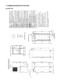
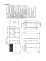
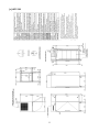
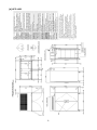
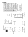
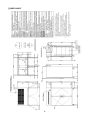
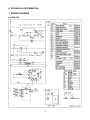
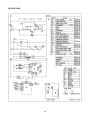
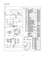
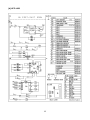
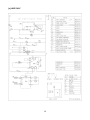
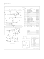
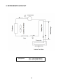
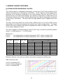
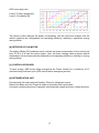
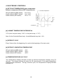
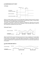
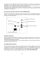
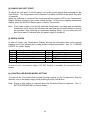
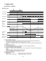
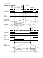
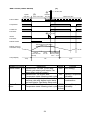
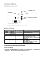
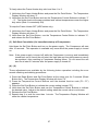
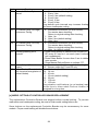
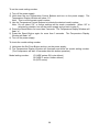
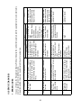
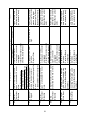
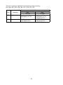
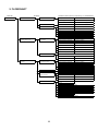
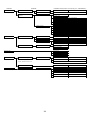
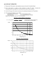
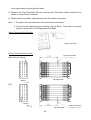
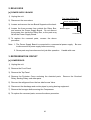
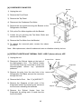
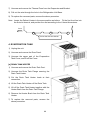
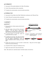
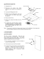
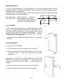
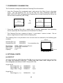
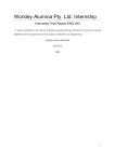
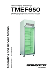
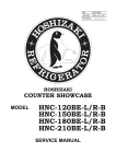
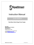
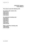
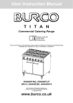
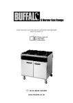
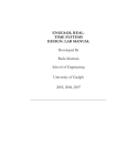
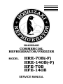
NO. R003-746 ISSUED: DEC. 11, 2007 REVISED: DEC. 1, 2008 HOSHIZAKI COMMERCIAL REFRIGERATOR/FREEZER MODEL HRE-70B(-F) HRE-140B(-F) HFE-70B HFE-140B SERVICE MANUAL CONTENTS PAGE I. GENERAL INFORMATION---------------------------------------------------------------------------1 1. SAFETY INSTRUCTIONS--------------------------------------------------------------------------1 2. DIMENSIONS/SPECIFICATIONS----------------------------------------------------------------3 [a] HRE-70B--------------------------------------------------------------------------------------------3 [b] HRE-140B------------------------------------------------------------------------------------------4 [c] HFE-70B--------------------------------------------------------------------------------------------5 [d] HFE-140B------------------------------------------------------------------------------------------6 [e] HRE-70B-F-----------------------------------------------------------------------------------------7 [f] HRE-140B-F---------------------------------------------------------------------------------------8 II. TECHNICAL INFORMATION------------------------------------------------------------------------9 1. WIRING DIAGRAM-----------------------------------------------------------------------------------9 [a] HRE-70B--------------------------------------------------------------------------------------------9 [b] HRE-140B---------------------------------------------------------------------------------------- 10 [c] HFE-70B------------------------------------------------------------------------------------------ 11 [d] HFE-140B---------------------------------------------------------------------------------------- 12 [e] HRE-70B-F--------------------------------------------------------------------------------------- 13 [f] HRE-140B-F------------------------------------------------------------------------------------- 14 2. REFRIGERATION CIRCUIT--------------------------------------------------------------------- 15 3. ENERGY SAVING FEATURES------------------------------------------------------------------ 16 [a] FRAME HEATER ENERGIZING CONTROL-------------------------------------------- 16 [b] INTERIOR DC FAN MOTOR---------------------------------------------------------------- 17 [c] CONTROLLER BOARD---------------------------------------------------------------------- 17 [d] REFRIGERATION UNIT---------------------------------------------------------------------- 17 4. ELECTRONIC CONTROLS---------------------------------------------------------------------- 18 [a] SET POINT TEMPERATURE--------------------------------------------------------------- 18 [b] CABINET TEMPERATURE DIFFERENTIAL-------------------------------------------- 18 [c] DEFROST CYCLE----------------------------------------------------------------------------- 18 [d] DEFROST COMPLETION TEMPERATURE-------------------------------------------- 18 [e] TEMPERATURE DISPLAY CYCLE-------------------------------------------------------- 18 [f] COMPRESSOR SOFT START-------------------------------------------------------------- 19 [g] HIGH PRESSURE SWITCH----------------------------------------------------------------- 19 [h] CHECKING AND ADJUSTING SET POINT TEMPERATURE---------------------- 20 [i] MANUAL DEFROST--------------------------------------------------------------------------- 20 [j] FRAME HEATER SETTING----------------------------------------------------------------- 20 [k] CANCELLING SOFT START---------------------------------------------------------------- 21 [l] ERROR CODES-------------------------------------------------------------------------------- 21 [m] CONTROLLER BOARD MODEL SETTING-------------------------------------------- 21 5. TIMING CHART------------------------------------------------------------------------------------- 22 [a] STARTUP - CONTROL----------------------------------------------------------------------- 22 [b] DEFROST---------------------------------------------------------------------------------------- 23 6. BUTTON OPERATION---------------------------------------------------------------------------- 25 [a] OPERATION PANEL LAYOUT-------------------------------------------------------------- 25 [b] BASIC OPERATION--------------------------------------------------------------------------- 25 [c] CHECKING AND DELETING ERROR RECORDS------------------------------------ 25 [d] ADJUSTING OPERATION SETTINGS--------------------------------------------------- 26 [e] MODEL SETTING AT CONTROLLER BOARD REPLACEMENT------------------ 28 III. SERVICE DIAGNOSIS----------------------------------------------------------------------------- 30 1. ERROR CODES------------------------------------------------------------------------------------ 30 2. FLOWCHART---------------------------------------------------------------------------------------- 33 3. COMPONENTS------------------------------------------------------------------------------------- 35 4. CONTROLLER BOARD--------------------------------------------------------------------------- 37 [a] SERVICING CONTROLLER BOARD----------------------------------------------------- 37 [b] CHECKING THERMISTOR------------------------------------------------------------------ 38 IV. REMOVAL AND REPLACEMENT OF COMPONENTS----------------------------------- 39 1. CONTROLLER BOARD AND THERMISTOR----------------------------------------------- 39 [a] REMOVAL OF CONTROL BOX------------------------------------------------------------ 39 [b] REPLACEMENT OF CONTROL BOX---------------------------------------------------- 39 [c] THERMISTOR----------------------------------------------------------------------------------- 39 2. RELAY BOX------------------------------------------------------------------------------------------ 41 [a] POWER SUPPLY BOARD------------------------------------------------------------------- 41 3. REFRIGERATION CIRCUIT--------------------------------------------------------------------- 41 [a] COMPRESSOR--------------------------------------------------------------------------------- 41 [b] CONDENSER AND DRIER------------------------------------------------------------------ 42 [c] EVAPORATOR---------------------------------------------------------------------------------- 42 [d] CONDENSER FAN MOTOR----------------------------------------------------------------- 43 [e] DEFROST HEATER AND THERMAL FUSE (HFE)------------------------------------ 43 4. EVAPORATION TANK----------------------------------------------------------------------------- 44 [a] DRAIN TANK HEATER------------------------------------------------------------------------ 44 [b] THERMOSTAT---------------------------------------------------------------------------------- 45 [c] THERMAL FUSE-------------------------------------------------------------------------------- 45 5. AIR DUCT--------------------------------------------------------------------------------------------- 45 [a] AIR DUCT---------------------------------------------------------------------------------------- 45 [b] INTERIOR FAN MOTOR--------------------------------------------------------------------- 46 6. DOOR PARTS--------------------------------------------------------------------------------------- 46 [a] DOOR HANDLE-------------------------------------------------------------------------------- 46 [b] HINGE SPACER-------------------------------------------------------------------------------- 47 [c] LIFT HINGE-------------------------------------------------------------------------------------- 47 [d] DOOR GASKET-------------------------------------------------------------------------------- 47 7. CONDENSER CLEANING PAN----------------------------------------------------------------- 48 8. OPTIONAL PARTS--------------------------------------------------------------------------------- 48 [a] HINGE KIT--------------------------------------------------------------------------------------- 48 [b] GASTRONOME PAN RAIL------------------------------------------------------------------ 49 ii I. GENERAL INFORMATION 1. SAFETY INSTRUCTIONS The following instructions contain important safety precautions and should be strictly observed. The terms used here are defined as follows: WARNING: There is a possibility of death or serious injury to the service person and a third party or the user due to improper service operations or defects in serviced products. CAUTION: There is a possibility of injury to the service person and a third party or the user or damage to their property* due to improper service operations or defects in serviced products. * The term “damage to their property” here refers to extensive damage to household effects, houses and pets. WARNING 1. Always ask the user to keep children away from the work area. They may be injured by tools or disassembled products. 2. When there is no need to energize the unit during disassembly or cleaning, be sure to unplug the unit or disconnect the main power supply before servicing the unit to prevent electric shocks. 3. If the unit must be energized for inspection of the electric circuit, use rubber gloves to avoid contact with any live parts resulting in electric shocks. 4. Keep the following in mind when servicing the refrigeration circuit: (1)Be sure to recover the refrigerant. Do not discharge it into the atmosphere. It will affect the environment. (2)Check for any flames in the vicinity, and ensure good ventilation. (3)If the refrigerant should leak in servicing, immediately put out any fire used in the vicinity. (4)When unbrazing the refrigeration circuit connections, check that the circuit is completely evacuated. The refrigerant may produce a poisonous gas when coming in contact with an open flame. (5)Do not braze in an enclosed room to prevent carbon monoxide poisoning. (6)In case of a refrigerant leak, locate and repair the leaking part completely before recharging the refrigerant and checking for further leaks. If the leaking part cannot be located, be sure to check again for further leaks after recharging the refrigerant. Leaked refrigerant may produce a poisonous gas when coming in contact with an open flame of a gas cooking stove or a fan heater. (7)Before servicing, check the surface temperature of the refrigeration circuit to prevent a burn. 5. Keep the following in mind when making electrical connections: (1)Check for proper earth connections, and repair if necessary to prevent electric shocks. (2)Always use service parts intended for the applicable model for replacement of defective parts. Use proper tools to secure the wiring. Otherwise abnormal operation or trouble may occur and cause electric leaks or fire. (3)Check for proper part installations, wiring conditions and soldered or solderless terminal connections to avoid fire, heat or electric shocks. (4)Be sure to replace damaged or deteriorated power cords and lead wires to prevent fire, heat or electric shocks. (5)Cut-off lead wires must be bound using closed end connectors or the like, with their closed ends up to avoid entrance of moisture that could lead to electric leaks or fire. (6)After servicing, always use a megohmmeter (500V DC) to check for the insulation resistance of at least 1 megohm between the live part (attachment plug) and the dead metal part (earth terminal). (7)Do not service the electrical parts with wet hands to prevent electric shocks. (8)The capacitors used for the compressor and other components may be under high voltage and should be discharged properly before servicing. CAUTION 1. After servicing, follow the instructions below: (1)Always check the unit for proper operation before finishing services. (2)Be sure to reassemble the parts completely. Loose assembly of such parts as control box cover may cause entrance of vermins resulting in a short circuit between terminals and possible ignition. 2. DIMENSIONS/SPECIFICATIONS [a] HRE-70B [b] HRE-140B [c] HFE-70B [d] HFE-140B [e] HRE-70B-F [f] HRE-140B-F II. TECHNICAL INFORMATION 1. WIRING DIAGRAM [a] HRE-70B [b] HRE-140B 10 [c] HFE-70B 11 [d] HFE-140B 12 [e] HRE-70B-F 13 [f] HRE-140B-F 14 2. REFRIGERATION CIRCUIT Refrigerant: HFC-134a (HRE series) HFC-404A (HFE series) 15 3. ENERGY SAVING FEATURES [a] FRAME HEATER ENERGIZING CONTROL The Frame Heater is energized intermittently to keep the Front Frame surfaces at the optimum temperature for preventing condensation. As the optimum surface temperature depends on the ambient temperature, the ratio between ON time and OFF time is determined by the difference between the ambient temperature (measured by the Temperature Sensor built in the Controller Board) and the cabinet temperature (measured by the Interior Thermistor). This duty ratio has eight patterns and is updated every two minutes. The duty ratios are sorted into seven levels (HRE series) or six levels (HFE series) depending on the difference between the ambient and cabinet temperatures. The higher levels at the same ambient and cabinet temperatures mean the higher duty ratios. The unit is factory adjusted to level 2. The user is allowed to choose between levels 2 and 3 only, and service persons between levels 0 - 6 (HRE series) or 1 - 6 (HFE series). [Reference] Level 2: No condensation at ambient temperature 35°C, relative humidity 70% Level 3: No condensation at ambient temperature 35°C, relative humidity 80% Duty Ratio ON time OFF time (%) 12.5 25 37.5 50 62.5 75 87.5 100 (sec) 15 30 45 60 75 90 105 120 (sec) 105 90 75 60 45 30 15 0 Ambient temp - cabinet temp HRE series HFE series Level 3 Level 2 Level 3 Level 2 5 or less 14 or less 9 or less 23 or less 5 - 10 14 - 19 9 - 16 23 - 30 10 - 14 19 - 24 16 - 23 30 - 37 14 - 19 24 - 28 23 - 30 37 - 44 19 - 24 28 - 33 30 - 37 44 - 52 24 - 28 33 - 37 37 - 44 52 - 59 28 - 33 37 - 41 44 - 52 59 - 66 33 or more 41 or more 52 or more 66 or more [Relations between duty ratio and ambient and cabinet temperature differences] HRE series duty ratio Level 0: Constantly OFF Level 2: Factory adjustment Level 6: Constantly ON 16 HFE series duty ratio Level 2: Factory adjustment Level 6: Constantly ON The heater control reduces the power consumption, and the less heat invasion into the cabinet improves the refrigeration unit operating efficiency, resulting in significant energy saving effects. [b] INTERIOR DC FAN MOTOR The highly efficient DC brushless motor reduces the power consumption of the motor body from 21 W to 4 W with the same output. Also, the lower heating value prevents cabinet temperature rise and improves the refrigeration unit operating efficiency, resulting in energy saving effects. [c] CONTROLLER BOARD To save energy, HRE series stops energizing the Frame Heater for a maximum of 15 minutes during a defrost cycle (HFE series has an energizing control). [d] REFRIGERATION UNIT Provided with the best matched Capillary Tubes for refrigerant control. Plastic Unit Base and Unit Frame in shape to minimize heat input/output. Corrosion resistant aluminum Evaporator with boehmite treated and clear coated surfaces. 17 4. ELECTRONIC CONTROLS [a] SET POINT TEMPERATURE (mean temperature between compressor ON and OFF temperatures) 3.7 K 0 to +16°C -6 to +12°C -25 to -7°C Interior Thermistor Temperature Off-cycle defrost (HRE series): Heater defrost (HRE-F series): Heater defrost (HFE series): Set Point Temperature Time Compressor ON OFF [b] CABINET TEMPERATURE DIFFERENTIAL 3.7 K (from “set point temp - 2.0 K” to “set point temp + 1.7 K”) Note: On the Controller Board only. Actual differential may be 4 - 6 K. [c] DEFROST CYCLE Every 6 hours (from the beginning of a cycle to the beginning of the next cycle) [d] DEFROST COMPLETION TEMPERATURE Off-cycle defrost (HRE series): Heater defrost (HRE-F series): Heater defrost (HFE series): +3°C +30°C +20°C [e] TEMPERATURE DISPLAY CYCLE The Temperature Display Window renews its cabinet temperature display every 30 seconds. The display remains the same for 30 seconds even if the actual temperature changes in the meantime. During a defrost cycle, the Temperature Display Window indicates “dF”. 18 [f] COMPRESSOR SOFT START 1) Startup Power ON 3 min 20 sec ON Compressor Condenser Fan Motor OFF ON Interior Fan Motor OFF ON Cabinet Temp. Display OFF When the power supply is turned on, the Temperature Display Window shows the cabinet temperature, but the Compressor and Condenser Fan Motor start up with a 3 minute delay. Then, the Interior Fan Motor starts up 20 seconds later. This delay is intended to minimize the difference between the high-side and low-side pressures and to reduce the load on the Compressor so that it can start easily in case of a short (especially instantaneous) power failure. 2) Normal Control Interior Thermistor Compressor Condenser Fan Motor Set Point ON 2.5 min OFF 2.5 min When the Compressor turns off during normal control, it has a mandatory 2.5 minute delay before startup. For example, if the Compressor turns off by its Thermistor and the Door is opened immediately after (causing the cabinet temperature to immediately exceed the restart temperature), the Compressor will still not start until 2.5 minutes have passed since its shutdown. [g] HIGH PRESSURE SWITCH Pressure Switch Set Point Compressor Condenser Fan Motor ON Min 6 min OFF 19 6 min All models are provided with a High Pressure Sensor to monitor the condensing temperature. If the high-side pressure rises to operate the High Pressure Sensor, the Compressor will not restart for at least 6 minutes to protect itself. HFE series is also equipped with a backup High Pressure Switch. If the Condensing Temperature Thermistor becomes defective, the High Pressure Switch operates to stop and protect the Compressor. [h] CHECKING AND ADJUSTING SET POINT TEMPERATURE Press the Set Point Button to display the set point temperature on the Temperature Display Window. To change the set point temperature, hold down the Set Point Button and press the Temperature Control Button. Frame Heater Button Reset Button Manual Defrost Button Set Point Button Temperature Control Button Temperature Display Window [i] MANUAL DEFROST When the Manual Defrost Button is pressed for more than 5 seconds, the unit will start a manual defrost cycle. The unit will start repeating automatic defrost cycles 6 hours after the Manual Defrost Button is pressed. To cancel the manual defrost cycle, turn off the power supply. Wait for at least 30 seconds before turning the power back on. [j] FRAME HEATER SETTING The duty ratio of the Frame Heater is controlled. The unit is factory adjusted to the duty ratio level 2 with the lamp on the Frame Heater Button off. If condensation occurs at the installation site, press the Frame Heater Button for more than 3 seconds to change the duty ratio level from 2 to 3. Then, the lamp on the Frame Heater Button will illuminate. To de-energize the Frame Heater (HRE series only), see “6. BUTTON OPERATION”. 20 [k] CANCELING SOFT START To cancel the “soft start” (3 minute delay), turn on the power supply while pressing the Set Point Button. The Compressor and Condenser Fan Motor will start at the same time after 10 seconds. When the soft start is cancelled, the illuminated seven segment LED on the Temperature Display Window changes to the model setting number. To resume the cabinet temperature display, press the Set Point Button again or wait for 30 seconds. Note: If the power supply is turned off while the Compressor is running and immediately turned back on to cancel the soft start, the high-side and low-side pressures cannot be equalized, often resulting in Compressor starting failure. Do not cancel the soft start for at least 2.5 minutes after the power supply is turned off. [l] ERROR CODES In case of trouble, the Temperature Display Window will alternately flash every second between one of the following error codes and the cabinet temperature. See “III. 1. ERROR CODES” for further details. Code E1 E2 E3 E4 E5 Error Cabinet Temperature Too High Cabinet Temperature Too Low Defrost Cycle Too Long Abnormal High-Side Pressure Interior Thermistor Defective Code E7 E8 E9 EA Ed Error Condenser Clogged Defrost Thermistor Defective Clog Thermistor Defective EEPROM Write Error EEPROM Verify Error In case of error, an external output (12V DC) function is available for connection with a buzzer. [m] CONTROLLER BOARD MODEL SETTING To indicate the Controller Board model setting number on the Temperature Display Window, turn on the power supply while pressing the Set Point Button. Note: Proper model setting is required when the Controller Board is replaced. See “6. BUTTON OPERATION” for further details. 21 5. TIMING CHART [a] STARTUP - CONTROL HRE, HFE series (2) 3 min (3) 20 sec Power Supply Temp Display (1) Frame Heater Compressor Condenser Fan Motor Interior Fan Motor Interior Thermistor Temp Set Point Temp + 1.7 K Set Point Temp Set Point Temp - 2.0 K Evaporation Signal (4) Evaporation Pan Heater Evaporation Pan Thermostat (1) Frame Heater Control Intermittent energization by difference between ambient and cabinet temperatures. Energization time has 8 patterns (duty ratio 12.5% - 100%). Duty ratio is updated every 2 min, except previous ratio is maintained during defrost cycle. (2) Standby at Startup Only temperature indication is available for 3 min (not a sign of failure). (3) Interior Fan Motor Delay at Startup Interior Fan Motor and Frame Heater will not operate for 20 sec after Compressor starts. Interior Fan Motor OFF after End of Control Interior Fan Motor will not operate for 2 min. (4) Evaporation Signal HRE series: Cam Timer, for 7 min every 8 hrs HRE-F series, HFE series: Defrost start signal, every 6 hrs 22 [b] DEFROST HRE series (Off-cycle defrost) Update duty ratio (1) 20 sec OFF Max 15 min OFF Maintain duty ratio Update duty ratio Frame Heater Compressor Condenser Fan Motor Interior Fan Motor Detects end of cycle (3°C) Defrost (Interior) Thermistor Temp Temp Display Defrost (until Thermistor detects) Temp HFE series Update duty ratio Temp and "dF" alternately (3) Temp (2) Maintain previous duty ratio 20 sec OFF Update duty ratio Frame Heater Compressor Condenser Fan Motor Interior Fan Motor Defrost Heater Duct Heater Detects end of cycle (20°C) Defrost Thermistor Temp Defrost (until Thermistor detects) Temp Display Temp Drain 0 min "dF" 23 Interior Display FM delay delay 5 min 3 min Temp (2) HRE-F series (Heater defrost) Update duty ratio 20 sec OFF (3) (1) Max 15 min OFF Maintain duty ratio Update duty ratio Frame Heater Compressor Condenser Fan Motor (4) 5 sec ON Interior Fan Motor Defrost Heater Detects end of cycle (30°C) Defrost (Interior) Thermistor Temp Temp Display Defrost (until Thermisto detects) Temp Drain 5.5 min Interior Display delay 5 min 3 min FM delay "dF" Subject of Control Description Frame Heater (1) Remains OFF for max 15 min after defrost cycle starts (until Interior Fan Motor delay ends at longest) (2) Remains OFF for 20 sec after Compressor starts following drain cycle (3) Duty ratio is not updated and maintains previous ratio after defrost cycle starts and until Interior Fan Motor delay ends Interior Fan (4) Remains ON for 15 sec after Motor Compressor starts following drain cycle 24 Temp Model Purpose HRE Save energy HFE HFE Improve Compressor startability Prevent condensation HRE-F Improve Compressor (Heater startability defrost) 6. BUTTON OPERATION [a] OPERATION PANEL LAYOUT Frame Heater Button Reset Button Manual Defrost Button Set Point Button Temperature Control Button Temperature Display Window [b] BASIC OPERATION Condition Constant Constant Constant Error Constant Button Pressing Duration Set Point — — Set Point Temp Control Manual Defrost Long (5 sec) Reset Short Frame Heater Long (3 sec) Function Indicate set point temp while depressed Change set point temp Start manual defrost Cancel error code indication (not available on some errors) With more than one error, press to cancel one by one Change Frame Heater level High: Lamp ON (raise default duty ratio by 1 level) Low: Lamp OFF (default) [c] CHECKING AND DELETING ERROR RECORDS To check error records: 1) Press the Reset Button and Set Point Button at the same time for 5 seconds (Reset Button first). The Temperature Display Window will show “F0”. 25 2) Press the Temperature Control Buttons until “F6” appears. 3) Press the Reset Button to flash the error records in the order of occurrence. “– –” will appear if no error is recorded. 4) Press the Manual Defrost Button to return to “F6”. 5) Repeat step 1) to indicate the cabinet temperature. To delete error records: 1) Follow steps 1) to 3) above. 2) Press the Reset Button for 5 seconds to flash “– –”. 3) Follow steps 4) to 5) above. Note: 1. Do not perform any other button operation until the Temperature Display Window shows from “F0” to “FF” before showing “F6”. Otherwise, the basic settings will change and may cause malfunction. In case of misoperation, see the list in “[d] ADJUSTING OPERATION SETTINGS” to restore the default settings. 2. Repeated errors are stored as one record. For example, errors in the order of E7, E7, E7, E4, E7 are recorded as E7, E4, E7. [d] ADJUSTING OPERATION SETTINGS The following settings are adjustable: (1) (2) (3) (4) (5) (6) (7) (8) Set Point Temperature Frame Heater Duty Ratio Level Soft Start Cancelation Automatic Defrost Cycle Interval E1 (Cabinet Temperature Too High) Occurrence Timing E2 (Cabinet Temperature Too Low) Occurrence Timing Buzzer Output (External Output) Defrost Backup Timer Except (1) and (2), the default settings are optimal to meet the specifications. To prevent unexpected malfunction, do not adjust them unless necessary. (1) Set Point Temperature Hold down the Set Point Button, use the Temperature Control Buttons to adjust to the desired set point temperature, and release the Set Point Button. (2) Frame Heater Duty Ratio Level If condensation occurs on the Front Frame: Press the Frame Heater Button for 3 seconds to illuminate the lamp on the button (the duty ratio is raised by 1 level). 26 To freely select the Frame Heater duty ratio level from 1 to 6: 1) Hold down the Frame Heater Button and press the Set Point Button. The Temperature Display Window will show “2”. 2) Hold down the Set Point Button and use the Temperature Control Buttons to indicate “1” - “6”. The higher levels at the same ambient and cabinet temperatures mean the higher duty ratios (level 6 is constantly ON). To keep the Frame Heater OFF (HRE series only): 1) Hold down the Frame Heater Button and press the Set Point Button. The Temperature Display Window will show “2”. 2) Hold down the Set Point Button, use the Temperature Control Button to indicate “0”, and release the Set Point Button. (3) Soft Start Cancelation (for immediate startup of Compressor) Hold down the Set Point Button and turn on the power supply. The Compressor will start after 10 seconds. This operation is available only once when the power supply is turned on. Note: If the power supply is turned off while the Compressor is running and immediately turned back on to cancel the soft start, the high-side and low-side pressures cannot be equalized, often resulting in Compressor starting failure. Do not cancel the soft start for at least 2.5 minutes after the power supply is turned off. (4) - (9) These adjustments are available by the following button operation including the error records checking and deleting procedures: 1) Press the Reset Button and Set Point Button at the same time for 5 seconds (Reset Button first). The Temperature Display Window will show “F0”. 2) Press the Temperature Control Buttons until the desired function code (F0 - FF) appears. 3) Press the Set Point Button to indicate the current setting (except “F6”). 4) Hold down the Set Point Button and use the Temperature Control Buttons to indicate the desired value. Adjust to the default setting when the correct value is not known. 5) Release the Set Point Button. 6) Repeat step 1) or wait for more than 1 minute. The Temperature Display Window will show the cabinet temperature. 27 Code Function F0 A utomatic Defrost Cycle Interval F3 F4 F6 Fb FC Indication with Set Point Button – –: No automatic defrost cycle 3: Every 3 hrs 6: Every 6 hrs (default setting) 8: Every 8 hrs 12: Every 12 hrs 24: Every 24 hrs Long defrost cycle intervals may increase frosting and cause inadequate cooling. E1 (Cabinet Temp Too High) 0: Immediate occurrence (no error record) Occurrence Timing For remote alarm checking. Return to original setting after checking. 1: After 1 hr 2: After 2 hrs (default setting) 3: After 3 hrs 0: Immediate occurrence (no error record) E2 (Cabinet Temp Too Low) Occurrence Timing For remote alarm checking. Return to original setting after checking. 1: After 1 hr (default setting) Checking/Deleting Error 1)Press Reset Button to indicate error records (E1 EE) every 0.5 sec for 1 sec each (max 8 records Records per compartment). 2)Press Reset Button for more than 5 sec to delete error records. 3)Press Manual Defrost Button to indicate “F6”. Buzzer Output (External AL: Buzzer output for all errors (default setting) Output) 1.2: Buzzer output for E1 and E2 only Defrost Backup Timer (duration – –: No backup (no E3 occurrence) until forced de-energization of 0.4: 24 min Defrost Heater) 0.7: 40 min 1: 60 min (default setting) 1.3: 80 min 1.7: 100 min 2: 120 min Long duration until backup (or no backup) may cause fuse to blow when Defrost Heater is energized for a long time. [e] MODEL SETTING AT CONTROLLER BOARD REPLACEMENT The replacement Controller Boards are shipped without model setting. To prevent malfunction and inadequate cooling, be sure to finish model setting before use. Some buttons on the replacement Controller Boards may be unnecessary for some models. Proper model setting will disable those buttons. 28 To set the mode setting number: 1) Turn off the power supply. 2) Hold down the two Temperature Control Buttons and turn on the power supply. The Temperature Display Window will show “01”. Note: This is not the preset model number. 3) Use the Temperature Control Buttons to indicate the desired model number. Note: Do not select “00”, or further settings will be made unavailable. When “00” is selected by mistake, turn off the power supply and go back to step 2). 4) Press the Reset Button for more than 3 seconds. The Temperature Display Window will flash “rc”. 5) Press the Reset Button again for more than 3 seconds. The Temperature Display Window will flash “oF”. 6) Turn off the power supply. To check the model setting number: 1) Hold down the Set Point Button and turn on the power supply. 2) The Temperature Display Window will illuminate and show the model setting number. (The Compressor will start 10 seconds after this button operation.) Model setting number: 1D (HRE series: Off-cycle defrost) 0D (HRE-F series: Heater defrost) 29 (HFE series) 29 30 Error Description Possible Cause Reset Component Condition E1 Cabinet Temp Cabinet temp stays 10K above -Compressor control error -Ambient temp too Press Reset Button. high Automatically resets Too High set point for 2 hrs (available -Compressor defective after power is turned on and -Gap between Door when cabinet temp -Refrigeration circuit defective (ex. gas leak) and cabinet drops to lower limit. cabinet temp drops to lower limit). -Interior Thermistor -Door opened too defective frequently -Too many warm items inside E2 Cabinet Temp Cabinet temp stays 5K below -Compressor control error -Ambient temp too low Press Reset Button. Automatically resets Too Low set point for 1 hr. -Interior Thermistor -Too many frozen defective items inside when cabinet temp rises to upper limit. E3 Defrost Cycle Defrost Heater remains -Heater control error Press Reset Button (no -Door opened too frequently, causing automatic reset). Too Long energized for 1 hr and is forcibly -Heater defective excessive Evaporator (HFE series de-energized. -Thermal Fuse circuit open frosting only) -Defrost Thermistor defective -Ambient temp too E4 Abnormal High pressure is detected 5 -Condenser Fan Motor Press Reset Button (no defective high automatic reset). High-Side or more times in 1 hr (4 times Pressure within 1 hr after 1st detection). -Dirty Air Filter Clog Thermistor -Clog Thermistor defective * See table below for set point. Code In case of trouble, the Temperature Display Window indicates the cabinet temperature and the applicable error code alternately every 1 second (even in a defrost cycle). Except EA and Ed, there is no need to restart the unit to reset errors. 1. ERROR CODES III. SERVICE DIAGNOSIS 31 Error Ed EEPROM Verify Error EA EEPROM Write Error E9 Clog Thermistor Defective E8 Defrost Thermistor Defective E7 Condenser Clogged E5 Interior Thermistor Defective Code Possible Cause Component Condition -Interior Thermistor circuit open, connector unplugged -Interior Thermistor circuit shorted, dusty connector Interior Thermistor circuit is open or shorted for 10 min or more. Note: For either reason, Compressor will operate continuously. Be careful with frozen refrigerator compartment. Surface temp of Condenser -Condenser Fan Motor -Ambient temp too piping (U bend at center or defective high outlet) stays above set point for -Dirty Air Filter 5 min. * See table below for set point. Defrost Thermistor circuit is -Defrost Thermistor circuit open, connector open or shorted for 10 min or unplugged more. -Defrost Thermistor circuit shorted, dusty connector Clog Thermistor circuit is open -Clog Thermistor circuit open, connector or shorted for 10 min or more. unplugged -Clog Thermistor circuit shorted, dusty connector Abnormal value is detected -Controller Board defective in EEPROM reading/writing (Controller Board hardware -Controller Board malfunction problem). Inconsistency is detected -Controller Board defective in setting information used (Controller Board software -Controller Board malfunction problem). Description Turn power off and back on after 30 sec (no automatic reset). Turn power off and back on after 30 sec (no automatic reset). Automatically resets after cause is removed (Reset Button will not work). Automatically resets when Clog Thermistor senses temp lower than set point (Reset Button will not work). Automatically resets after cause is removed (Reset Button will not work). Reset Press Reset Button after removing cause (no automatic reset). The error cords are indicated in the following order of priority: EA > Ed > E5 > E8 > E9 > E4 > E7 > E3 > E1 > E2 Error Detection E4 High pressure E7 Clog HRE R-134a Clog Thermistor Immediately at 78°C Clog Thermistor 5 min above 56°C 32 Set Point HFE R-404A Clog Thermistor Immediately at 73°C 5 min above 70°C Clog Thermistor 5 min above 56°C 2. FLOWCHART PROBLEM No refrigeration PROBLEM Compressor will not start POSSIBLE CAUSE (numbers corresponding to "3. COMPONENTS") No temp indication ①Safety Breaker OFF ②Power Supply Board Controller Board 2V DC output ③Controller Board Open circuit, connector unplugged EA, Ed error indication ③Controller Board Defective No error indication ⑤Interior Thermistor Abnormal resistance, bad contact ⑥Clog Thermistor Abnormal resistance, bad contact ⑧Pressure Switch (HFE) Short circuit, defective ④Relay Output ⑨Compressor Winding open, electrical part defective Compressor starts and stops E4 error indication/record Ambient temp too high immediately (within 3 min) (high pressure) Condensing capacity insufficient Heat source, ventilation Air Filter Clogged ⑬Condenser Fan Motor Locked, open circuit ④Relay Condenser Fan Motor output ⑥Clog Thermistor Abnormal resistance, bad contact ⑧Pressure Switch (HFE) Defective No error indication See "E4 error indication/record" above ⑤Interior Thermistor Location ⑨Compressor Locked, etc Compressor runs with no E7 error indication/record Ambient temp too high refrigeration (high condensing temp) Condensing capacity insufficient Heat source, ventilation Air Filter Clogged ⑬Condenser Fan Motor Locked, open circuit ④Relay Condenser Fan Motor output E8 error indication/record ⑦Defrost Thermistor Abnormal resistance, bad contact E3 error indication/record ⑦Defrost Thermistor Abnormal resistance (frosted evaporator) ⑮Defrost Heater Open circuit, defective ④Relay Defrost Heater output ⑯Thermal Fuse Blown No error indication Internal load too large Door gap ⑤Interior Thermistor Location ⑭Interior Fan Motor Open circuit, defective ②Power Supply Board Interior Fan Motor 12V DC output ⑰Refrigeration circuit clogged Capillary, Drier ⑱Refrigerant leak ⑨Compressor 33 Defective PROBLEM Poor refrigeration PROBLEM Slow refrigeration POSSIBLE CAUSE (numbers corresponding to "3. COMPONENTS") Set point is reached Interior overloaded Set point is not reached See "Compressor runs with no refrigeration" above Normal temp indication with poor Interior overloaded refrigeration Heat load inside Frosted evaporator Excessive refrigeration Compressor runs continuously Compressor stops ⑭Interior Fan Motor Open circuit, defective ②Power Supply Board Interior Fan Motor 12V DC output ⑤Interior Thermistor Abnormal resistance, bad contact, location ③Controller Board Defective Defrost cycle setting readjusted Too long ⑦Defrost Thermistor Abnormal resistance ⑮Defrost Heater Open circuit, defective ④Relay, Relay Board Defrost Heater output ⑯Thermal Fuse Blown E5 error indication/record ⑤Interior Thermistor Open circuit, short circuit High temp indication ⑤Interior Thermistor Location Normal temp indication ⑤Interior Thermistor Abnormal resistance ③Controller Board Defective No error indication Cold air outlet loaded Cold air inlet blocked Ambient temp too low Abnormal noise ⑨Compressor ⑬Condenser Fan Motor ⑭Interior Fan Motor Condensation Frame Heater is not energized No error indication * Intermittent energizing control is working. Monitor for at least 2 min. Frame Heater is energized Water leak from rear Drain water is not evaporated Sheath Heater is not energized 34 Duty ratio setting improper Readjust ②Power Supply Board Frame Heater 100V AC output ③Controller Board Defective Duty ratio setting too low Raise duty ratio level ⑪Cam Timer (HRE) Open circuit, defective ⑫Thermostat Contact ④Relay Output ⑯Thermal Fuse Conductivity ⑩Sheath Heater Open circuit, defective 3. COMPONENTS CHART NO. COMPONENT ① Safety Breaker ② Power Supply Board (in Relay Box) ③ Controller Board ④ Relay ⑤ Interior Thermistor CHECK Safety Breaker trips Safety Breaker splashed with water Open circuit Input/output (Controller Board, Interior Fan Motor) Input: 115V AC Output: 12V DC Controller Board output - K1 Connector No. 1, 2 Interior Fan Motor - See wiring label Frame Heater voltage (K2 Connector No. 1, 3) Heater ON: 0V Heater OFF: 115V Switches every 2 min Connector/pin disconnected Connector dusty/dirty 7 segment display partially/totally off Electronic parts defective/burnt out Ambient Temp Sensor damaged (Frame Heater will be continuously energized) Relay, Relay Board output (12V DC) Fast-on terminal/pin disconnected Connector dusty/dirty Open circuit Output to each load Check with wiring diagram/timing chart Abnormal noise Location (holder in front of Evaporator) Disconnected, replaced with Defrost Thermistor, etc Incorrect temp indication Short circuit (temp displayed as "HH") ⑥ Clog Thermistor Open circuit (temp displayed as "-60") Abnormal resistance Short circuit ⑦ Defrost Thermistor Open circuit Location (plug in from Evaporator front) Disconnected, replaced with Interior Thermistor, etc Abnormal resistance Short circuit ⑧ Pressure Switch ⑨ Compressor Open circuit Terminal splashed with water Terminal dusty/dirty Conductivity between contacts Resistance between terminals Compressor Winding Resistance (ȍ) Primary Secondary FR8.5G 8.9 12.0 SC18G 3.7 14.1 SC12CL 5.0 13.7 SC18CL 3.7 14.1 Insulation resistance 1Mȍ or more at 500V Abnormal noise Insufficient compression (discharge temp too low) 35 REMEDY Locate earth leakage/short circuit Dry and replace if necessary Correct or replace Replace Replace Correct Remove Replace Replace Replace Replace Correct Remove Correct Replace Replace Correct Immerse in ice water to check resistance (5 - 6.5kȍ) Replace if necessary Clean/dry connector Replace Replace Immerse in ice water to check resistance (150 - 180kȍ) Replace if necessary Clean/dry connector Replace Replace Correct Immerse in ice water to check resistance (5 - 6.5kȍ) Replace if necessary Clean/dry connector Replace Replace Dry and replace if necessary Remove Replace if conductive Replace Replace Replace Replace if no gas leaks CHART NO. COMPONENT ⑨ Compressor ⑩ ⑪ ⑫ ⑬ ⑭ ⑮ ⑯ ⑰ ⑱ CHECK Electrical part defective (constant speed compressor only) - Run/Start Capacitor ruptured/deformed - Capacitor defective Check resistance between terminals Gradually reduces: No problem 0ȍ from start: Defective - Starter defective Loose terminal, no conductivity, damaged - Overload Relay defective Loose terminal, no conductivity, damaged Sheath Heater Open circuit Conductivity Insulation resistance 1Mȍ or more at 500V Cam Timer Fast-on terminal disconnected Coil circuit open Thermostat Open circuit Conductivity Condenser Fan Motor Open circuit Locked (not rotating with voltage) Internal fuse blown (coil not conductive) Abnormal noise Interior Fan Motor Open circuit Locked (not rotating with voltage) Abnormal noise Defrost Heater Open circuit Conductivity Insulation resistance 1Mȍ or more at 500V Thermal Fuse Conductivity Relay contact fused Refrigeration Circuit Operate constantly at 55Hz in operation setting mode Clogged Discharge pressure: High Suction pressure: Low (vacuum) Refrigerant Leak Discharge pressure: Low Suction pressure: High 36 REMEDY Correct Replace Replace Correct Replace Correct Replace if not conductive Correct Replace Replace Replace Correct Replace Replace Correct Replace Replace Replace Replace Relay/Relay Board Replace Capillary/Expansion Valve (Replace Drier at same time) Locate leakage and replace (Replace Drier at same time) 4. CONTROLLER BOARD [a] SERVICING CONTROLLER BOARD 1) If receiving a service call, ask the user to turn off the power supply and turn it back on after 30 seconds, while watching the unit. This will reset the controller, and in some cases normal operation will resume. 2) Keep the following in mind when servicing the Controller Board: * Check that the unit has been earthed properly. If not, the Controller Board will not work properly. * To get static free, always touch the cabinet (earth) before servicing. Electrostatic discharge will cause severe damage to the Controller Board. Also, keep it away from vinyl, plastic or other electrostatically charged products. * Do not touch the reverse side of the Controller Board and tiny electronic devices on it. * The Controller Board and Thermistor can be replaced separately. * Handle the Controller Board by the edges only. Do not push the electric parts and wires. * Do not drop the Controller Board on the floor. * To protect the pattern from damage, place the Controller Board on a flat surface. * The Thermistor and Pressure Switch leads have a thin coating and potentially breakable. Do not tension the leads. * The connectors must not be subjected to tension to prevent disconnection or breakage. After servicing the Controller Board, check for disconnected connectors. * The Thermistor is provided with single-wire leads. Do not bend or stretch them (about 400 mm from the end and at lead connections). * Do not pinch or weigh down the Thermistor and Thermistor leads. The coatings may be broken, resulting in a short circuit. * Keep the Thermistor and Relay Box wires at least 30 mm away from the high voltage (100V AC or more) wires. 3) After replacing the Controller Board, make the following settings: * The replacement Controller Boards are shipped without model setting. To prevent malfunction and failure, be sure to finish model setting before use according to “II. 6. [e] MODEL SETTING AT CONTROLLER BOARD REPLACEMENT”. * Some buttons on the replacement Controller Boards may be unnecessary for some models. Proper model setting will disable those buttons. 37 [b] CHECKING THERMISTOR 1) Remove the Thermistor’s intermediate connector from the Controller Board. 2) Put ice and water in a glass or other container to make 0°C water. Immerse the Thermistor bulb in the water for 5 minutes (at the center of the container). 3) Use the Ω range of the tester to measure the resistance between the Thermistors. 4) If the measured resistance is not within: Interior/Defrost Thermistor 5 - 6.5 kΩ (standard 6 kΩ) Clog Thermistor 150 - 180 kΩ (standard 162 kΩ) replace the Thermistor (see the T-R curve below). T-R Curve (Interior/Defrost Thermistor) ⎧ 1 1 ⎞⎫ ⎛ R = 6 × Exp ⎨3390 × ⎜ − ⎟⎬ ⎝ 273 .15 + T 273 .15 ⎠ ⎭ ⎩ R (kΩ) The graph shows reference values only and may differ from actual values. 60 50 40 30 20 10 0 -50 -40 -30 -20 -10 0 10 Temperature (°C) T-R Curve (Clog Thermistor) R (kΩ) Temperature (°C) 38 20 30 IV. REMOVAL AND REPLACEMENT OF COMPONENTS 1. CONTROLLER BOARD AND THERMISTOR Cover [a] REMOVAL OF CONTROL BOX 1) Lift the Cover off the back of the Control Box. Tab 2) Remove the screw (rear left) securing the Control Box, and remove the Control Box. Screw 3) Disconnect the connectors from the Control Box by pinching both ends of the connectors with thumb and middle finger and unlocking the connectors with forefinger. 4) Remove the four screws of the Control Box, and separate it into the Operation Panel side and box side. 5) Remove the two screws from the Operation Panel side, and remove the Controller Board. [b] REPLACEMENT OF CONTROL BOX 1) Handle the Controller Board with care according to “III. 4. [a] SERVICING CONTROLLER BOARD”. 2) Replace the Controller Board in the reverse order of the removal procedure with the following points in mind: * To replace the Control Box, be sure to hook the two tabs on the grips. * Plug in the connectors until they lock in place. * Keep the wires inside the Rear Cover. 3) Check that the Operation Panel is securely mounted. 4) After replacing the Controller Board, be sure to make model setting. unit will not operate properly, and the Compressor may be damaged. Otherwise, the [c] THERMISTOR 1) Remove the Air Duct inside the cabinet. See “5. [a] AIR DUCT”. 2) Remove the Interior Thermistor Bulb on the ceiling in front of the Evaporator by unhooking the two tabs securing the Thermistor Holder. 3) Remove the Defrost Thermistor Bulb inside the Evaporator Fins by pinching off the Thermistor Holder. 4) Pull out the Thermistors through the hole in the Refrigeration Unit Base. 39 Be careful not to press hard on the bulbs and leads. 5) Remove the Clog Thermistor Bulb by removing the Thermistor Holder located at the center or outlet of the Condenser. 6) Remove the Control Box, and disconnect the Thermistor connectors. Note: 1. To replace the removed parts, reverse the above procedure. 2. To prevent the Evaporator from freezing, use the Bush - Thermistor to securely plug the wiring hole in the Refrigeration Unit Base. Interior Thermistor Bulb Location Interior Thermistor Defrost Thermistor Bulb Location Defrost Thermistor HRE (Off-cycle defrost) Fan Motor Side Bottom HFE Bottom Defrost Thermistor Fan Motor Side 40 2. RELAY BOX [a] POWER SUPPLY BOARD 1) Unplug the unit. Top View of Relay Box 2) Disconnect the connectors. Power Supply Board 3) Loosen and remove the two Board Supports at the back. 4) Loosen the three screws from outside the Relay Box, and remove the Power Supply Board. Do not remove the screws from inside the Relay Box, or the parts may fall off the Power Supply Board. Board Support Screw M4 x 8 5) To replace the removed parts, reverse the above procedure. Note: 1. The Power Supply Board is connected to a commercial power supply. Be sure to disconnect the power supply before servicing. 2. Some parts may have become hot just after operation. Handle with care. 3. REFRIGERATION CIRCUIT [a] COMPRESSOR 1) Unplug the unit. 2) Remove the Front Panel. 3) Remove the Top Panel. 4) Remove the Protector Cover enclosing the electrical parts. Relay, Starting Relay, and other parts. Remove the Overload 5) Recover the refrigerant from the low side Access Valve. 6) Disconnect the discharge and suction pipes by using brazing equipment. 7) Remove the hexagon bolts securing the Compressor. 8) To replace the removed parts, reverse the above procedure. 41 [b] CONDENSER AND DRIER 1) Unplug the unit. 2) Remove the Front Panel. 3) Recover the refrigerant from the low side Access Valve. 4) Unscrew the Condenser. 5) Unscrew the Drier. 6) Disconnect the Condenser from the upper inlet pipe connection using brazing equipment. 7) Remove the Condenser and Drier from the Refrigeration Unit Base, and disconnect them using brazing equipment. 8) To replace the removed parts, reverse the above procedure. Note: The Capillary Tube is directly brazed to the Drier. To prevent brazing material from clogging, be sure to insert the Capillary Tube securely into the point of Stopper before brazing. [c] EVAPORATOR 1) Unplug the unit. 2) Remove the Front Panel. 3) Recover the refrigerant from the low side Access Valve. 4) Remove the Insulation Hoses on the Refrigeration Unit Base. Evaporator using brazing equipment. Disconnect the 5) Remove the Air Duct. 6) Disconnect the Defrost Heater wires. FUSE”. See “[e] DEFROST HEATER AND THERMAL 7) Unscrew and remove the Evaporator. 8) To replace the removed parts, reverse the above procedure. 42 [d] CONDENSER FAN MOTOR Bracket 1) Unplug the unit. 2) Remove the Front Panel. 3) Remove the Top Panel. 4) Disconnect the Condenser Fan Motor. Fan Motor 5) Remove the two screws securing the Bracket on the Refrigeration Unit Base. 6) Pull up the Fan Motor together with the Bracket. 7) Loosen the nut securing the Fan Motor Shaft, and remove the Fan Motor. 8) Remove the Fan Motor from the Bracket. Condenser 9) To replace the removed parts, reverse the above procedure. Note: After replacement, check for abnormal noise or vibration noise by trial run. [e] DEFROST HEATER AND THERMAL FUSE - HRE-F (Heater defrost), HFE 1) Unplug the unit. Thermal Fuse 2) Disconnect the Defrost Heater at the back of the Refrigeration Unit. The Defrost Heater and Thermal Fuse are connected in series and interchangeable without any operational problems. Evaporator 3) Remove the putty from the wire hole in the Defrost Heater Refrigeration Unit Base, and put the connector through the hole. 4) Remove the Air Duct. See “5. [a] AIR DUCT”. 5) Remove the Supports at both ends of the Evaporator bottom by loosening the screws at the front and unhooking the backside. 6) Remove the Defrost Heater from the Evaporator by pulling each U bend from the front to the back. 43 Bracket Support 7) Unscrew and remove the Thermal Fuse from the Evaporator and Bracket. 8) Pull out the wire through the hole in the Refrigeration Unit Base. 9) To replace the removed parts, reverse the above procedure. Note: Locate the Defrost Heater in the same position as before. Fit the first front line into the first slot channel, and position the rest according to the U-bend dimensions. Front Fit into the first slot channel 4. EVAPORATION TANK 1) Unplug the unit. 2) Unscrew and remove the Rear Panel. 3) Unscrew the upper part of the Evaporation Tank Cover, and lift off the Cover. [a] DRAIN TANK HEATER 1) Unscrew and remove the Drain Tank Duct. 2) Unscrew the Drain Tank Flange securing the Drain Tank Heater. 3) Cut the Drain Tank Heater leads at their connection. 4) Lift the Drain Tank Heater off the Drain Tank. 5) Lift off the Drain Tank Heater together with the Heater Bush from the Drain Tank Flange. 6) Remove the Heater Bush from the Drain Tank Heater. 7) To replace the removed parts, reverse the above procedure. 44 [b] THERMOSTAT 1) Unscrew the Thermostat attached to the Drain Tank bottom. 2) Cut the Thermostat leads at their connection. 3) To replace the removed parts, reverse the above procedure. [c] THERMAL FUSE 1) Unscrew the Fuse Holder at the Drain Tank bottom, and remove the Thermal Fuse. 2) Cut the Thermal Fuse leads at their connection. 3) To replace the removed parts, reverse the above procedure. 5. AIR DUCT [a] AIR DUCT Left Side View of Air Duct Hook 1) Remove the two or three screws at the front of the Air Duct. 2) Hold both sides of the Air Duct, and pull it forward. The Air Duct in the freezer compartment is provided with a Gasket in the Drain Pipe and must be pulled hard to remove. 3) To prevent tension on the wires, place the removed Air Duct on a shelf. 4) To replace the Air Duct, first insert the Drain Pipe into the drain outlet at the rear of the unit. For the freezer compartment, move the Gasket backward before inserting the Drain Pipe. Screw Gasket To remove: (1) Pull forward. Air Duct will fall off. To replace: (2) Position to fit hooks. (3) Lift up. (4) Push backward. (1) (4) 5) Position the Air Duct to fit the six hooks on both sides. forward for smooth positioning. (3) Keep the Air Duct slightly 6) Lift up the Air Duct, and push it backward to fit in. 7) Tighten the screws at the front of the Air Duct. Note: Be careful not to catch the Interior Fan Motor leads in the Air Duct. 45 (2) [b] INTERIOR FAN MOTOR 1) Unplug the unit. Interior Fan Motor 2) Disconnect the Interior Fan Motor connector (blue) beside the Refrigeration Unit. Insulation Tube 3) Unscrew the Refrigeration Unit. Air Duct 4) Slightly lift up the Refrigeration Unit, and put the Interior Fan Motor leads inside the cabinet. 5) Remove the Air Duct. 6) Remove the Interior Fan Motor from the Wire Retainer Air Duct. 7) To replace the removed parts, reverse the above procedure. Cover the Interior Fan Motor leads with the Insulation Tube as a cushion through the hole in the Refrigeration Unit. Fan Cover Note: To prevent the leads from being caught between the Fan Blades, fix the leads with the Wire Retainer inside the Air Duct before fitting the Air Duct. 6. DOOR PARTS [a] DOOR HANDLE The Door Handle is replaceable. Order the new Door Handle and two Handle Caps. The Handle Caps are damaged when removed and need to be replaced together with the Door Handle. Door Handle 1) Put a precision screwdriver into the notches to remove the Handle Caps. Handle Cap 2) Unscrew and remove the Door Handle. 3) To replace the removed parts, reverse the above procedure. Tighten the mounting screws to a torque of 98 - 127 Nm٠cm (10 - 13 kgf٠cm). Manual tightening with a screwdriver needs additional tightening. 46 [b] HINGE SPACER For Door closing adjustment, the Hinge Spacers (clear, colorless plastic plates) may be provided between the Hinges and cabinet. When removed, the Hinge Spacers must be reinstalled in the correct position. When the Door is replaced or the Gasket is often caught in the Door, order the following parts and replace the Hinge Spacers: For Upper Hinge: For Lower Hinge: Hinge Spacer (A) 453746-01 No Hinge Spacer is available. Order the above Hinge Spacer (A), and drill a 10 mm diameter hole. 33 [c] LIFT HINGE To ensure smooth Door closing, the Hinge Shaft employs a Lift Hinge. If the Hinge makes an abnormal noise or the worn out Lift Hinge hinders smooth Door closing, apply White Alcom Grease (white grease used for industrial icemakers). If the Lift Hinge is severely worn out, replace the Hinge Collar (Lift Hinge) on both the Door and Hinge sides. * Apply White Alcom Grease also when the Door is replaced in the field. Gasket [d] DOOR GASKET To replace the Door Gasket: 1) Pinch and pull out the Door Gasket from the corners. 2) Push the convex of the new Door Gasket into the concave of the Door interior. Insert the corners first to facilitate replacement. Replacement of the Door or Door Gasket may cause a gap between the cabinet and the Gasket. To correct this gap, slightly heat the Gasket with a drier. To avoid melting the Gasket: 1) Keep the drier at least 100 mm away from the Gasket. 2) Move the drier up and down to heat the entire gap. 47 Gap Min 100mm 7. CONDENSER CLEANING PAN The Condenser is designed to allow the Cleaning Pan at the bottom. * Insert the Cleaning Pan (wastewater pan), and connect the Drain Hose to the drain outlet. Use the Cleaning Pan (A) for the 280 mm wide Condenser [HRE-70B, HRE-140B, HFE-70B], and connect the Cleaning Pan (A) and Cleaning Pan (B) for the 500 mm wide Condenser [HFE-140B]. 280 mm 510 mm Insert Cleaning Pan (A) Cleaning Pan (B) Cleaning Pan (A) * Cover the Cleaning Pan with a waste cloth to prevent wastewater from splashing around (especially the Compressor and Condenser Fan Motor). * The Cleaning Pan has a capacity of about 1 L and takes 1 minute to drain. Do not allow a large amount of water into the Cleaning Pan. The Cleaning Pan is not provided in the unit and must be ordered by the following part numbers: 280 mm Dimensions: Drain Outlet: Drain Hose: Capacity: 354309G01 354310G01 for connection only 255 mm Cleaning Pan (A) Cleaning Pan (B) W280 x D255 x H16 (t 0.8) mm 16 mm OD x 14 mm ID 16 mm DIA 1.0 L 16 mm 16 mm OD 8. OPTIONAL PARTS [a] HINGE KIT The Door Hinges for HRE-70B and HFE-70B can be moved to the other side of the Door by using the following Hinge Kit. Please note that these Door Hinges are not interchangeable with those for HRE-70A and HFE-70A. Hinge Kit (R) Door Hinge (R) - Lo Door Hinge (R) - Up Hinge Collar - Hinge 363989G01 339968G01 339948-01 1 pc 1 pc 2 pcs Hinge Kit (L) Door Hinge (L) - Lo 363991G01 1 pc 48 Door Hinge (L) - Up Hinge Collar - Hinge 339971G01 339948-01 1 pc 2 pcs [b] GASTRONOME PAN RAIL Rail (R) Rail (L) 369511M01 369512M01 49