1
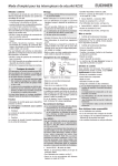
Actuator inserted locked unlocked locked Service and inspection Actuator removed open & 41 33 21 13 42 34 22 14 41 33 21 13 42 34 22 14 41 33 21 13 42 34 22 14 41 33 21 13 42 TX.A-... 34 22 14 41 33 21 11 42 34 22 12 41 33 21 11 42 34 22 12 41 33 21 11 42 34 22 12 41 33 21 11 42 TX.B-... 34 22 12 41 33 21 13 42 34 22 14 41 33 21 13 42 34 22 14 41 33 21 13 42 34 22 14 41 33 21 13 42 TX.C-... 34 22 14 Figure 2: Switching elements and switching functions 4. 3. 2. 1. 4. 3. 2. 1. 1 2 4 3 5 2 1 U B LED LED U S 0V GN RD Insertion depth s 134 GN TX3...024 TX4...024 Exclusion of liability under the following conditions: Leading with screen spring 12 1 18 17 10 13 2 19 16 9 14 3 15 4 8 7 5 6 1 GN 2 25,5 15 4 3 39 19 RD 7 41 42 8 13 33 34 14 9 21 22 10 11 11/13 12/14 5 PE/12 G 21,5 59 Figure 3a: TX...M G = M20x1.5 TX...N G = 1“ NPT 1 6 TX3...RC18 TX4...RC18 4,5 8,5 4 17 GN 2 15 Figure 3b: 5 3 16 22 TX...C18 19 RD 65 inserted 80 Figure 3c: TX...BH12 Approach speed, max. 20 m/min Switching principle Slow-action switching element Contact material Silver alloy, gold flashed Connection type on switching element Screw terminals Connection type on circuit board Cage-pull clamps Conductor cross-section Max. 1.5 mm2 Ui = 250 V Ui = 50 V 9 21 22 10 Utilization category for the switching element to IEC 947-5-1 11 11/13 12/14 5 AC-15 DC-13 4 A 230 V 4 A 24 V Switching voltage, min. 12 V Short circuit protection (control circuit fuse) 11 29 R 10 6 5 1 Duty cycle 100 % Operating frequency max. on TX3 and TX4 45 min-1 Control voltage US on TX3...024 / TX4...024 AC/DC 24 V Actuating force 35 N Extraction force 35 N Retention force 20 N Locking force Fmax 1700 N Locking force Fzh in accordance (F = Fmax) = 1300 N Zh with Test Principles GS-ET-19 1.3 3 2 GN 1 5 RD 4 A gG Solenoid operating voltage UB / AC/DC 24 V 8 W power input (TX3...024 and TX 4...024: AC/DC 110 V 10 W IB = 2 A for TIMP = 250 ms) AC/DC 230 V 11 W 12 7 3 3 Figure 4: Insertion depth and approach radii Any, actuating head down preferred 14 8 9 2 10 4 TX3...BH12 TX4...BH12 > 440 -20...+80°C Installation position 34 5 > 300 >1x10⁶ Ambient temperature 42 4 32 + 8 Mech. operating cycles 41 R 32 + 1 IP 67 IP 65 33 Figure 3: Dimension drawings Standard Degree of protection according to IEC 529 with cable gland with plug connector 13 60 inserted 75 1 Pin assignment Plug connector BH12 Overtravel Die-cast alloy, cathodically dipped Switching current, min., at 24 V 1 mA 58 Insertion depth s Approach radius R Value Housing material 7 ∅26 Actuator Parameters Rated insulation voltage with cable gland with plug connector Leading with screen spring R 8 PE/12 ∅26 if the unit is not used for its intended purpose non-compliance with safety regulations installation and electrical connection not performed by authorized personnel failure to perform functional checks. Technical data 6 16 Replacement of individual parts or assemblies is not permitted! Safety switches must be exchanged completely after 1 million switching operations. TX1/TX2 TX...110/230 11 Pin assignment Plug connector RC18 TX1...RC18 TX2...RC18 30 42 4 Figure 5: Circuit diagrams Locking screw 18,8 3 U B LED LED 0V GN RD Insertion depth for M5 > 45 mm ISO 1207 (DIN 84), ISO 4762 (DIN 912) Mechanical RD release 4. 3. 2. 1. If damage or wear is found, the complete switch and actuator assembly must be replaced. s 58,5 46 4,5 240 4. 3. 2. 1. No servicing is required, but regular inspection of the following is necessary to ensure trouble-free long-term operation: correct switching function secure mounting of components dirt and wear sealing of cable entry loose cable connections or plug connectors. 12 41 42 33 34 21 22 11/13 12/14 4 6 2 11 PE/9 Figure 6: Pin assignment EUCHNER GmbH + Co. KG Kohlhammerstraße 16 D-70771 Leinfelden-Echterdingen Tel. +49/711/75 97-0 Fax +49/711/75 33 16 www.euchner.de [email protected] Subject to technical modifications; no responsibility is accepted for the accuracy of this information. © EUCHNER GmbH + Co. KG 079777-03-10/06 Operating Instructions Safety Switch TX...