1
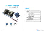
Operating Instructions
LEFT
FRON
LEFTT
RIGHT
FRONT
RIGHT
BACK
BACK
RIGHLE
T FT
POWER
VOL+
VOL-
CH-
MENU
SEL
7" COLOR LCD QUAD MONITOR
Please read this manual thoroughly before operating the unit,
and keep it for future reference.
V1.8
Contents
1. Precautions
2. Products
3. Monitor Installation
4. Connections
5. Parts Identification
6. Remote Operations
7. Menu Operations
8. Specifications
9. Troubleshooting
1
3
4
5
6
7
9
11
12
1. Precautions
Storage and Keeping
1. Do not expose the monitor to excessive heat or cold. The storage temperature of this device
is -30~+80℃, and the operating temperature is -20~+70 ℃. The humidity is Rh90%.
2. Never use this device where it is damp, such as close to wash basin, kitchen, swimming pool
and the like.
3. Never use this device in a dusty or smoky condition.
4. Avoid dropping or striking this device.
5. Avoid using this device in enclosed spaces, areas with excessive vibration or subject to
severe impacts.
6. Never puncture, scratch or use abrasive cleaning materials on this device.
7. Do not place cables where they may be pinched or stepped on.
8. Leave at least a 2" space between the monitor and walls, cabinets or other objects to allow
adequate air circulation around the unit.
Operating Precautions
1. The device may be powered by a 10~32 volt automotive battery.
2. Make sure all cables are connected properly. Observe polarity. Improper cable connections may
damage the monitor. Remove the power cable connections when you do not intend to use the unit.
3. Operate the unit according to the instruction.
! Warning!
1. High voltage is inside. The enclosure shall not be opened unless by professionals.
2. Do not watch the video while driving unless you are backing up the vehicle.
! Special Notice
-1-
Maintenance
1. Remove all the cable connections from the monitor before cleaning the unit.
2. Use a mild household detergent and clean the unit with a slightly damp,soft cloth.
Never use strong solvents such as thinner or benzine, as they might damage the finish
of the device.
CAUTION
RISK OF ELECTRIC SHOCK
DO NOT OPEN
CAUTION: TO REDUCE THE RISK OF ELECTRIC SHOCK,
DO NOT REMOVE COVER (OR BACK).
NO USER-SERVICEABLE PARTS INSIDE.
REFER SERVICING TO QUALIFIED SERVICE PERSONNEL.
This symbol is intended to alert the user to the presence of uninsulated "dangerous
voltage" within the product's enclosure that may be of sufficient magnitude to
constitute risk of electric shock to persons.
This symbol is intended to alert the user not to waste electrical and electronic
equipment.
CAUTION
You are cautioned that any changes or modifications not expressly approved in this manual could
void your warrantee and neccessitate expensive repairs.
Declaration of conformity
This device complies with Part 15 of the FCC Rules. Operation is
subject to the following two conditions:
(1) This device may not cause harmful interference.
(2) This device must accept any interference received, including
interference that may cause undesired operation.
E 13
- 2-
2. Products
U-Support Bracket
Center Mount Bracket
MUTE
POWE
R
UP
VOL
MENU
VOL
DN
MODE
LANG
AV and Power Supply
Conversion Cable
Sun Shield
SEL.
REST
P/N
AV
IR Remote Control
Front Panel AV Input Adapter
Angle Adjustment Screws
! Special Notice
Accessories may be different for different applications.
-3-
3. Monitor installation
3.1 Installation
③
3.1.1 Installation of sun shield
④
As illustrated, insert the hooks
① 、 ② 、 ③ 、 ④ of the sun
shield into the monitor.
②
①
①
3.1.2 Installation of U-support bracket
①As illustrated in the picture, align
the bracket with monitor.
②Adjust the bracket to proper angle
and tighten screws.
②
③
3.1.3 Installation of center mount bracket
①Loosen the knob on top of the center
mounting bracket in picture ④.
②Adjust monitor level by sliding the support to
the desired height.
③Adjust the angle of the monitor and tighten
the knob on the center mount bracket.
Knob
-4-
④
4. Connections
AV
VOL+
POWER
1 2
Camera 4
3
4 5
6
Camera 3
VOL-
MENU
CH-
SEL
8
7
9
10
11
Camera 2
12 13 14
Camera 1
1
AUX audio input
2
Green: Rec. V. output
3
Yellow:Live V. output
4
White: Audio output
5
White: Trigger 1
6
Blue: Trigger 2
7
Green: Trigger 3
8
Brown: Trigger 4
9
Yellow: Split trigger
10
13
Black: Ground
11
Red: Power
DVD audio input
(white RCA)
14
Null
(red RCA)
- 5-
12
DVD video input
(yellow RCA)
5. Parts Identification
1
AV
2
POWER
VOL+
VOL-
CH-
MENU
SEL
7
8
9
3
4 5
6
10
12
11
1
Color LCD screen
2
LDR
3
Remote signal receiver window
4
Power indicator
The green light/red light is on when monitor is powered/standby;
The light is off when the power is off.
5
Power off/on button
6
To increase / decrease the volume and switch between
values of each sub-menu
7
Menu selection and display mode (single, dual, triple, quadview, PIP image) selection
8
Menu control button
9
Jump key selector. Fast jump to the display mode specified
by SYSTEM SETUP - JUMP KEY
10
DVD A/V input
11
Loudspeaker
12
Installation port for center mount bracket
- 6-
6. Remote Operations
MUTE
POWER
1
2
4
6
3
UP
VOL
MENU
VOL
DN
5
7
9
8
MODE
SEL.
P/N
10
11
LANG
REST
AV
13
12
! WARNING
1. Please align the remote control with the remote signal receiver window to operate.
2. Never disassemble the remote control or allow it to drop, or get wet.
- 7-
1
MUTE
To mute / unmute the volume
2
POWER
Power off/on button
3
MENU
Menu control button
4
UP
Menu selection up
5
DN
Menu selection and display mode (single, dual, triple, quad-view,
PIP image) selection
6
VOLTo decrease the volume and switch between values of each sub-menu
7
VOL+
To increase the volume and switch between values of each sub-menu
8
MODE
Menu selection and display mode (single, dual, triple, quad-view,
PIP image) selection
9
SEL.
Jump key selector. Fast jump to the display mode specified
by SYSTEM SETUP - JUMP KEY
10
P/N
PAL/NTSC TV system selector
11
LANG
Language selection
12
REST
To restore factory settings
13
AV
To go to / leave DVD channel
- 8-
7. Menu Operations
7.1 OSD Setting
MAIN MENU
MAIN MENU
MENU
CAMERA
CAMERA
OSD
SYSTEM
TRIGGER
TRIGGER
SPLIT
RESET
SETUP
NAME
SETUP
SETUP
SETUP
PRIORITY
SETUP
ALL
SEL
SCALE:
To turn on / off electronic distance label. When set as ON,
electronic distance label will be displayed when rear view
camera (camera 3) is activated.
CAMERA
CAMERA
OSD
SYSTEM
TRIGGER
TRIGGER
SPLIT
RESET
SETUP
NAME
SETUP
SETUP
SETUP
PRIORITY
SETUP
ALL
VOL+
INPUT SCAN:
To turn on / off auto identification of camera inputs.
When INPUT SCAN is set as ON, monitor will display
connected cameras and skip inputs not in connection.
/
OSD
VOLSETUP
SCALE
ON
INPUT SCAN
OFF
BOUNDARY
WHITE
LANGUAGE
ENGLISH
V11:A00A20130909 (to be updated)
BOUNDARY:
To set color of the separation line between camera inputs.
White, gray, black and uncolored are available.
LANGUAGE:
To set OSD language. English, French, Dutch, Spanish,
German and Italian are available.
SOFTWARE VERSION:
To be updated at all times.
7.2 Trigger Setting
MAIN MENU
MAIN MENU
MENU
CAMERA
CAMERA
OSD
SYSTEM
TRIGGER
TRIGGER
SPLIT
RESET
SETUP
NAME
SETUP
SETUP
SETUP
PRIORITY
SETUP
ALL
SEL
TURN IMAGE:
To set the camera input(s) to be displayed when left-side camera
(camera 1) / right-side camera (camera 2) is activated.When set
as SINGLE, correspond camera input will be displayed when either
camera is activated.When set as SPLIT,split image of left-side and
rear view camera will be displayed when left-side camera is
activated; split image of right-side and rear view camera will be
displayed when right-side camera is activated.
REAR IMAGE:
To set the camera input(s) to be displayed when rear view camera
is activated. When set as BACK, the rear view camera will be
displayed when activated. When set as TRIPLE,left-side,
right-side and rear view camera will be displayed.
TRIGGER DELAY:
To set the delaying time of video display when trigger
signal goes off. Delaying time frame: 0-30 seconds.
CAMERA
CAMERA
OSD
SYSTEM
TRIGGER
TRIGGER
SPLIT
RESET
VOL+
SETUP
NAME
SETUP
SETUP
SETUP
PRIORITY
SETUP
ALL
/
VOL-
TRIGGER
SETUP
TURN IMAGE
REAR IMAGE
TRIGGER DELAY
SPLIT SCREEN:
LEFT
RIGHT
AUDIO
SINGLE
BACK
03 SEC
LEFT
RIGHT
LEFT
SPLIT SCREEN:
To set the camera input(s) to be displayed when “split”trigger wire is activated.
LEFT / RIGHT is to set the camera input to be displayed on the left / right side of monitor screen.
AUDIO is to set the audio output from any of the four cameras.
-9-
7.3 Jump Key Setting
MAIN MENU
MAIN MENU
MENU
CAMERA
CAMERA
OSD
SYSTEM
TRIGGER
TRIGGER
SPLIT
RESET
SETUP
NAME
SETUP
SETUP
SETUP
PRIORITY
SETUP
ALL
SEL
CAMERA
CAMERA
OSD
SYSTEM
TRIGGER
TRIGGER
SPLIT
RESET
SETUP
NAME
SETUP
SETUP
SETUP
PRIORITY
SETUP
ALL
VOL+
LEFT
TREFOIL
FRONT
Y-SPLIT
VOL-
SYSTEM SETUP
H-SPLIT
RIGHT
/
REC-V OUT
AUTOSCAN
SCAN DELAY
JUMP KEY
POWER ON
BEEP
SYSTEM
DIMMER
BACK
QUAD
OFF
01 SEC
LEFT
H-SPLIT
ON
NTSC
01
QUAD
DUAL
TRIPLE
PIP1
PIP2
PIP3
REC-V OUT:
To set the camera input(s) to be recorded when connected to DVR via the green RCA wire.
Left-side, right-side, front view, rear view camera and quad view image can be selected.
AUTOSCAN:
To set the auto scanning function. When AUTOSCAN is set as ON,
monitor will automatically switch between connected camera inputs and quad image.
SCAN DELAY:
To set the switching time of AUTOSCAN. Switching time frame: 0-60 seconds.
JUMP KEY:
To set the shortcut display mode from the 13 modes to the left.It can be activated by jump key selector.
P-ON MODE:
To set the default display model from the 13 modes to the left or STANDBY mode.
BEEP:
To turn on / off the warning tone. Default setting is ON and there will be a beeping sound when menu is being operated.
SYSTEM:
To set TV system: PAL / NTSC.
DIMMER:
To set backlighting brightness level of screen. Five levels and AUTO option are available; the higher the level,
the brighter. When set as AUTO, backlighting automatically adjusts in accordance with the outer brightness.
- 10-
8. Specifications
Dimension
7"
TV System
NTSC/PAL
Resolution
800 (W) × 3 (RGB) × 480 (H)
Brightness
400cd/㎡
Contrast
500:1
Viewing Angle
U: 50, D: 70, L: 70, R: 70
Aspect Ratio
16:9
Pixel Pitch (mm)
0.0642 (W) x 0.1790 (H)
Operating Temperature
-20 ℃ ~ +70 ℃
Storage Temperature
-30 ℃ ~ +80 ℃
Power Consumption
Max. 25W
Power Output to Camera
Max. 4 × 300mA, 12V
Power Supply
10V~32V
Video Input
4 video inputs for camera - peak value: 1Vp-p, impedance: 75 ohm
1 DVD input - peak value: 1Vp-p, impedance: 75 ohm
Audio Input
4 audio inputs for camera - peak value: 1Vp-p, impedance: 4.7K ohm
1 AUX audio input - peak value: 1Vp-p, impedance: 4.7K ohm
1 DVD audio input - peak value: 1Vp-p, impedance: 4.7K ohm
Video Ouput
1 REC Video output - peak value: 1Vp-p, impedance: 75 ohm
1 LIVE Video output - peak value: 1Vp-p, impedance: 75 ohm
Audio Output
1 REC audio output - peak value: 1Vp-p, impedance: 4.7K ohm
- 11-
9. Troubleshooting
The symptoms described below do not necessarily mean a failure within the
display. Please check the following items before you initiate request for repair.
Symptom
Possible Causes/Solutions
No picture, no sound
Improper connection of automobile adapter. Use of unauthorized power supply. Power switch is on OFF position.
No picture
Check whether AV cable is properly connected.
No sound
Check whether audio wire is properly connected or the sound
volume is turned off or set too low.
Dark picture
Check whether brightness and contrast are adjusted correctly;
Check whether the environmental temperature is too low.
No color
Adjust the color settings.
Upside down or lateral
inverted picture
Use the remote control horizontal /vertical selection switch to set
proper orientation
No reverse gear activated
screen(i.e. Picture)
The black wire of the monitor AV cable to the reversing light may
be loose. The red wire from the monitor may be loose.
- 12-
WARNING
Monitor systems are strictly intended to be installed as a supplement
and not intended for use as substitutes for rear-view mirror devices,
or for any other standard motor vehicle equipment required to be
installed on vehicles by law. Our products are no substitute for proper
defensive driving techniques, observance of traffic laws and motor
vehicle safety regulations.
Serial No:
Stock code:
-13-