1
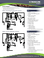
Electrical Diagram Semi-Automatic
Carmen S/1,2,3
230V
1
0
1
2
14
R
15
16
17
0
1
2
0
1
2
0
1
2
N
2
12
10
11
3
8
4
13
1
2
3
4
5
6
7
8
9
10
11
12
9
7
6
5
19
8
7
6
5
4
3
2
1
18
Key
6. Pump
7. Solenoid - valve 1st group
8. Solenoid - valve 2nd group
9. Solenoid - valve 3rd group
10. Solenoid - valve 4th group
1. Main Switch
2. Heating element thermal protector
3. Pressure switch
4. Heating element
5. Mains pilot lamp
1
0
1
2
0
1
2
0
1
2
0
1
2
14
R
15
S
T
N
2
8
4
6
5
13
12
10
11
3
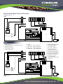
Carmen S/4
400V
17
16
11. Boiler filling pilot lamp
12. Automatic filling
solenoid valve
13. Hot water delivery
solenoid valve
14. Keyboard 1st group
15. Keyboard 2nd group
16. Keyboard 3rd group
17. Keyboard 4th group
18. Boiler level sensor
19. Control board
(e.g. Semi Automatic
4 group)
9
7
1
2
3
4
5
6
7
8
9
10
11
12
19
8
7
6
5
4
3
2
1
18
w w w . s t r e a m l i n e s u p p l i e s . c o m . a u 13