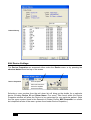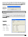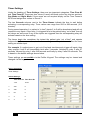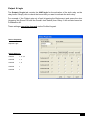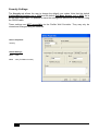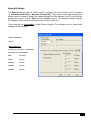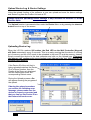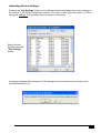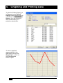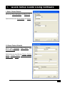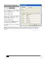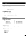
1
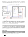
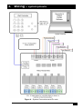
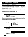
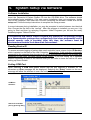
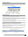
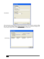
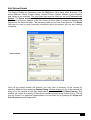
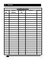
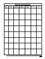
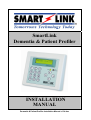
SmartLink
Dementia & Patient Profiler
INSTALLATION
MANUAL
Dementia & Patient Profiler Installation Manual v1.34.doc
Table of Contents
1.
Equipment List ________________________________________________________ 2
2.
Overview _____________________________________________________________ 3
Introduction____________________________________________________________ 3
Wall Controller Unit (DPC-01)____________________________________________ 3
Relay Module Box (DPR-01) _____________________________________________ 4
Software Requirements _________________________________________________ 5
Cable Requirements ____________________________________________________ 5
Power Supply __________________________________________________________ 5
3.
Wiring – system pinouts _________________________________________________ 6
4.
System Setup via Keypad ________________________________________________ 7
Patient Profiler Wall Controller (DPC-01) Commands ______________________ 7
Limited Access Menu (Default Pin Code = 1234) __________________________ 7
Full Access Menu (Default Pin Code = 4321) ______________________________ 7
Full Access Menu Descriptions __________________________________________ 8
5.
System Setup via Software _______________________________________________ 9
Software Installation ____________________________________________________ 9
Reading Device ID ______________________________________________________ 9
Setting COM Port _______________________________________________________ 9
Using Shortcut Buttons ________________________________________________ 10
Editing Room Details __________________________________________________ 10
Edit Patient Details ____________________________________________________ 12
Edit Device Settings ___________________________________________________ 13
Timer Names______________________________________________________________ 14
Timer Settings _____________________________________________________________ 15
Output 6 Logic_____________________________________________________________ 16
Security Settings ___________________________________________________________ 17
Special Settings ___________________________________________________________ 18
Upload Device Log & Device Settings ___________________________________ 19
Uploading Device Log ______________________________________________________ 19
Uploading Device Settings __________________________________________________ 20
6.
Graphing and Printing Data ____________________________________________ 21
7.
Quick Setup Guide Using Software _______________________________________ 22
I. Enter Room Details __________________________________________________ 22
II. Enter Patient Details_________________________________________________ 22
III. Enter Device Properties _____________________________________________ 23
8.
Appendix ____________________________________________________________ 24
Specifications _________________________________________________________ 24
Default Settings _______________________________________________________ 24
9.
1
Notes _______________________________________________________________ 25
Dementia & Patient Profiler Installation Manual v1.34.doc
1. Equipment List
The SmartLink Dementia & Patient Profiler package should contain the following:
•
Patient Profiler Wall Controller Unit (DPC-01)
•
Relay Module Box (DPR-01)
•
Demonstration Software Ver1.4 (DPS-01) (Full Version Purchased Separately)
•
5m RJ12-6Pin cable to connect wall controller to relay module
•
Installation Manual
Dementia & Patient Profiler Installation Manual v1.34.doc
2
2. Overview
Introduction
The SmartLink Dementia & Patient Profiler System provides a convenient method of
monitoring and logging patient activity. The system is comprised of three components: the
Wall Controller Unit (DPC-01), the Relay Module Box (DPR-01) and the Windows
Software Ver1.3 (DPS-01). Typically the Wall Controller unit provides a simple access point
where a patient’s activity may be reviewed and changes made to their profile. The term
“patient profile” is used to describe a patient’s “normal” activity. In the event that a patient
strays from the set profile, an alarm is raised, and the event is logged in memory. The ease
of use and simplicity of the Dementia & Patient Profiler make it an ideal system for
monitoring and controlling patient activity.
Wall Controller Unit (DPC-01)
The Wall Controller of the Dementia & Patient Profiler is primarily intended for use by the
Nursing Staff to view a patients log and also by System Administrators to review and alter a
patient’s profile. Depending on the user, certain functions of the Dementia & Patient Profiler
may or may not appear on the menu system (see Section 4 – “System Setup via
Keypad”).
Although a majority of the programming may be done from the keypad, there are certain
functions that can only be done using the Dementia & Patient Profiler Software such as
changing Timer Names and Access Pins. Other benefits of the software also include being
able to quickly upload device settings and patient logs (see section 5 – “System Setup via
Software”).
Figure 1 - Patient Profiler Wall Controller (DPC-01)
LCD
Data LED
Keypad
Active or Memory
Full LED (flashing)
Menu navigation
buttons
DB9 connector to
PC (during program)
RJ12 connector to Relay Module
3
Dementia & Patient Profiler Installation Manual v1.34.doc
Relay Module Box (DPR-01)
The Relay Module Box contains 5 optically isolated Inputs and 6 relay Outputs. By
default, the primary Input 1 is the Out of Bed sensor (normally closed) and is used logically
to enable each of the other Inputs (i.e. all other inputs are disabled until Input 1 is triggered).
All inputs have an individual relay output, which will operate after a programmed time has
expired unless the patient returns to bed. A sixth relay provides an additional output
capability that can be programmed as any logic combination of input 1 and inputs 2 to 5.
Figure 2 - Relay Module Box (DPR-01)
Power
(12V DC 1A)
Inputs
Optically
isolated
To Wall
Controller
Relay LED
indicators
Relay Outputs
Normally Open/
Normally Closed
Each of the 5 inputs are allocated a delay time expressed in seconds ranging from 0 to 999.
Provided the input is triggered within a valid Time Zone a corresponding output Relay will
trigger. If a Timer period overlaps a Time Zone (Day or Night mode), then on the change of
Time zone the timer is restarted at 0.
Each time an Input/Timer expires a LOG is generated with time & date stamp. If the
combinational logic is right for operation of output 6 then this is also recorded in the LOG.
An automatic reset will occur on all inputs if the Bed Input restores to normal regardless of
the Time Zone.
By default, the 5 inputs are labeled as shown:
•
•
•
•
•
Input 1 (Normally Closed)
Input 2 (Normally Open)
Input 3 (Normally Open)
Input 4 (Normally Open)
Input 5 (Normally Open)
– Bed Exit
– Room PIR
– Ensuite PIR
– Door Reed #1
– Door Reed #2
Dementia & Patient Profiler Installation Manual v1.34.doc
4
Relay Outputs 1 to 6 use low voltage N/O (Normally Open) and N/C (Normally Closed)
contacts rated at 24VDC 1Amp and if required to operate lighting, then a further relay or
contact can be used for the 240VAC lighting circuit.
Figure 3 – Example of a basic System Setup
Software Requirements
The Dementia & Patient Profiler Software (DPS-01) may operate on any IBM compatible PC
running Windows 2000 or Windows XP. Serial communication may be established using
Com Ports 1 to 8 via a standard DB9 serial cable. Device logs and settings may be
uploaded to the PC with the option to clear the device memory.
Cable Requirements
The Dementia and Patient Profiler System comes complete with a 5m connection cable
between the Wall Controller Unit (DPC-01) and the Relay Module Box (DPR-01).
However, if the need arises to increase the distance between the Wall Controller and the
Relay Module Box, the maximum distance of 15m should not be exceeded. Cable required
for extensions is RJ12-6 Pin in line.
Power Supply
The System will operate from either 12VDC un-regulated supply or a regulated 12VDC
power supply. If any external equipment such as a PIR is to be connected in parallel with
this power supply, it is recommended that a regulated power supply be used. Please ensure
that the current requirements are within the maximum specified.
5
Dementia & Patient Profiler Installation Manual v1.34.doc
3. Wiring – system pinouts
Figure 4 – System Connections and Pin-outs
Dementia & Patient Profiler Installation Manual v1.34.doc
6
4. System Setup via Keypad
Patient Profiler Wall Controller (DPC-01) Commands
The LCD display found on the Wall Controller Unit will normally display the current Date and
Time. During this period the unit will accept up to 2 PIN numbers. By entering either the
limited or full access PIN, the user may toggle through a menu system that corresponds to
the pin number. While in the menu system, unit will default back to requesting PIN again if
no key is pressed within 30 seconds.
Limited access enables a Nurse to view but not edit parameters. The Menus are described
in the following table:
Limited Access Menu (Default Pin Code = 1234)
0.
DISABLE / ENABLE INPUTS (RED LED INDICATES UNIT IS ACTIVE)
1.
View Log
2.
View Timers
3.
View I/O Logic
C.
Exit Menu (Press clr to Exit Menu)
The menu may be browsed using the up/down keys and selection made using the OK key.
Alternatively if the Item number is known then this provides a direct shortcut to the selection.
Full Access Menu (Default Pin Code = 4321)
0.
DISABLE / ENABLE INPUTS (RED LED INDICATES UNIT IS ACTIVE)
1.
View Log (on screen display of log of events)
2.
Timers
View Timers
2.
Edit Timers
3.
Edit Time Zones
4.
Load Defaults (See Appendix)
3.
View I/O Logic (for Relay Output 6 only)
4.
Set Time
5.
Set Date
6.
Test Outputs
7.
Test Inputs
8.
View Device ID
9.
Device Options
C.
7
1.
1.
Memory LED – on/off
2.
Beeper – on/off
3,
Input Polarity
Exit Menu (Press clr to Exit Menu)
Dementia & Patient Profiler Installation Manual v1.34.doc
Full Access Menu Descriptions
0.
Disables / Enables the Inputs
In the event of a patient being moved to theatre or another room or being
discharged.
1.
View Log
Enables the current log to be viewed without downloading information to the
computer (Windows Software).
2.
Timers
Edit Timers provides access to sub-menu where you can either view or edit
Timers and Time Zones. For convenience the DPC has the facility to edit the
timer values, as may be required with over regular alarms on a particular
patient.
3.
View I/O Logic
For Relay 6, Output is setup on the computer and transferred to the Wall
Controller unit (DPC-01) on initial setup. The actual logic condition however
can be viewed but not changed with this function.
4.& 5. Set Time and Date
Note that when device settings are transferred from a PC to the Wall Controller
Unit, the Computer Time and Date is also transferred.
6.
Test Outputs
The relay outputs may be individually tested with this function. An on board
LED indicates the status of each relay. Pressing #1 will toggle relay 1 on/off
with the status shown on the display. On pressing Clr all relays will turn off
again.
7.
Test Inputs
By activating the detector the status of the Input will be displayed.
8.
View Device ID
To View Wall Controller Unit ID (eg. SL-0904001).
9.
Device Options
To activate Memory LED On/Off, activate Beeper On/Off Options & Select
Input Polarity.
C.
Exit Menu
Press the clr key to Exit Menu.
Dementia & Patient Profiler Installation Manual v1.34.doc
8
5. System Setup via Software
Software Installation
Insert the Dementia & Patient Profiler CD into the CD-ROM drive. The software should
automatically begin installation. If for any reason installation does not commence, double
click on My Computer, then select the CD drive containing the software. Double click on the
setup.exe. Follow the setup instructions to complete the setup process.
In some instances during installation you may be prompted to select between two identical
files. Choose the file that is the “newest”. After the program is installed you may run it by
going to Start and then by selecting Programs. Under Programs you will see the newly
installed program “Patient Profiler”.
The Dementia and Patient Profiler Program will operate for 30 openings (Loads)
as a Demonstration package then automatically shut down permanently until a
special security code is provided. After this time, the software must be
purchased and enabled from SmartLink International.
Reading Device ID
To ensure accurate logging of patient data, each controller has a unique device ID Number,
which is printed on the back of the Wall Controller. Alternatively, if the controller is physically
connected to the computer then the device ID will be automatically read by the program and
displayed on the lower left hand corner of the screen. If you are setting up a database
without connection to each of the devices then you will need to know the device ID when
setting up Room Details.
Setting COM Port
When selecting a COM Port please ensure that the port selected is available for use
otherwise an Error message will be displayed. Selecting the “Retry” button on the error
message will allow the software to scan the next port for availability.
COM Port
Selection
Search for available
port by pressing Retry
9
Dementia & Patient Profiler Installation Manual v1.34.doc
Using Shortcut Buttons
Several shortcut buttons can be found on the top of the main menu. These icons initiate the
most commonly used features of the software such as Upload / Download, Clear Device
Memory, Patient Details, and Device Properties.
Shortcut buttons
Print
Upload
Clear Device Memory
Patient Details
Download
Device Properties
Editing Room Details
The Patient Profiler Windows Software (DPS-01) is capable of individually reading and
writing information to and from multiple Patient Profiler units (DPC-01).
The software identifies the different units from each other by using the unique Device ID
given to every Patient Profiler unit. Establishing a link between the Device ID and the room
number will be the starting point to setting up a system.
The Room Details are accessed under the Edit Menu. Four fields allow Room Number,
Room Name, Device ID, and Notes to be recorded.
The key fields which must be filled out are Room Number and Device ID. These two fields
are critical when setting up a new device as they determine which device goes with which
room.
The Room Name and Notes fields do not have to be filled out and are optional. However the
Notes field can be used to record installation date and any other changes that you make
throughout the history of the product.
Hint: If there is more than 1 patient per room, you may put a letter after the room number to
indicate that there is more than one Dementia & Patient Profiler Unit in that room.
Single Room Listing with Multiple Devices
Dementia & Patient Profiler Installation Manual v1.34.doc
10
Room Details
After entering the room details you may view a summary of the records by selecting View
and then selecting Room Listing. Double clicking on any of the records will bring up the
Room History window which summarises all the activity for that room.
Room History
11
Dementia & Patient Profiler Installation Manual v1.34.doc
Edit Patient Details
The Patient Details are accessed under the Edit Menu. Nine fields allow Surname, First
name, Address, Phone, Contact Name, Contact Phone, Contact Address, Room Number,
and Notes to be recorded. The key fields that must be filled out are the First and Last
Names. The Room Number field may be left as “none” or assigned to a Room if known.
The Name and Room Number fields are critical as they make a connection between the
Patient and the Room Number. The remaining fields do not have to be filled out. The Notes
field may be used to store important information about the patient such as any medical
conditions.
Patient Details
Once all the patient details are entered, you may view a summary of the records by
selecting View and then selecting Patient Listing. Double clicking on any of the records will
bring up a new window on the right hand side of the screen labeled Patient History. This
window will contain a summary of the patient’s details and also a log of their activity. The log
may be viewed in a graphical representation or be printed out by pressing the Graph and
Print Preview buttons respectively.
Dementia & Patient Profiler Installation Manual v1.34.doc
12
Patient History
Edit Device Settings
The Device Properties are accessed either under the Device menu or by pressing the
shortcut button found on top of the screen.
Device Properties
Selecting a room number from the pull down list will bring up the details for a particular
device including Device ID and Room Name. Five menu Tabs found within the Device
Properties window will allow the Device to be customized for any particular patient. (Note
that the menu system found in the Dementia & Patient Profiler Wall Controller is a similar
but simplified version of the menu system found under Device Properties.)
13
Dementia & Patient Profiler Installation Manual v1.34.doc
The Menu Tabs listed are Timer Names, Timer Settings, Output 6 logic, Security, and
Special. Once the settings are complete they may be saved and transfer to the device by
pressing the “Save” and “Send” buttons found on the bottom of the screen. Please note that
a warning message will be displayed if there is a mismatch in the Device ID. (Connection
to the Device with a DB9 serial cable is essential during the send procedure. )
Error Message
displayed when ID
Mismatch occurs
between Hardware
and Software.
The Default room number is configured with the Default settings. If required, these settings
may be changed and saved for later use.
Timer Names
You may change or add to the Timer Names and Descriptions. Once changes are made
you may save and send the information to the Profiler using the Send button. The changes
made on the software will be reflected in the Patient Profiler Wall Controller Unit. Note
that only the Timer Names are stored on the Profiler Unit and they cannot be changed. The
Timer Descriptions are not stored on the Profiler Unit and are provided only for the benefit of
the software user.
Device Properties:
Timer Names
Default Settings:
Timer Name
Timer Description
1. Bed
Bed Exit
2. Room
Room PIR
3. Ensuite
Ensuite PIR
4. Door#1
Door Reed #1
5. Door#2
Door Reed #2
Dementia & Patient Profiler Installation Manual v1.34.doc
14
Timer Settings
Under the heading of Timer Settings, there are two important categories: Time Zone #1
and Time Zone #2. These two time zones (if used) will break up the day into two sections,
Day Mode and Night Mode. If time zones are not required simply set the Time Zones to
00:00 and assign timer values to Zone #1.
The two Seconds columns next to the Timer Names indicate the time to wait before
activating a corresponding relay. Timer values can range from 000 to 999 seconds (16.5
minutes).
During normal operation (i.e. patient is “in bed”) inputs 2 to 5 will be deactivated and will not
respond to any inputs. Once relay 1 is triggered due to the patient being “out of bed” then all
the relays are active and if any of the inputs are triggered then the corresponding relay will
activate based on the time setting.
The timers begin the countdown the instant the patient gets “out of bed” and operate
independently from one another, i.e. the timer setting on one input does not effect the timer
setting on another input.
For example, if a patient were to get out of bed and simultaneously trigger all inputs, then
relay outputs 4 and 5 will immediately latch after 3 seconds, followed by relay 3 after 57
seconds, followed by relay 1 after 240 seconds and finally by relay 2 after 90 seconds. This
is based on the default settings shown below.
These settings are accessible via the Profiler Keypad. The settings may be viewed and
changed via the keypad.
Device Properties:
Timer Settings
Default Settings:
Time Zone #1: Time Zone #2:
7:30
19:30
1.
300
0
2.
390
0
3.
60
0
4.
3
0
5.
3
0
15
Dementia & Patient Profiler Installation Manual v1.34.doc
Output 6 Logic
The Output 6 Logic tab controls the AND logic for the activation of the sixth relay on the
relay board. Simply click to check the boxes that you want to activate the sixth relay.
For example, if the Patient gets out of bed (triggering the Bed sensor) and opens the door
(triggering the Room PIR and the Door#1 reed switch) then Relay 6 will activate based on
Combination #2.
These settings cannot be changed via the Profiler Keypad.
Device Properties:
Output 6 Logic
Default Settings:
Comb#1
1, 2, 3, 4
Comb#2
1, 4
Comb#3
1, 5
Comb#4
1
Comb#5
1
Dementia & Patient Profiler Installation Manual v1.34.doc
16
Security Settings
The Security tab allows the user to change the default user codes. Note that the default
Limited Menu Access code is 1234 and the default Full Menu Access code is 4321. As in
all the other menu tabs, it is possible to save the settings and send them to the device using
the RS232 cable.
These settings are NOT accessible via the Profiler Wall Controller. They may only be
viewed and changed using the software.
Device Properties:
Security
Default Settings:
Pin1
1234
Pin2
4321 (Full Menu Access)
17
Dementia & Patient Profiler Installation Manual v1.34.doc
Special Settings
The Special settings menu is mainly used to configure the Input Polarity of the 5 sensors,
i.e. Normally Open (N/O) or Normally Closed (N/C). There are also two other settings that
allows users to enable or disable the onboard beeper and the Memory full LED. Once all the
settings are correct, click on Save and then Send to device. The changes made using the
PC software will be instantly reflected in the Patient Profile unit.
These settings are accessible via the Profiler Keypad. The settings may be viewed and
changed via the keypad.
Device Properties:
Special
Default Settings:
Full Memory Led Flash – Unchecked
Disable Beeps - Unchecked
Bed
N/Closed
Room
N/Open
Ensuite
N/Open
Door#1
N/Open
Door#2
N/Open
Dementia & Patient Profiler Installation Manual v1.34.doc
18
Upload Device Log & Device Settings
Using the upload function of the software, a user can upload and save the device settings
and device Log from the Profiler Unit onto a PC.
Please note that uploading device settings is only available on Version 1.3 of the
Profiler Units.
The Upload function is accessed either under the Device Menu or by pressing the shortcut
button found on top of the screen.
Uploading Device Log
When the LOG file reaches 900 entries, the Red LED on the Wall Controller (Keypad)
will flash momentarily every 3 seconds. This is an early warning that the device is running
out of memory and the LOG needs to be uploaded to the host PC and the memory cleared.
Simply connect the device to the host computer and click on the Upload icon. If ignored,
the memory will continuously record events such that only the last 1000 records are
automatically retained.
If the Device ID of the unit that is
being uploaded matches the Device
ID of a Room Number, then the
Details of the Room are displayed
and the Data stored under the
corresponding Patient name.
During the Upload process a Bar
will appear showing the progress of
the upload.
If during the upload procedure
you receive the following error
message, please make sure the
device is properly connected and
that you can see the Device ID on
the bottom left hand corner.
19
Dementia & Patient Profiler Installation Manual v1.34.doc
Uploading Device Settings
Pressing the “Get Settings” button on the Upload window will display the current settings of
the device in the Device Properties window. The user is then given the option of either
saving the settings to an existing room or saving to a new room.
Saving Device
Settings using the
“Get Settings”
button.
A warning message will be displayed if the settings are to be saved into an existing room
with different Device ID.
Dementia & Patient Profiler Installation Manual v1.34.doc
20
6. Graphing and Printing Data
To view the Patient History, go
to View and select Patient
Listing. Simply double click on
a Patient to reveal the Patient
History. You can choose to
show all the history or a
particular upload date.
To view a graphical
representation of this
data simply click on the
Graph button or click on
the Print Preview
button to print.
21
Dementia & Patient Profiler Installation Manual v1.34.doc
7. Quick Setup Guide Using Software
I. Enter Room Details
Must enter Room Number and Device ID.
Optional items are: Room Name and Notes.
II. Enter Patient Details
Must enter Surname, First Name and
Room Number.
Optional items are Address, Phone, Contact
Name, Contact Phone, Contact Address,
Room Name, & Notes
Dementia & Patient Profiler Installation Manual v1.34.doc
22
III. Enter Device Properties
Select the Room Number from the
Pull down menu.
Fill in the details for Timer Names,
Timer Settings, Output 6 Logic,
Security, and Special.
Press on Save button.
Connect the Dementia and Patient
Profiler unit to the PC using a
standard DB9 serial cable.
Press the Send button.
The Profiler Unit will Beep to indicate
settings have been transferred.
See Page 14 to 18 for Default
settings.
Hint: An easy way to setup Device Properties is to send the Default device properties to a
Device and then upload the settings to a corresponding room using the “Get Settings”
feature.
23
Dementia & Patient Profiler Installation Manual v1.34.doc
8. Appendix
Specifications
•
Wall Controller Unit (DPC-01)
Size:
140 x 130 x 40mm
Connection: RJ12-6Pin to Relay Module Box
DB9 Pin (Female) to PC
•
Relay Module Box (DPR-01)
Size:
110 x 160 x 72mm
Power:
+12VDC 250mA max (relays on)
Relay:
Relays are rated at 24V DC, 1A Max
Default Settings
•
Default Timers in Seconds:
Zone 1).
1. 300
2. 390
3. 060
4. 003
5. 003
•
Default Time Zones:
Zone 1).
•
Bed Exit
Room PIR
Ensuite PIR
Door Reed #1
Door Reed #2
Zone 2).
0
(Note 0 disables the Input)
0
(Note 0 disables the Input)
0
(Note 0 disables the Input)
0
(Note 0 disables the Input)
0
(Note 0 disables the Input)
07:30
Zone 2).
19:30
Default IO Logic (Relay Output 6):
Combo 1.
Combo 2.
Combo 3.
Combo 4.
Combo 5.
1,2,3,4
1&4
1&5
1
1
Dementia & Patient Profiler Installation Manual v1.34.doc
24
9. Notes
Room
No.
25
ROOM DETAILS
Room
Device
Notes
Name
ID
Dementia & Patient Profiler Installation Manual v1.34.doc
Date
DEVICE PROPERTIES
Room
No.
Device
ID
Timer
Names
Timer
Settings
Output 6
Logic
Security
Dementia & Patient Profiler Installation Manual v1.34.doc
Special
26
© Copyright SmartLink International Pty Ltd
July 2008
Level 1, 304-308 New St, Brighton VIC 3186 Australia
Tel: +61 3 9596 0770 Fax: +61 3 9596 8195
Email: [email protected]
Web Site: www.smartlink.com.au
To the best of our knowledge, the information contained in this manual is correct at the time of print. SmartLink International Pty Ltd
reserve the right to make changes to the features and specifications at any time without prior notice in the course of product development.
27
Dementia & Patient Profiler Installation Manual v1.34.doc