1
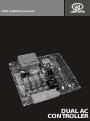
CP93 Installation manual
DUAL AC
CONTROLLER
Company Profile
Centurion Systems (Pty) Ltd, South Africa, has been manufacturing automatic gate systems since 1986,
and is committed to providing reliable, cost effective solutions in the field of gate and access
automation.
We offer a diverse range of products including gate motors, GSM-based products, garage door motors,
remote controls, keypads, traffic barriers, proximity access control and intercom systems.
Our products are developed by an in-house team of talented engineers that are constantly researching
new and innovative technologies to improve our existing products and expand our product range.
Our production facility in Johannesburg is ISO:9001 quality assurance certified, and all our products are
manufactured to the highest level of quality with a 100% test to specification.
Through a team of dedicated technicians and sales personnel, together with a fully fledged in-house
training facility, we are committed to providing unmatched service to our customers and support for our
products.
A worldwide network of distributors and installers ensure that our products remain The Automatic
Choice in access automation .
Further information is available on our website www.centsys.com.au
Centurion Systems (Pty) Ltd reserves the right to make changes to the products described in this document without notice and without
obligation of Centurion Systems (Pty) Ltd to notify any persons of any such revisions or changes. Additionally, Centurion Systems (Pty) Ltd
makes no representations or warranties with respect to this document.
No part of this document may be copied, stored in a retrieval system or transmitted in any form or by any means electronic, mechanical,
optical or photographic, without the express prior written consent of Centurion Systems (Pty) Ltd.
Table of Contents
Important Safety Instructions . . . . . . . . . . . . . . . . . . . . . . . . . . . . . . . . . . . . . . . . . . . . . . . . . . . . . . . . . 4
Fast Track . . . . . . . . . . . . . . . . . . . . . . . . . . . . . . . . . . . . . . . . . . . . . . . . . . . . . . . . . . . . . . . . . . . . . . . 5
General Description . . . . . . . . . . . . . . . . . . . . . . . . . . . . . . . . . . . . . . . . . . . . . . . . . . . . . . . . . . . . . . . . 7
Specifications . . . . . . . . . . . . . . . . . . . . . . . . . . . . . . . . . . . . . . . . . . . . . . . . . . . . . . . . . . . . . . . . . . 7
Product Identification . . . . . . . . . . . . . . . . . . . . . . . . . . . . . . . . . . . . . . . . . . . . . . . . . . . . . . . . . . . . . . . 9
Required Tools & Equipment . . . . . . . . . . . . . . . . . . . . . . . . . . . . . . . . . . . . . . . . . . . . . . . . . . . . . . . . 10
Site Considerations . . . . . . . . . . . . . . . . . . . . . . . . . . . . . . . . . . . . . . . . . . . . . . . . . . . . . . . . . . . . . . . . 11
Cabling Requirements. . . . . . . . . . . . . . . . . . . . . . . . . . . . . . . . . . . . . . . . . . . . . . . . . . . . . . . . . . . . . . 13
Controller Installation . . . . . . . . . . . . . . . . . . . . . . . . . . . . . . . . . . . . . . . . . . . . . . . . . . . . . . . . . . . . . . 14
Electrical Setup . . . . . . . . . . . . . . . . . . . . . . . . . . . . . . . . . . . . . . . . . . . . . . . . . . . . . . . . . . . . . . . . . . . 15
Connections Terminal Functions & Descriptions . . . . . . . . . . . . . . . . . . . . . . . . . . . . . . . . . . . . . . 15
Terminal Identification and numbering . . . . . . . . . . . . . . . . . . . . . . . . . . . . . . . . . . . . . . . . . . . . . . 16
Motor and Limit Switch Connections . . . . . . . . . . . . . . . . . . . . . . . . . . . . . . . . . . . . . . . . . . . . . . . 18
Radio and Intercom Connections. . . . . . . . . . . . . . . . . . . . . . . . . . . . . . . . . . . . . . . . . . . . . . . . . . 19
Solenoid/Magnetic Lock . . . . . . . . . . . . . . . . . . . . . . . . . . . . . . . . . . . . . . . . . . . . . . . . . . . . . . . . . 20
Infrared Beams . . . . . . . . . . . . . . . . . . . . . . . . . . . . . . . . . . . . . . . . . . . . . . . . . . . . . . . . . . . . . . . . 22
Pedestrian Keyswitch and free-exit Loop . . . . . . . . . . . . . . . . . . . . . . . . . . . . . . . . . . . . . . . . . . . . 23
Status Led and Pillar/Courtesy Lamp(s). . . . . . . . . . . . . . . . . . . . . . . . . . . . . . . . . . . . . . . . . . . . . 24
Pillar Light Control and Emergency Stop Button (Optional) . . . . . . . . . . . . . . . . . . . . . . . . . . . . . 25
Beam 1 Input Configuration for Centrifugal Contact Motors . . . . . . . . . . . . . . . . . . . . . . . . . . . . . 26
Programming. . . . . . . . . . . . . . . . . . . . . . . . . . . . . . . . . . . . . . . . . . . . . . . . . . . . . . . . . . . . . . . . . . . . . 27
Orientation in the CP93 Programming Interface . . . . . . . . . . . . . . . . . . . . . . . . . . . . . . . . . . . . . . 27
Basic Programming Menu Navigation . . . . . . . . . . . . . . . . . . . . . . . . . . . . . . . . . . . . . . . . . . . . . . 27
Programmable Options of the CP93 . . . . . . . . . . . . . . . . . . . . . . . . . . . . . . . . . . . . . . . . . . . . . . . 30
Programming Each Menu Item. . . . . . . . . . . . . . . . . . . . . . . . . . . . . . . . . . . . . . . . . . . . . . . . . . . . 33
Programming Notes . . . . . . . . . . . . . . . . . . . . . . . . . . . . . . . . . . . . . . . . . . . . . . . . . . . . . . . . . . . . 55
Appendix . . . . . . . . . . . . . . . . . . . . . . . . . . . . . . . . . . . . . . . . . . . . . . . . . . . . . . . . . . . . . . . . . . . . . . 61
Appendix A . . . . . . . . . . . . . . . . . . . . . . . . . . . . . . . . . . . . . . . . . . . . . . . . . . . . . . . . . . . . . . . . . . . 61
Appendix B . . . . . . . . . . . . . . . . . . . . . . . . . . . . . . . . . . . . . . . . . . . . . . . . . . . . . . . . . . . . . . . . . . . 62
Appendix C . . . . . . . . . . . . . . . . . . . . . . . . . . . . . . . . . . . . . . . . . . . . . . . . . . . . . . . . . . . . . . . . . . . 63
Page 3
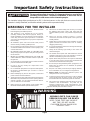
Important Safety Instructions
ATTENTION
To ensure the safety of people, it is important that you read all the
following instructions. Incorrect installation or incorrect use of
the product could cause serious harm to people.
The installer, being either professional or DIY, is the last person on the site that can ensure that the
operator is safely installed, and that the whole system can be operated safely.
WARNINGS FOR THE INSTALLER
1.
CAREFULLY READ AND FOLLOW ALL INSTRUCTIONS
before beginning to install the product.
2.
This appliance is not intended for use by persons
(including children) with reduced physical, sensory or
mental capabilities, or lack of experience and knowledge,
unless they have been given supervision or instruction
concerning use of the appliance* by a person responsible
for their safety.
3.
All installation, repair, and service work to this product
must be done by a suitably qualified person.
4.
Do not activate your gate opener unless you can see it and
can determine that its area of travel is clear of people, pets,
or other obstructions.
5.
NO ONE MAY CROSS THE PATH OF A MOVING GATE.
Always keep people and objects away from the gate and
its area of travel.
6.
NEVER LET CHILDREN OPERATE OR PLAY WITH THE
GATE CONTROLS, and do not allow children or pets near
the gate area.
7.
Secure all easily accessed gate opener controls in order to
prevent unauthorized use of the gate.
8.
Do not in any way modify the components of the
automated system.
9.
Do not install the equipment in an explosive atmosphere:
the presence of inflammable gas or fumes is a serious
danger to safety.
10. Before attempting any work on the system, cut electrical
power and disconnect the batteries.
11. The mains power supply of the automated system must be
fitted with an all-pole switch with contact opening distance
of 3mm or greater. Use of a 5A thermal breaker with allpole circuit break is recommended.
12. Make sure that an earth leakage circuit breaker with a
threshold of 30mA is fitted upstream of the system.
13. Never short circuit the battery and do not try to recharge
the batteries with power supply units other than that
supplied with the product, or by Centurion Systems (Pty)
Ltd.
14. Make sure that the earthing system is correctly
constructed, and that all metal parts of the system are
suitably earthed.
15. Safety devices must be fitted to the installation to guard
against mechanical movement risks such as crushing,
dragging and shearing.
16. It is recommended that at least one warning indicator light
be fitted to every system.
17. Always fit the warning signs visibly to the inside and
outside of the gate.
18. The installer must explain and demonstrate the manual
operation of the gate in case of an emergency, and must
hand the User/Warnings guide over to the user.
19. Explain these safety instructions to all persons authorized
to use this gate, and be sure that they understand the
hazards associated with automated gates.
20. Do not leave packing materials (plastic, polystyrene, etc.)
within reach of children as such materials are potential
sources of danger.
21. Dispose of all waste products like packaging materials,
worn out batteries, etc, according to local regulations.
22. Always check the obstruction detection system, and
safety devices for correct operation.
23. Centurion Systems (Pty) Ltd does not accept any liability
caused by improper use of the product, or for use other
than that for which the automated system was intended.
24. This product was designed and built strictly for the use
indicated in this documentation. Any other use, not
expressly indicated here, could compromise the good
condition/operation of the product and/or be a source of
* Appliance should be product described in manual
WARNING
MOVING GATE CAN CAUSE
SERIOUS INJURY OR DEATH
KEEP CLEAR. GATE MAY MOVE AT
ANY TIME. DO NOT ALLOW
CHILDREN TO PLAY IN AREA OR
OPERATE GATE .
Page 4
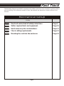
Fast Track
The following steps are provided for experienced installers and serve as a checklist to get the product
up and running in the minimum amount of time. More details are referred to in later sections in the
manual.
Mechanical Setup
Action
Step 1
Read and understand all safety instructions
Page 4
Step 2
Gather required tools and equipment.
Page 10
Step 3
Heed necessary site considerations.
Page 11
Step 4
Check cabling requirements.
Page 13
Step 5
Mounting the card into the enclosure
Page 14
Page 5
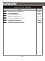
Fast Track
The following steps are provided for experienced installers and serve as a checklist to get the product
up and running in the minimum amount of time. More details are referred to in later sections in the
Electrical Setup
Action
Step 5
Making Electrical Connections.
Page 15
Step 6
Initial Programming.
Page 26
Step 7
Configuring limit Switches.
Page 33
Step 8
Configuring Safety Devices.
Page 41
Step 9
Programming Mode of Operation.
Page 36
Step 10
Configuring the leaf order.
Page 45
Step 11
Programming operator run times.
Page 48
Page 6
General Description
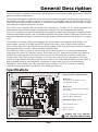
The CP93 Dual AC controller is a controller card designed to control a pair of gates driven by AC induction
motors in various configurations.
The product is designed to allow full control of a set of double swing gates that interleave, irrespective of
the operator, and with, or without the use of limit switches. Parameters such as the leaf delay, and leaf
order are fully programmable in addition to numerous other standard features such as the run time,
reversal delay and general Mode of Operation.
The CP93 comes complete with an Installer User Interface (or “Installer UI”, for short) that allows full
customization of the various programming features, easily and in a very straightforward manner.
This is the key feature of the product that allows the installer to rapidly make changes to operating modes
and various parameters of the card, in the field and without using other extensive methods. Thanks to this
extensive programming feature, the product may be used as a replacement for other brands of controller
card.
The installer UI consists of three push buttons and a three-digit, seven segment LED display. The
three buttons, namely UP, DOWN and ENTER allow full access to over 23 menu items and submenus. Each menu item corresponds to a particular setting of the card, which may easily be selected
and adjusted within seconds, saving valuable installation time.
The product provides a means to resolve relay contact arcing, which is a common problem when
using relays to control AC induction motors. Each relay has a PF setting which allows the installer to
optimize the switching time of the relay such that the card will endeavour to make or break relay
contacts when the motor current is tending, or close to zero. In this way it is possible to “tune out”
contact arcing problems and allows the use of any kind of AC motor without detriment to the CP93. A
factory default setting is provided which is sufficient in most cases, but, for those demanding
installations, these settings are fully adjustable by the installer. The CP93 occupies a relatively
compact footprint and easily retrofits into most existing enclosures.
Specifications
166mm
Mounting Hole Standardization
Q8
R55
R56
CP93 V1.1 DUAL AC CONTROLLER
R57
T1
A
B
A
Q9
R63
R62
B
R61
Q10
R59
DSP1
ZD7
R21 R20
RL4
F3
R18 R17
R41
C15
R44
C16
R45
C17
R49
C18
Q7
A
N
E
R
COM
F
R
COM
RL6
LIGHT
SOLENOID
D11 R46
GA1
R9
R8
R13
R7
ZD3
C5
C4
LD4
LD3
LD5
R16
ZD5
R15 R14
R6
R5
ZD2
A
GA2
PL1
A B
A
B
LIGHT SOLENOID
N.O. CON
N
E R COM F R COM F
AC MAINS MASTER MTR SLAVE MTR
N.C. CON
PB1
L
B
F
JP2
L
JP1
AC MAINS MASTER MTR SLAVE MTR
USE DESIGNATED
FUSES ONLY
C8
C7
PL2
F2
Q4
R40
K1
R10
ZD6
R64
D8
SERIAL NUMBER LABEL
R51
LD6
ZD4
R11
C6
RL5
R19
LD12
R22
C9
R12
5 AMP
F/B
ZD9
R25
LD7
R54
C10
R27 R26
GA3
Q6
D10
RL3
R23
Q1
R24
ZD11
R28
LD9
U1
R32
R30 R29
C11
LD13 LD10 LD11
D9
RL2
R31
LD8
D7
RL1
R47
Q5
C12
R33
ZD8
LD2
C3
VR1
ZD11
ENTER
STATUS
K2
R34
C13
C2
D6
R48
Q3
DOWN
R37
ZD12
R35
R36
Y1
R42
Q2
PB4
R58
LD1
MAINS ON
R43
PB3
C20
R2
C14
R4
F1
1 AMP
F/B
C1
145mm
UP
C19
R53
DB1
PB2
ZD13
R39 R38
D14
D13
R52
R1
*WARNING*
ISOLATE MAINS BEFORE
WORKING ON CARD
5 AMP
F/B
D12
ZD1
R3
D5
MV1
MV3
TRG COM PED BM1 BM2 COM FRX COM STP LED LIT MLO COM MLC SLO COM SLC 12V COM
R60
MV2
TEST
R68
R65
R69
R66
R67
Figure 1 Overall Dimensions
Page 7
Hole Set A 112.5mm x 103.5mm between
04.5mm hole centres.
Hole Set B
156.5mm x 135mm between 04mm
hole centres.
For new installations, please use
Hole Set B for mounting.
Maximum height: 43mm
Hole Diameters are:
A-Set= 4.5mm
B-Set= 4 mm
B
ALWAYS USE THE CORRECT
SIZE STANDOFF AND FASTENER.
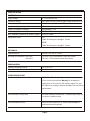
SPECIFICATION
ELECTRICAL
Supply Voltage
AC 230V 50/60Hz 10%
Switching Capacity
Max. 5AMP per relay contact at rated voltage and power factor.
Auxillary Relay (Solenoid and
10 AMP max with a 24-volt AC/DC solenoid
Lamp) switching capacity
100 watts max. Lamp wattage at 230V AC
Power Consumption in Standby
Approximately 5.5 VA
Auxillary Supply Output Voltage
12-15,2 V DC (max.) unregulated
Max. Allowable current draw on Auxillary Supply
300mA (0,3 AMP)
Replacement Fuses
F1 1 AMP Fast blow glass cartridge 5 x 20mm
F2, F3 5 AMP Fast blow glass cartridge 5 x 20mm
MECHANICAL
Card Dimensions
166 mm x 145 mm ± 0.4 mm
Mounting Hole Diameters- Hole Set A:
112.5mm x 103.5mm between 4.5mm hole centres
Hole Set B:
136.5mm x 135mm between 4mm hole centres
ENVIRONMENTAL
Operating Temperature Range
-50 °C to +55°C
Relative Humidity (RH) non-condensing
20 - 80 %
OTHER SPECIFICATIONS
Recommended Electric (solenoid) lock
12-24V AC or DC solenoid lock powered from a separate power
source such as a transformer. Warning: Do not attempt to
supply power to lock from the 12V auxillary supply! The card
will malfunction resulting in possible damage to the card and the
gate operators.
Recommended Courtesy lamp
100 watts maximum incandescent. To operate larger lamps use
a contactor or additional relay.
Recommended Enclosure
Plastic enclosure rated to IP 56. Internal metal baseplate is
preferred and must be earthed.
Page 8
Product Identification
Q8
R55
R56
CP93 V1.1 DUAL AC CONTROLLER
R57
T1
A
B
A
Q9
R63
R62
7
DSP1
R59
R24
C10
R27 R26
D10
ZD7
R21 R20
RL4
F3
R11
C6
RL5
R18 R17
F2
Q4
R40
R41
C15
R44
C16
R45
C17
R49
C18
Q7
A
N
E
R
COM
F
R
COM
F
RL6
LIGHT
SOLENOID
GA1
R9
R8
R7
ZD3
C5
C4
R13
R6
R5
ZD2
LD4
LD3
2
A
GA2
PL1
N
E
A B
A
B
LIGHT SOLENOID
N.O. CON
R COM F R COM F
AC MAINS MASTER MTR SLAVE MTR
L
N.C. CON
PB1
1
B
D11 R46
JP2
L
JP1
AC MAINS MASTER MTR SLAVE MTR
USE DESIGNATED
FUSES ONLY
ZD5
R15 R14
PL2
5
C8
C7
R10
ZD6
R16
R64
D8
SERIAL NUMBER LABEL
R51
K1
R19
ZD4
C9
R12
5 AMP
F/B
ZD9
R22
Y1
Q6
R28
R25
GA3
LD5
R54
R30 R29
C11
LD12
U1
R23
Q1
LD9
R58
ZD11
LD6
LD2
10
R32
LD7
STATUS
K2
R31
R33
ZD8
LD13 LD10 LD11
D9
RL3
ENTER
LD8
D7
RL2
R47
Q5
DOWN
R34
ZD11
C13
C2
D6
RL1
9
R48
Q3
ZD12
R35
R36
C20
5
R42
PB4
R37
R4
VR1
MAINS ON
Q2
C19
R53
LD1
C3
1 AMP
F/B
R43
PB3
UP
F1
C1
R2
C14
C12
4
DB1
PB2
ZD13
R39 R38
D14
D13
R52
R1
*WARNING*
ISOLATE MAINS BEFORE
WORKING ON CARD
ZD1
R3
D5
MV1
MV3
5 AMP
F/B
D12
TEST
6
R68
R65
R69
3
R66
R67
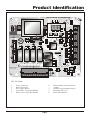
KEY TO ITEMS
Power Connector
Signal Connector
Test Trigger Button
System Fuse 1A QUICK BLOW
Motor Fuses 5A QUICK BLOW
6.
7.
8
9.
Figure 2 Product Identification
Page 9
Solenoid Relay Contact Selector
Jumper
Installer Programming Interface
Mounting Hole (8 x)
Mains ON Indicator
B
TRG COM PED BM1 BM2 COM FRX COM STP LED LIT MLO COM MLC SLO COM SLC 12V COM
R60
MV2
1.
2.
3.
4.
5.
8
B
R61
Q10
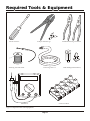
Required Tools & Equipment
Flat Screwdriver
Crimper and Pin Lugs
Soldering Iron and Solder
Connecting Wire 0.3
Standard and Long Nose Pliers
PCB Standoff (Metal/Plastic)
Connector Block
Mlultimeter
Figure 3 Required Tools and Equipment
Page 10
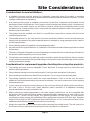
Site Considerations
Considerations for new installations:
1. A suitable enclosure must be chosen for installation, especially where the product is mounted
outside. This enclosure must be IP56 rated to prevent moisture problems and shock hazards. The use
of proper cable glands is mandatory.
2. If an existing mains supply is available, ensure that it is fed from a separate circuit breaker on the
distribution board of the premises. Don't forget to install a double pole isolator switch if one does not
exist. If there is no mains supply, you will have to install a cable from the distribution board to the
installation point. Please be very sure to comply with the relevant installation rules in this regard. If in
doubt consult an electrician.
3. The product must be installed such that it is very difficult or impossible to tamper with it from the
outside of the premises.
4. The installed product i.e. the card and it's enclosure should be installed in a manner that it does not
obstruct the movement of the gates especially when for example, a swing gate approaches a wall in
the fully open position.
5. Ensure that the product is suitable for the intended application.
6. Key switches for the special features i.e. Pedestrian, should be mounted inside as opposed to outside
the premises.
7. The mass and length of the gate you intend operating should be within the combined specifications of
this product and the operator you choose to install.
8. The operators you intend using with this product should be within the specification of this controller.
Using operators that exceed the specified ratings of this product may cause damage to this product
and be a potential fire hazard.
Considerations for replacement/upgrade of existing sites using other products:
1. The existing enclosure must be adequate. Check that there is enough space to mount this card
without causing problems.
2. Ensure that the existing enclosure seals properly. Check the seals and replace if necessary.
3. Has a double-pole isolator been fitted? If not, install one. This is a very necessary safety item.
4. The existing operators must be within the card's specifications. If this is not the case the use of
additional control equipment may be necessary for example, the use of contactors to control existing
three phase motors.
5. In most cases, the original mounting bosses in the enclosure will line up with the holes provided on
this card. If this is not the case, install adhesive plastic standoffs or fit additional mounting
bosses/standoffs to securely mount the card.
6. Make sure that any existing equipment i.e. the radio, beams, solenoid lock, etc are compatible with
this product. Many systems by other vendors operate all ancillary equipment (i.e. radio, beams, loop
detectors, etc…) from a 24 volt supply. This product provides a 12 volt supply. You may have to
reconfigure or replace some of the existing ancillary equipment to operate at 12 volts. Also, be aware
that the 12 volt supply is NOT sufficient to drive solenoid locks. In such a case you will have to fit an
additional transformer to operate the solenoid lock exclusively.
7. Always document the existing connections before removing the existing board. This will save you a
lot of time should you need to put everything back the way it was for some reason.
Page 11
Site Considerations
8. You may have to extend the internal wiring inside the box. This is often the case when replacing the
existing board with a different product. Use terminal block (“chockblock”) and lengths of wire to do
this. Ensure that the wire you use is sufficient to carry the rated currents.
9. Ensure that there is an EARTH connection inside the box and ensure that the card is connected to this
EARTH. Lightning protection is rendered ineffective if this rule is not observed.
10. Check the courtesy light, if present. Be careful that the wattage of this lamp does not exceed the
switching current rating of the relay on this card.
11. Check the condition and suitability of the wiring at the existing site. The use of two-core norse cable,
where the earth conductor is used as a neutral, leaving the motors un-earthed is not acceptable for
use with this product. Replace the cable with a 4-core type if this is the case.
Page 12
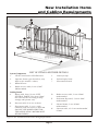
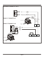
New Installation Items
and Cabling Requirements
5
7
4
3
D
E
2
1
A
G
B
2
C
6
F
6
LIST OF ITEMS AND THEIR DETAILS
System Components
1.
CP 93 Control unit in IP56 Enclosure
5.
Courtesy Lamp
2.
Operator (Linear type shown here, may
differ as per installer’s choice)
6.
Infrared safety beam
7.
Intercom Gooseneck
3.
Radio Receiver
4.
Radio receiver cable (3 core 0,5mm2
Multistranded).
D.
Radio receiver cable; 3 core 0.5mm²
multistranded
E.
Pedestrian Keyswitch; 2 core 0.5mm²
multistranded
F.
Infrared beams; 3 core 0.5mm²
multistranded
G.
Intercom cable; n2+2 core multistranded
0.5mm²
Cabling Details
A.
Mains cable, three (3) core; LIVE,
NEUTRAL, EARTH. Core area 8.5mm²
min. (increase this according to lamp
wattage and operator size).
B.
Intercom cable n1+6 core to house
C.
Slave motor cable, 3- core + earth
conductor with core area of 3.5mm² min.
(DO NOT USE NORSE CABLE FOR
THIS APPLICATION- MOTORS MUST
BE GROUNDED)
Figure 4 New Installation Items and Cabling Requirements
Page 13
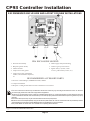
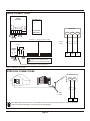
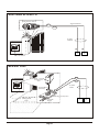
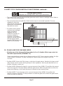
CP93 Controller Installation
RECOMMENDED ENCLOSURE AND LAYOUT FOR NEW INSTALLATIONS
IP56 ENCLOSURE LEGEND
1. Enclosure bottom half
6. Mains supply cable from dwelling
2. Baseplate (plastic/metal)
7. Cables to gate operator motors
3. CP93 Controller
8. Signal cable(s): (beams, radio
receiver, pedestrian keyswitch, etc.)
4. Compression cable gland
5. Compression cable gland mains
isolator, solenoid lock transformer,
etc.
RECOMMENDED ACCESSORY PARTS
1. Enclosure- CENTSYS Type, GEWISS GW 44 207, SAREL
2. Compression Glands
3. Baseplate- 1.2mm galvanised sheet metal cut and bent to suit enclosure.
! The colour codes shown here are only for illustration. Actual colour codes may vary according to the actual motor wires, etc. However
the mains supply cable colour code must comply with local regulations.
!Mount the box on a flat surface such as a wall. Use suitable fastening devices i.e. screws and rawl plugs. In cases where the enclosure
is to be embedded into the wall, make sure that the top cover mates properly with the base and that the compression glands are properly
fastened.
!The isolator switch (not shown) may be mounted inside the enclosure if space permits.
!Mount the card to the baseplate (if fitted) using recommended plastic stand-offs. The use of metal stand-offs are permitted provided a
metal baseplate is present and is earthed. Metal standoff's overall diameter may not exceed 6mm.
!This product MUST be earthed even if it is installed in a completely plastic enclosure.
Figure 5 CP93 Recommended Enclosure
Page 14
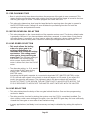
CP93 Electrical Set-up
SOLENOID
B
A
B
LIGHT SOLENOID
Power Terminals
JP2
LIGHT
BM2 -Standard safety beam input (closing
beam)
R = REVERSE Reverse winding of motor
COM = COMMON Motor winding common
(neutral)
F = FORWARD Forward winding of motor
LIT -Light Control button input signal
MLO -Master Gate Open Limit Switch
5. Solenoid
Selectable N.O. or N.C. potential-free relay
contact. Contact type can be selected as
needed by changing the jumper on the card
as shown: Max. Current capacity of
SOLENOID relay contact is 1 AMP @ 24VDC
BM1 -Opening beam input / motor error signal*
Pushbutton
LED -Status LED output
Potential-free relay contact for controlling a
courtesy lamp. Normally-open contact.
PED -Pedestrian mode activation signal.
FRX -Free-exit signal input from FREE-EXIT
STP -Emergency Stop input
4. Light
TRG -Trigger input signal from radio receiver.
JP2
Figure 7 Normally-closed (N.C.)
3. Slave Motor
Signal Terminals and Names
GA1
N.O. CON
B
A
B
LIGHT SOLENOID
N.C. CON
JP1
1. AC Mains
Figure 6 Normally-open (N.O.)
L = LIVE Live conductor of AC mains supply
N =NEUTRAL Neutral conductor of AC
LIGHT
SOLENOID
mains supply
E = EARTH Earth conductor of AC mains
supply and building
2. Master Motor
R = REVERSE Reverse winding of motor
COM = COMMON Motor winding common
(neutral)
F = FORWARD Forward winding of motor
GA1
N.O. CON
CP93 Connections
Terminal Functions &
Descriptions
JP1
HAZARDOUS VOLTAGES.
REMOVE POWER WHEN
MAKING CONNECTIONS
The following pages describe details of the electrical connections that
need to be made to the CP93 in order that it shall function as expected.
Please read the following section thoroughly. Kindly also take note of any
special instructions with regard to mains wiring.
N.C. CON
DANGER
MLC -Master Gate Closed Limit Switch
SLO -Slave Gate Open Limit Switch
SLC -Slave Gate Closed Limit Switch
12V -Auxillary 12 VDC supply output terminal
COM -Common terminal, internally connected
to Negative.
*See Programming section for detailed explanation of the
mode of operation of this pin. Check max lamp wattage
before using to determine if this relay contact is sufficiently
rated to handle the lamp.
Page 15
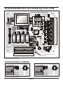
Terminal Identification and numbering of the CP93
Q8
R55
R56
CP93 V1.1 DUAL AC CONTROLLER
R57
T1
A
B
A
Q9
R63
R62
B
R61
Q10
R59
DSP1
ZD7
R21 R20
RL4
F3
R11
C6
RL5
R18 R17
R40
R41
C15
R44
C16
R45
C17
R49
C18
Q7
A
N
E
R
COM
F
R
COM
F
RL6
LIGHT
SOLENOID
JP2
L
JP1
AC MAINS MASTER MTR SLAVE MTR
ZD5
R15 R14
R9
R8
R7
ZD3
C5
C4
R13
R6
R5
ZD2
LD3
A
GA2
GA1
PL1
PB1
A B
A
B
LIGHT SOLENOID
B
A B C D E F G H I
J K L M
N
E
TEST
N.O. CON
R COM F R COM F
AC MAINS MASTER MTR SLAVE MTR
L
N.C. CON
USE DESIGNATED
FUSES ONLY
D11 R46
C8
C7
PL2
F2
Q4
SERIAL NUMBER LABEL
R51
D8
R10
ZD6
R16
R64
K1
R19
ZD4
C9
R12
5 AMP
F/B
ZD9
R22
LD12
Q6
D10
R28
LD9
R47
Q5
D9
RL3
ZD11
R25
GA3
Y1
R48
Q3
D7
RL2
C10
R27 R26
C2
R42
Q2
D6
R23
Q1
R24
C20
R43
U1
R32
R30 R29
C11
R4
VR1
R31
R33
ZD8
LD2
R58
LD1
MAINS ON
RL1
ENTER
STATUS
C3
R2
DOWN
K2
LD13 LD10 LD11
UP
F1
1 AMP
F/B
LD5
C12
DB1
C1
R34
19
18
17
16
15
14
13
12
11
10
9
8
7
6
5
4
3
2
R68
R65
R69
B
R66
R67
SOLENOID RELAY CONTACT
SELECTOR
POWER CONNECTION TERMINALS
Figure 8 Terminal Identification
B
A
B
LIGHT SOLENOID
JP2
SOLENOID
JP1
LIGHT
N.O. CON
JP2
GA1
N.C. CON
B
A
B
LIGHT SOLENOID
N.O. CON
SOLENOID
N.C. CON
LIGHT
JP1
Solenoid Relay Contacts
Figure 10 Normally-closed Contact
Figure 9 Normally-open Contact
Page 16
GA1
1
SIGNAL CONNECTIONS
ZD12
ZD11
C13
LD6
PB4
R35
LD8
PB3
R37
LD4
C14
R36
LD7
R53
C19
R39 R38
R54
PB2
ZD13
D14
D13
R52
R1
*WARNING*
ISOLATE MAINS BEFORE
WORKING ON CARD
5 AMP
F/B
D12
ZD1
R3
D5
MV1
MV3
TRG COM PED BM1 BM2 COM FRX COM STP LED LIT MLO COM MLC SLO COM SLC 12V COM
R60
MV2
Power Connection Terminals
A = Live
B= Neutral
L= Solenoid Relay Contact
AC Mains Input
M= Solenoid Relay Contact
C= Earth
R41
C15
F= Master Motor FORWARD direction winding
R44
C16
R45
C17
C18
AC MAINS MASTER MTR SLAVE MTR
L
N
E
R
COM
F
R
COM
F
RL6
LIGHT
SOLENOID
JP2
R40
JP1
D= Master Motor REVERSE direction winding
E= Master Motor COMMON (neutral)
PL1
N
E R COM F R COM F
AC MAINS MASTER MTR SLAVE MTR
A B
A
B
LIGHT SOLENOID
A B C D E F G H I
J K L M
L
I= Slave Motor FORWARD direction winding
J= Lamp Relay Contact
K= Lamp Relay Contact
N.O. CON
H= Slave Motor COMMON (neutral)
N.C. CON
G= Slave Motor REVERSE direction winding
Figure 11 Power Connection Terminals
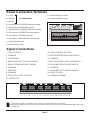
Signal Connections
1 TRIGGER INPUT
11 LIGHT CONTROL BUTTON
2 COMMON
12 MASTER MOTOR OPEN LIMIT SWITCH
3 PEDESTRIAN
13 COMMON
4 BEAM 1 / MOTOR COLLISION SENSE†
14 MASTER MOTOR CLOSE LIMIT SWITCH
5 BEAM 2 [STANDARD SAFETY BEAM]
15 SLAVE MOTOR OPEN LIMIT SWITCH
6 COMMON
16 COMMON
7 FREE-EXIT
17 SLAVE MOTOR CLOSE LIMIT SWITCH
8 COMMON
18 12V DC SUPPLY‡
9 STOP [E.M.G. STOP BUTTON]
19 COMMON (0V/GND)
10 STATUS LED
LD8
LD13 LD10 LD11
LD9
LD12
LD7
LD6
LD5
LD3
LD4
TRG COM PED BM1 BM2 COM FRX COM STP LED LIT MLO COM MLC SLO COM SLC 12V COM
1 2 3 4 5 6 7 8 9 10 11 12 13 14 15 16 17 18 19
Figure 12 Signal Connections
! † Configuration depends on programmed options - refer to programming section later in this manual.
! ‡ This supply is limited and is only sufficient to supply power to a radio and two beams. DO NOT USE FOR SOLENOID LOCK or ANY
OTHER USE.
Page 17
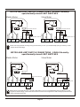
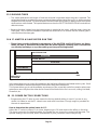
CP93 Electrical Set-up
MOTOR AND LIMIT SWITCH CONNECTIONS - DOUBLE Normallyopen/Normally-closed LIMIT SWITCHES
Master Motor
Slave Motor
D
E
F
12
13
14
G
H
SLC
SLO
COM
Closed Limit Switch
FORWARD
Open Limit Switch
REVERSE
MLC
MLO
FORWARD
COM
REVERSE
Open Limit Switch
I
15
16
Closed Limit Switch
17
!CP93 must be programmed according to the type of limit switch you use. If you install Normally-open type switches you must
program the card accordingly.
MOTOR AND LIMIT SWITCH CONNECTIONS - SINGLE Normallyopen/Normally-closed LIMIT SWITCHES
D
E
F
12
13
14
G
H
I
SLO
FORWARD
COM
Single Limit Switch
REVERSE
Slave Motor
FORWARD
MLO
COM
REVERSE
Master Motor
Single Limit Switch
15
16
17
!CP93 must be programmed according to the type of limit switch you use. If you install Normally-open type switches you must
program the card accordingly. The wire links must be fitted as shown for this configuration as well as the appropriate limit switch
mode programmed into the card.
Figure 13 Motor and Limit Switch Connections -Double Normally/Single Normally
Page 18
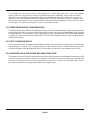
CP93 Electrical Set-up
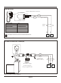
RADIO CONNECTIONS
CENTSYS
SMART
RECEIVER
ERASE
{
12 - 24V
AC/DC
COM
N.C.
N.O.
LEARN
TRANSMITTER
RECEIVER
NO CODING
SWITCHES
1 2 3 4 5
+12V
COM
TRG
18
19
1
TRG
+12V
COM
Example 2 - Using a generic radio
TRANSMITTER
TYPICAL RADIO RECEIVER
0.5MM²
Cable
+12V
COM
NC NO
+12V
TRG
{
{
0V
+12V
{
POWER
SUPPLY
COM
CODE SWITCHES
(Refer to user manual of the
product for programming details)
Optional external link if not internally fitted
Figure 14 Radio Connections
INTERCOM CONNECTIONS
Intercom
GND
TRG
0.5MM²
CABLE
2
1
!Many different types of intercom exist. The connections shown are only those that are necessary to interface to the CP93.
Please consult the documentation of the intercom for full wiring diagrams.
Figure 15 Intercom Connections
Page 19
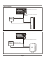
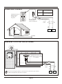
SOLENOID / MAGNETIC LOCK
SOL
SOL
SOL
SOL
BROWN
BROWN
Option A - Solenoid Lock
AC
AC
CP13E PSU
0.5mm²
CABLE
EN
L
Option B - Magnetic Lock
N
AC
Mains
L
M
M
18
12V RELAY
+12V
SOL
S
RED
BLK
19
CP84E PSU
EN
L
AC
Mains
Figure 16 Solenoid/Magnetic Lock
Page 20
L
LOCK RELEASE
R44
C16
N
E
R45
C17
R
COM
F
R49
C18
R
COM
LIGHT
SOLENOID
Solenoid Relay Contact Selector
D11 R46
RL6
F
JP2
R41
C15
AC MAINS MASTER MTR SLAVE MTR
L
JP1
R40
A B
A
B
LIGHT SOLENOID
N.O. CON
N
E R COM F R COM F
AC MAINS MASTER MTR SLAVE MTR
L
N.C. CON
PL1
Select Normally-closed Contact
Separate Power Supply
PSU
Maglock
Figure 17 Magnetic Lock Release
R44
C16
R45
C17
L
N
E
R
COM
F
Solenoid Relay Contact Selector
R49
C18
R
COM
F
RL6
LIGHT
SOLENOID
D11 R46
JP2
R41
C15
AC MAINS MASTER MTR SLAVE MTR
JP1
R40
A B
A
B
LIGHT SOLENOID
N.O. CON
N
E R COM F R COM F
AC MAINS MASTER MTR SLAVE MTR
L
N.C. CON
PL1
Select Normally-open Contact
PSU
Separate Power Supply
Electric Lock
Figure 18 Solenoid Lock Release
Page 21
CP93 Electrical Set-up
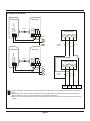
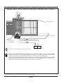
INFRARED BEAMS
RECEIVER
Beam
POWER
SUPPLY
COMMON
POWER 12V DC
SUPPLY
TRANSMITTER
N/O
N/C
INFRARED BEAM
+12V
NEG
N/C
LINK
NEG
+12V
N/C
POWER
SUPPLY
COMMON
RECEIVER
Beam
POWER
SUPPLY
COMMON
POWER 12V DC
SUPPLY
TRANSMITTER
0,2mm²
Cable
N/O
N/C
INFRARED BEAM
+12V
NEG
N/C
18
19
4
LINK
NEG
+12V
N/C
0,2mm²
Cable
5
!Opening safety beam is optional. if the opening safety beam is not fitted, place a wire bridge between BM1 (pin 4) and common
(pin6).
!Input pin BM1 (pin 4) cannot be used for a beam and as a motor stall/collision sense input at the same time. Ensure that the
Mode of Operation of this pin is correctly programmed for the intended configuration.
!Make sure you use the Normally-closed contacts of the beam relay and not the Normally-open contacts as is the case with other
products.
Figure 19 Infrared Beams
Page 22
CP93 Electrical Set-up
PEDESTRIAN KEYSWITCH
Spring Return Switch
Signal Common
NEG
PED
0,2mm²
CABLE
PED
COM
Control Box
3
2
Figure 20 Pedestrian Keyswitch
FREE-EXIT LOOP
NEG
LD101 - 12V DC
loop detector
unit
Control Box
OUT
0,2mm
Cable
Twisted Wires
from loop
8
Underground
Loop
1 2
+ -
3
7
6
2
5
11 Pin Plug in relay base
12V AC/DC
Supply
Figure 21 Free-exit Loop
Page 23
7
6
CP93 Electrical Set-up
STATUS LED
Fitted to Handset Base Separately
Anode +
LED
Cathode -
NEG
Signal Common
Status Led
OFF
ON
SLOW EVEN FLASH
FAST EVEN FLASH
1 SHORT FLASH/2 SEC
SHORT FLASHES
5 EVEN FLASHES
0,2mm²
Cable
!These flashes can also be observed on the status LED of the card.
LED
COM
GATE CLOSED
GATE OPEN
GATE OPENING
GATE CLOSING
PILLAR LAMP OVERRIDE
EMERGENCY STOP
POWER UP
3
2
Figure 22 Status LED
PILLAR/COURTESY LAMP(S)
LIGHT
LIVE
2
0,5mm Norsk
Cable or (S.W.A.)
}
E N L
220-240V AC Supply
(or other voltage to
suit type of globes used)
Figure 23 Pillar / Courtesy Lamp(s)
Page 24
J
K
PILLAR LIGHT CONTROL
Pushbutton Switch is
Shown Fitted to
an Intercom
Telephone
Press
Turns Pillar Light on
for Programmed Time
Hold 3 Sec
Turns Pillar
Light on Permanently
LIGHT
NEG
Signal Common
0,2mm
Cable
2
LIT
COM
Normally-open
Contact Pushbutton
3
2
TO CP93
Figure 24 Pillar Light Control
EMERGENCY STOP BUTTON (OPTIONAL)
Standard Emergency Stop
Safety Button (twist-to-reset)
n.c. contacts
STP
NEG
If you are not using this feature, you must fit a wire link across pins 8 and 9.
Card will not function if the link is not fitted.
Figure 25 Emergency Stop Button (optional)
Page 25
8
STP
COM
0,2mm
Cable
9
CP93 Electrical Set-up
BEAM 1 INPUT USED FOR MOTORS WITH CENTRIFUGAL CONTACT
Single Slide Gate
BM1
6
Bm1
NEG
COM
Motor with
centrifugal switch
(e.g. Hansa-Matic)
4
Card must be programmed for this configuration to work.
! In this mode, the centrifugal switch has the same action as a beam, if the motor stalls as a result of, for example, pushing
against an obstruction in its path, the CP93 will sense this on the beam 1 input. The action will be a stop-reverse sequence.
! To implement the other modes such as CONDO and PIRAC, it is still necessary to install a safety beam
! The time it takes for the centrifugal switch to come in after the motor has started is fixed to roughly one second. In situations
where the CP93 is to replace an existing board, be sure that the motor does spin up within 1 second. In other words, the
centrifugal switch must have been activated within a second after the motor is started.
Figure 26 Beam 1 Input Used for Motor with Centrifugal Contact
Page 26
CP93 Programming
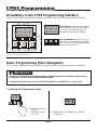
Orientation in the CP93 Programming Interface
The CP93 has a built-in programming interface consisting of an LED display and three pushbuttons.
Q8
Q9
Q10
DSP1
ZD1
R3
D12
C19
R53
The Display shows the information
about the card's settings and allows
the user to see what options are
available to change the settings.
R39
D14
D13
PB3
PB4
R54
PB2
R52
PB2
PB3
UP
DOWN
C13
C12
UP
DOWN
ENTER
STATUS
K2
PB4
R36
ENTER
The Pushbuttons allow the user to
edit values, change settings and to
gain access to all the programmable
features of the product.
R33
ZD8
R30
Figure 27 Programming Interface
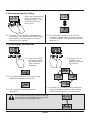
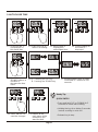
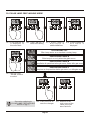
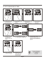
Basic Programming Menu Navigation
The CP93 has a built-in programming interface consisting of an LED display and three pushbuttons.
IMPORTANT
Normal card operation is suspended when programming mode is selected. Gates cannot
be opened or closed whilst in programming mode.
Programming mode can only be invoked if the gate has completed it's current cycle.
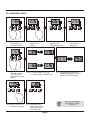
1. Invoking the Programming Menu
UP
DOWN
ENTER
1.1. Press and hold the
"ENTER"
pushbutton for 2
seconds.
1.2. Display turns on. Release the "ENTER"
pushbutton.
Page 27
2. Selecting an Item for Editing
When the Programming
menu is invoked, the
display shows "1". This
is the first item in the
main menu.
UP
DOWN
ENTER
2.1. Press the "UP" or "DOWN" pushbuttons to
increment or decrement to the desired menu
item number. Hold the button for at least 1
second to scroll rapidly.
2.2. The main menu contains up to 25 items.
Scrolling upwards past 25 causes a wrap to
number 1, while scrolling downwards past 1
wraps to 25.
3. Accessing the Selected Item
UP
DOWN
ENTER
UP
3.1. Press the "ENTER"
pushbutton while
the desired menu
item number is
displayed
DOWN
ENTER
3.3. Press the "UP" or
"DOWN" push
buttons to change
the settings
3.2. The abbreviated name of the item being
edited is displayed for 1 second.
3.2. The currently programmed value is
displayed
3.4. Pressing UP or DOWN cycles through the
various available options for the currently
selected menu item in a circular fashion.
BUT, for menu items that contain numerical
data, the "UP" and "DOWN" keys increment,
or decrement the displayed value
Page 28
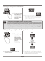
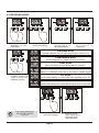
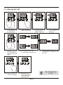
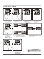
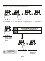
4. Saving your Changes to the Selected Item
UP
DOWN
ENTER
4.1. To save your change
(or to return to the
main menu if
nothing has been
changed) simply
press the "ENTER"
pushbutton.
4.2. The changes are saved to non-volatile storage
with confirmation ("Set" is briefly displayed)
and the display returns to the last selected
position in the main menu.
Aborting the Programming Menu to Discard Changes
If you have changed something and you are unsure about it and want to exit the menu system
and discard your changes, there is an easy way to do this: To exit the Programming menu and
return to normal operation, simply refrain from pressing any of the buttons for 20 seconds.
After 30 seconds have elapsed the menu will expire and the card will return to operational
mode. All changes made however, will be lost and the previous set of settings will apply. This
only applies if you have an edited setting on the display and have NOT yet pressed "ENTER".
5. Exiting the Programming Menu after Changes have been made
OR
UP
DOWN
ENTER
5.1. To save all changes
and exit the
programming
menu, i.e. to go
back into normal
operational mode,
press the "UP" and
"ENTER"
pushbuttons
simultaneously.
5.2. The display turns off and normal card
operation resumes.
wait 30 seconds
5.3. Leave the card, i.e. don't press any keys for
at least 30 seconds and the card will exit the
programming menu automatically!
Page 29
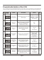
Programmable Options of the CP93
This is a table of all the programmable features of the CP93. For the convenience of the experienced
installer, this table includes the number of the page where the specific details of the feature may be found.
Abbrev.
Name
Feature
Description
Options
Pg
1
Limit Switch
Configuration
Programmable Options for Limit
Switch Types
Double N.C. Contact
Double N.O. Contact
Single N.C. Contact
Single N.O. Contact
Free Running
33
2
Autoclose
Function
Turn Autoclose function ON/OFF
(Note: This setting is forced to
ON and is not editable in
CONDO/PIRAC mode)
OFF
ON
34
3
Autoclose
Time
Time delay that must expire
before Autoclose function
activates
1 second
to
255 seconds
35
36
No.
4
OPERATING
MODE
Selection of the OPERATING
MODE of the product
STANDARD MODE
CONDO MODE
PIRAC MODE
REVERSING MODE
PLC MODE
DEADMAN MODE
5
Pedestrian
AUTOCLOSE
Time
Time delay that must expire
before a pedestrian gate is
automatically closed
1 second
to
255 seconds
37
6
Pillar/Courtesy
Light
Length of time that the Pillar/
Courtesy light remains on for
after the gate is closed
10 seconds
to
255 seconds
38
7
Pedestrian
RUN time
Length of time that the MASTER
motor must run to open the gate
sufficiently wide enough to allow
pedestrians to enter
1 second
to
255 seconds
0 = turned off
39
Page 30
.
Abbrev.
Name
Feature
Description
Options
Pg
8
Autoclose
Override
Length of time that the TRIGGER
button must be held to invoke
AUTOCLOSE override
1 second
to
255 seconds
40
9
Safety Type on
BM1 Terminal
No.
Normally-closed
(for standard i5 beam)
Programs the functionality of the
BM1 Terminal
Normally-open Delayed
41
(Centrifugal switch)
10
Programming of the Pre-Flash/
Pillar Lamp
Pre-flashing
Flash Modes of the Pillar Lamp/
Mode of Operation
Courtesy Light
Pre-Flash PFF
Mode A
Mode B
Mode C
42
11
Pre-Flashing
Time
Length of time that the Pillar lamp
pre-flashes (only applicable if
preflashing mode has been
selected
1 second
to
255 seconds
43
12
Reversal Delay
Time
Motor Reversal Delay Time
0.1 second
to
25.5 seconds
44
13
Leaf Delay
Order Selection
Selection of which gate opens
first, i.e. which gate is defined
as MASTER
A-B
B-A
45
14
Leaf Delay Time
Time delay between master and
slave gate to allow for
leaf clearance
1 second
to
255 seconds
46
15
Solenoid/
Magnetic
Lock Timer
Length of time that the card will
energize the solenoid/magnetic
lock when opening the gate
1 second
to
255 seconds
47
16
Master Motor
run time
Length of time that the MASTER
motor must run for to open the
gate fully
1 second
to
255 seconds
48
Page 31
Abbrev.
Name
Feature
Description
Options
Pg
17
Slave Motor
run time
Length of time that the SLAVE
motor must run for to open the
gate fully
1 second
to
255 seconds
49
18
Power Factor
Relay 1
Adjusts the phase angle of
Relay 1
[MASTER CLOSE]
-10
to
+10
50
19
Power Factor
Relay 2
Adjusts the phase angle of
Relay 2
[MASTER OPEN]
-10
to
+10
51
20
Power Factor
Relay 3
Adjusts the phase angle of
Relay 3
[SLAVE CLOSE]
-10
to
+10
52
21
Power Factor
Relay 4
Adjusts the phase angle of
Relay 4
[SLAVE OPEN]
-10
to
+10
53
22
Mains
Frequency
Selection of the line frequency
50Hz
60Hz
54
23
Pedestrian
Mode Error
Compensation
Lengthens the closing cycle in
Pedestrian Mode to compensate
for positioning error
1 - 255 seconds
(0 = disabled)
55
24
Post-Solenoid
Delay
Delays motor activation for the
preset time after the solenoid
becomes active
1 - 255 seconds
(0 = disabled)
56
25
Solenoid Lock
Pressure Release
Mode
Enables/Disables the solenoid
lock strain relief routine that
is executed each time the gate
is opened
ON/OFF
57
No.
Page 32
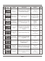
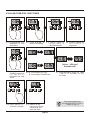
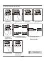
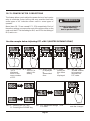
Programming each Menu Item
1. LIMIT SWITCH CONFIGURATION
1.1. Scroll until the "1"
is displayed, i.e.
this menu item
1.2. Press "ENTER" to
select it for editing
1.3. Menu name is
displayed in
abbreviated form
1.4. Current setting for
this menu is
displayed
DOUBLE NORMALLY-CLOSED CONTACTS
Applicable to both sets of OPEN and CLOSED limit switches
DOUBLE NORMALLY-OPEN CONTACTS
Applicable to both sets of OPEN and CLOSED limit switches
SINGLE NORMALLY-CLOSED CONTACTS
Applicable to the single limit switch on each motor
SINGLE Normally-open CONTACTS
Applicable to the single limit switch on each motor
1.5. Use "UP" and
"DOWN" buttons to
select desired
configuration from
the available
FREE RUN
No limit switches - uses run times to determine limits
See page 18 for corresponding
electrical configurations!
Also see notes referring to
1.6. Press "ENTER" to
LIMIT SWITCH
save the changes
CONFIGURATION on pg 55
Page 33
1.7. Returns to the
main menu at the
same point you
were last time
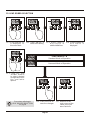
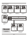
2. AUTOCLOSE FUNCTION
2.1. Scroll until the "2"
is displayed, i.e.
this menu item
2.2. Press "ENTER" to
select it for editing
2.3. Menu name is
displayed in
abbreviated form
2.4. Current setting for
this menu is
displayed
AUTOCLOSE FUNCTION OFF
Gate stays open, has to be closed by command
AUTOCLOSE FUNCTION ON
Gate automatically closes after preset time
2.5. Use "UP" and
"DOWN" buttons to
select desired
configuration from
the available
options.
See notes referring to
AUTOCLOSE FUNCTION
on pg 55
2.6. Press "ENTER" to
save the changes
Page 34
2.7. Returns to the
main menu at the
same point you
were last time
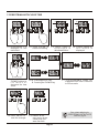
3. AUTOCLOSE TIME
3.1. Scroll until the "3"
is displayed, i.e.
this menu item
3.2. Press "ENTER" to
select it for editing
3.3. Menu name is
displayed in
abbreviated form
3.4. Current setting for
this menu is
displayed
A
B
3.5. Use "UP" and
"DOWN" buttons to
increase or
decrease the time
value.
3.6. A - Pressing the "UP" key
B - Pressing the "DOWN" key
3.7. Programmable range for AutoClose time is 1 second to 255
seconds
Handy Tip:
QUICK ENTRY
• Press and hold "UP" or "DOWN" for 2
seconds to invoke fast scrolling.
• Holding the key for a further 5 seconds
invokes scrolling in units x10
3.8. Press "ENTER" to
save the changes
3.9. Returns to the
main menu at the
same point you
were last time
Page 35
• Release key to stop
4. OPERATING MODE
4.1. Scroll until the "4" is 4.2. Press "ENTER" to 4 . 3 . M e n u n a m e i s 4.4. Current setting for
displayed, i.e. this
select it for editing
displayed in
this menu is
menu item
abbreviated form
displayed
STANDARD MODE
Standard feature set with start-stop-reverse sequencing
CONDOMINIUM MODE
Mode designed for communal living schemes
PIRAC MODE
Autoclose when broken safety beam is restored
REVERSING MODE
Variation of STANDARD Mode with no stop stage in multiple triggers
4.5. Use "UP" and
"DOWN" buttons to
scroll through the
available options.
PLC MODE
Special mode allowing for control with pulse signalling from a PLC
DEAD MAN MODE
Special mode allowing for control with fail-safe in event of signal loss
See notes referring to
OPERATING MODE
on pg 55
4.6. Press "ENTER" to
save the changes
Page 36
4.7. Returns to the
main menu at the
same point you
were last time
5. PEDESTRIAN AUTOCLOSE TIME
5.1. Scroll until the "5" is 5.2. Press "ENTER" to 5 . 3 . M e n u n a m e i s 5.4. Current setting for
displayed, i.e. this
select it for editing
displayed in
this menu is
menu item
abbreviated form
displayed
A
B
5 . 5 . U s e " U P " a n d 5.6. A - Pressing the "UP" key
"DOWN" buttons to
B - Pressing the "DOWN" key
increase or
decrease the time
value.
5.8. Press "ENTER" to
save the changes
5.9. Returns to the
main menu at the
same point you
were last time
Page 37
5.7. Programmable range for
Pedestrian Autoclose time is 1
second to 255 seconds
See notes referring to
PEDESTRIAN AUTOCLOSE
TIME on pg 55
6. PILLAR/COURTESY LIGHT TIMER
6.1. Scroll until the "6" is 6.2. Press "ENTER" to 6 . 3 . M e n u n a m e i s 6.4. Current setting for
displayed, i.e. this
select it for editing
displayed in
this menu is
menu item
abbreviated form
displayed
A
[10 sec - 2550 sec]
Seconds (x10)
B
6 . 5 . U s e " U P " a n d 6.6. A - Pressing the "UP" key
"DOWN" buttons to
B - Pressing the "DOWN" key
increase or
decrease the time
value.
6.8. Press "ENTER" to
save the changes
6.9. Returns to the
main menu at the
same point you
were last time
Page 38
6.7. Programmable range for Light
Time is 10 seconds to 255
seconds
See notes referring to
PILLAR/COURTESY LIGHT
TIMER on pg 55
7. PEDESTRIAN AUTOCLOSE TIME
7.1. Scroll until the "7" is 7.2. Press "ENTER" to 7 . 3 . M e n u n a m e i s 7.4. Current setting for
displayed, i.e. this
select it for editing
displayed in
this menu is
menu item
abbreviated form
displayed
A
B
7 . 5 . U s e " U P " a n d 7.6. A - Pressing the "UP" key
"DOWN" buttons to
B - Pressing the "DOWN" key
increase or
decrease the time
value.
7.8. Press "ENTER" to
save the changes
7.9. Returns to the
main menu at the
same point you
were last time
Page 39
7.7. Programmable range for
Pedestrian Run Time is 1 second
to 255 seconds
See notes referring to
PEDESTRIAN AUTOCLOSE
TIME on pg 56
8. AUTOCLOSE OVERRIDE TIMER
8.1. Scroll until the "8" is 8.2. Press "ENTER" to 8 . 3 . M e n u n a m e i s 8.4. Current setting for
displayed, i.e. this
select it for editing
displayed in
this menu is
menu item
abbreviated form
displayed
A
B
8 . 5 . U s e " U P " a n d 8.6. A - Pressing the "UP" key
"DOWN" buttons to
B - Pressing the "DOWN" key
increase or
decrease the time
value.
8.8. Press "ENTER" to
save the changes
8.9. Returns to the
main menu at the
same point you
were last time
Page 40
8.7. Programmable range for
Autoclose Override timer is 1
second to 255 seconds
See notes referring to
AUTOCLOSE OVERRIDE
TIMER on pg 56
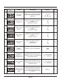
9. SAFETY TYPE CONFIGURATION OF BM1 TERMINAL
9.1. Scroll until the "9" is 9.2. Press "ENTER" to 9 . 3 . M e n u n a m e i s 9.4. Current setting for
displayed, i.e. this
select it for editing
displayed in
this menu is
menu item
abbreviated form
displayed
Normally-closed
Configured for OPENING beam on BM1 Terminal
Normally-open DELAYED
Configured for centrifugal switch motor signal
9.5. Use "UP" and
"DOWN" buttons to
select.
See notes referring to
9.6. Press "ENTER" to
SAFETY TYPE CONFIGURATION
save the changes
OF BM1 TERMINAL
on pg 56
Page 41
9.7. Returns to the
main menu at the
same point you
were last time
10. PILLAR LAMP PREFLASHING MODE
10.1. Scroll until the "10" 10.2. Press "ENTER" to 10.3. Menu name is 10.4. Current setting for
is displayed, i.e.
select it for editing
displayed in
this menu is
this menu item
abbreviated form
displayed
PREFLASHING OFF
Pillar Lamp works as a standard courtesy lamp
PREFLASHING MODE A
Pillar Lamp is on only when the gates move
PREFLASHING MODE B
Lamp flashes for preset time before gate moves, flashes while gate moves
PREFLASHING MODE C
Lamp turns on for preset time before gate moves, on while gate moves
10.5. Use "UP" and
"DOWN" buttons
to select.
10.6. Press "ENTER" to
See notes referring to
save the changes
PILLAR LAMP PREFLASHING
MODE on pg 57
Page 42
10.7. Returns to the
main menu at the
same point you
were last time
11. PREFLASHING TIME
11.1. Scroll until the "11" 11.2. Press "ENTER" to 11.3. Menu name is 11.4. Current setting for
is displayed, i.e.
select it for editing
displayed in
this menu is
this menu item
abbreviated form
displayed
A
B
11.5. Use "UP" and 11.6. A - Pressing the "UP" key
"DOWN" buttons
B - Pressing the "DOWN" key
to increase or
decrease the time
value.
11.8. Press "ENTER" to
save the changes
11.9. Returns to the
main menu at the
same point you
were last time
Page 43
11.7. Programmable range for Preflashing time is 1 second to 255
seconds
See notes referring to
PRE-FLASHING TIME
on pg 58
12. MOTOR REVERSAL DELAY TIME
12.1. Scroll until the
12.2. Press "ENTER" to
"12" is displayed,
select it for
i.e. this menu item
editing
12.3. Menu name is
displayed in
abbreviated form
12.4. Current setting for
this menu is
displayed
A
0.1 sec
B
12.5. Use "UP" and
"DOWN" buttons
to increase or
decrease the time
value.
12.8. Press "ENTER" to
save the changes
25.5 sec
Seconds (x 0.1)
12.6. A - Pressing the "UP" key
B - Pressing the "DOWN" key
12.9. Returns to the
main menu at the
same point you
were last time
Page 44
12.7. Programmable range for
Reversal Delay Time is 0.1
second to 25.5 seconds.
Setting of zero disables
reversal delay timer.
See note referring to
MOTOR REVERSAL DELAY
TIME on pg 58
13. LEAF ORDER SELECTION
13.1. Scroll until the "13" 13.2. Press "ENTER" to 13.3. Menu name is 13.4. Current setting for
is displayed, i.e.
select it for editing
displayed in
this menu is
this menu item
abbreviated form
displayed
LEAF ORDER A - B
Standard Mode of Operation
LEAF ORDER B - A
Reversed Mode of Operation
13.5. Use "UP" and
"DOWN" buttons
to select desired
configuration from
the available
options
See notes referring to
LEAF ORDER SELECTION
on pg 58
13.6. Press "ENTER" to
save the changes
Page 45
13.7. Returns to the
main menu at the
same point you
were last time
14. LEAF DELAY TIME
14.1. Scroll until the
"14" is displayed,
i.e. this menu
14.2. Press "ENTER" to
select it for
14.3. Menu name is
displayed in
abbreviated form
14.4. Current setting for
this menu is
displayed
A
B
14.5. Use "UP" and
"DOWN" buttons
to increase or
decrease the time
value.
14.8. Press "ENTER" to
save the changes
14.6. A - Pressing the "UP" key
B - Pressing the "DOWN" key
14.9. Returns to the
main menu at the
same point you
were last time
Page 46
14.7. Programmable range for Leaf
Delay Time is 1 second to 255
seconds.
Leaf delay mode is disabled
with a setting of zero.
See note referring to
LEAF DELAY TIME
on pg 58
15. SOLENOID TIMER
15.1. Scroll until the "15" 15.2. Press "ENTER" to
is displayed, i.e.
select it for
this menu item
editing
15.3. Menu name is
displayed in
abbreviated form
15.4. Current setting for
this menu is
displayed
A
B
15.5. Use "UP" and
"DOWN" buttons
to increase or
decrease the time
value.
15.8. Press "ENTER" to
save the changes
15.6. A - Pressing the "UP" key
B - Pressing the "DOWN" key
15.9. Returns to the
main menu at the
same point you
were last time
Page 47
15.7. Programmable range for
Solenoid Energise Time is 1
second to 255 seconds.
See note referring to
SOLENOID TIMER
on pg 59
16. MASTER MOTOR RUN TIME
16.1. Scroll until the "16" 16.2. Press "ENTER" to
is displayed, i.e.
select it for
this menu item
editing
16.3. Menu name is
displayed in
abbreviated form
16.4. Current setting for
this menu is
displayed
A
B
16.5. Use "UP" and
"DOWN" buttons
to increase or
decrease the time
value.
16.8. Press "ENTER" to
save the changes
16.6. A - Pressing the "UP" key
B - Pressing the "DOWN" key
16.9. Returns to the
main menu at the
same point you
were last time
Page 48
16.7. Programmable range for
Master Motor Run Time is 1
second to 255 seconds.
See note referring to
MASTER MOTOR RUN TIME
on pg 59
17. SLAVE MOTOR RUN TIME
17.1. Scroll until the
"17" is displayed,
i.e. this menu
17.2. Press "ENTER" to
select it for
17.3. Menu name is
displayed in
abbreviated form
17.4. Current setting for
this menu is
displayed
A
B
17.5. Use "UP" and
"DOWN" buttons
to increase or
decrease the time
value.
17.8. Press "ENTER" to
save the changes
17.6. A - Pressing the "UP" key
B - Pressing the "DOWN" key
17.9. Returns to the
main menu at the
same point you
were last time
Page 49
17.7. Programmable range for Slave
Motor Run Time is 1 second to
255 seconds.
See note referring to
SLAVE MOTOR RUN TIME
on pg 59
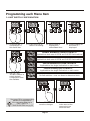
18- 21. POWER FACTOR CORRECTIONS
This feature allows you to adjust the power factor of each motor
relay to eliminate contact arcing that may manifest itself with
some types of AC induction motor used in some types of
operator.
Menu Items 18 - 21 are named PF1 - PF4 respectively. Each of
these four settings correspond to each of the motor relays on the
card such that PF1 is the setting for RL1, and PF2 is the setting of
RL2, and so on...
WARNING!
Incorrect programming of
these items may
lead to product failure!
See the example below: Adjusting PFC of RL2 (MASTER OPENING RELAY)
18.1. Scroll until the 18.2. Press
"19" is
"ENTER" to
displayed,
select it for
which is the
editing
menu number
of PF2
18.3. Menu name 18.4. Current
is displayed
setting for
in
this menu
abbreviated
is
form
displayed
18.5. Use "UP" and
"DOWN" buttons
to increase or
decrease the
PFC value
A
B
18.6. A - Pressing the "UP" key
B - Pressing the "DOWN" key
18.7. PFC Adjustment Range -10 to
+10 units
Page 50
18.8. Press "ENTER" to
save the changes
22. MAINS FREQUENCY
22.1. Scroll until the "2"
is displayed, i.e.
this menu item
22.2. Press "ENTER" to
select it for
editing
22.3. Menu name is
displayed in
abbreviated form
22.4. Current setting for
this menu is
displayed
50Hz
Mains frequency setting for RSA, UK and most of Europe
60Hz
Mains frequency setting for USA and Canada
22.5. Use "UP" and
"DOWN" buttons
to cycle through
the options
available
WARNING!
Incorrect programming of
this item may
lead to product failure!
22.6. Press "ENTER" to
save the changes
Page 51
22.7. Returns to the
main menu at the
same point you
were last time
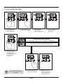
23. PEDESTRIAN MODE ERROR COMPENSATION
23.1. Scroll until the "16" 23.2. Press "ENTER" to
is displayed, i.e.
select it for
this menu item
editing
23.3. Menu name is
displayed in
abbreviated form
23.4. Current setting for
this menu is
displayed
A
B
23.5. Use "UP" and
"DOWN" buttons
to increase or
decrease the time
value.
23.8. Press "ENTER" to
save the changes
23.6 . A - Pressing the "UP" key
B - Pressing the "DOWN" key
23.9. Returns to the
main menu at the
same point you
were last time
Page 52
23.7. Programmable range for
Pedestrian Compensation
Time is 1 second to 255
seconds. A setting of zero
disables (turns off) this feature.
See note referring to
PEDESTRIAN MODE ERROR
COMPENSATION
on pg 60
24. POST SOLENOID DELAY TIMER
24.1. Scroll until the "16" 24.2. Press "ENTER" to
is displayed, i.e.
select it for
this menu item
editing
24.3. Menu name is
displayed in
abbreviated form
24.4. Current setting for
this menu is
displayed
A
B
24.5. Use "UP" and
"DOWN" buttons
to increase or
decrease the time
value.
24.8. Press "ENTER" to
save the changes
24.6 . A - Pressing the "UP" key
B - Pressing the "DOWN" key
24.9. Returns to the
main menu at the
same point you
were last time
Page 53
24.7. Programmable range for Post
Solenoid Delay Timer is 1
second to 255 seconds. A
setting of zero disables this
feature.
See note referring to
POST SOLENOID
DELAY
on pg 60
25. SOLENOID LOCK PRESSURE RELEASE FUNCTION
25.1. Scroll until the "13" 25.2. Press "ENTER" to 25.3. Menu name is 25.4. Current setting for
is displayed, i.e.
select it for editing
displayed in
this menu is
this menu item
abbreviated form
displayed
LOCK PRESSURE RELEASE ROUTINE OFF
Gate operates in the standard manner
LOCK PRESSURE RELEASE ROUTINE ON
Gates are pulled against limits to relieve strain on lock
25.5. Use "UP" and
"DOWN" buttons
to select desired
configuration from
the available
options
See notes referring to
SOLENOID LOCK
PRESSURE RELEASE
FUNCTION on pg 60
25.6. Press "ENTER" to
save the changes
Page 54
25.7. Returns to the
main menu at the
same point you
were last time
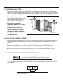
Programming Notes
1. LIMIT SWITCH CONFIGURATION
• In FREE RUN configuration, you do not need to fit wire links to the limit switch terminals. It is
acceptable to leave them open.
2. AUTOCLOSE FUNCTION
• This feature is forced to the "ON" setting and cannot be changed if the CONDO or PIRAC Mode
is selected. You will not be able to make changes if these modes are programmed.
4. OPERATING MODE
• PLC and DEADMAN Mode require special electrical configurations! In PLC Mode, the
TRIGGER and FREE-EXIT terminals become the control pulse inputs. The TRIGGER pin accepts
CLOSING command pulses, and the FREE-EXIT pin accepts OPENING command pulses. The
CP93 responds on the falling edge of the pulse. The pulse width must be at least 500mS long.
• In DEADMAN Mode, the TRIGGER and FREE-EXIT pins become CLOSE and OPEN signalling
inputs respectively. The gate will freeze state, i.e. gate stops completely if a signal should fall
away before the gate has reached it's limits.
• PLC and DEADMAN Mode cannot work without limit switches. You must fit limit switches to the
motors or gates if these modes are to be used successfully.
• In both the PLC and DEAD MAN Mode it is not possible to have a FREE-EXIT button because
that terminal is then reserved for controlling the gate.
• Selecting either CONDO or PIRAC Mode will force AUTOCLOSE to on the "ON" setting
automatically. In these modes it's not possible to turn it off in the menu.
5. PEDESTRIAN AUTOCLOSE TIME
• This timer determines how long the gate will stay open for a pedestrian. Care should be
exercised to program it such that the gate does not remain open too long after it has opened for
security, but, at the same time must be sufficiently long to allow pedestrians to walk through.
6. PILLAR/COURTESY LIGHT TIMER
• This timer determines how long the pillar lamp remains on after a gate cycle has completed. It
also specifies the length of on-time when the light control button is pressed.
• In other modes this time is the actual time the lamp remains on, and is not related to pre-flash
times, etc.
Page 55
7. PEDESTRIAN RUN TIME
• This timer determines how far the MASTER gate will open to allow a space for pedestrians to
enter. THIS TIMER MAY NEVER BE EQUAL TO, OR LONGER THAN ANY OF THE MOTOR RUN
TIMES. This timer is set typically that the gate will only open to about 30-45 degrees as shown.
• The width of the opening allowed
is just sufficient for people to enter.
Adjust the pedestrian run time to
alter the size of this opening.
• The closing cycle of the
pedestrian mode is such that it
will always attempt to close onto
the limit switch. In free-run
mode the pedestrian run-time
applies and may be compensated to be longer than the
opening run-time in menu item
23 to cancel out the position
error that occurs.
Figure 28 Gate Opening at 30-45°
8. AUTOCLOSE OVERRIDE TIMER
• Setting this timer longer than the run time or cycle time of the gate, or to zero will prevent Autoclose override from being invoked. You may do this to disable the ACO feature for security
reasons.
• Autoclose override mode may only be invoked in STANDARD and REVERSING Modes.
• Note that this feature only works on a per-cycle basis and is cleared once the gate cycle is
completed.
9. SAFETY TYPE CONFIGURATION OF BM1 TERMINAL
Normally-closed
Configuration for OPENING beam on BM1 Terminal
• In this configuration, connect an opening beam to the BM1 terminal as shown on page 22. If you
do not want to use an opening beam, simply fit a wire link between BM1 terminal and COM as
shown below.
6
Figure 29 Wire Link
Page 56
4
9. SAFETY TYPE CONFIGURATION OF BM1 TERMINAL continued...
Normally-open DELAYED
Configuration for centrifugal switch motor signal (HANSA-MATIC,etc.)
• This is the special mode to accommodate gate motors which have a centrifugal switch. Refer to
page 26 for exact wiring details.
• The connections from the switches of both motors may be connected in parallel. The only
drawback is that both
gates will be reversed if an
obstruction is encountered
that stalls the motor.
• For newer motors that do
not have the centrifugal
switch, but have a
magnetic pick-up,
CENTSYS provides an
interface module to
generate a compatible
signal for this pin from the
pick-up signal. Please
contact CENTSYS for more
details and availability.
BM1
NEG
Figure 30 Normally-Open Delayed Configuration
10. PILLAR LAMP PRE-FLASHING MODE
• Selecting any of the three pre-flashing modes (A, B or C) disables Pillar Lamp control via
the button input terminal [TERMINAL 11].
Please note that if you change the pre-flashing setting to "OFF" from a previous setting, the light
control button [TERMINAL 11] may only begin to respond after the next gate cycle has
occurred.
• Pre-flash MODE A turns the Pillar Lamp on only when the gate moves, therefore the lamp control
relay may be used to control warning lamps or other equipment that may be attached such as
barriers, indicators, robots, etc.
• Pre-flash MODE B flashes the lamp for a pre-set amount of time (MENU 11 specifies this amount
of time on page 43.) The lamp flashes while the gate moves. When the gate reaches a limit, the
lamps stops flashing. In this mode the lamp is intended to be a warning lamp.
• Pre-flash MODE C turns the lamp on for a pre-set amount of time (MENU 11 specifies this
amount of time on page 43.) The lamp remains on while the gates move. When the gates reach
a limit, the lamp is turned off.
Page 57
11. PRE-FLASHING TIME
• Bear in mind that this timer does slow down the response of the gate to user command. This
means that the pre-flashing time adds a delay from the time that the trigger is issued to the time
that the gate begins to move. Therefore program this value with care.
• This value also determines how long the lamp flashes for warning when the gate is opened in
the PEDESTRIAN mode. Setting it to zero disables the pre-flashing function for both the
operating modes and pedestrian mode.
12. MOTOR REVERSAL DELAY TIME
• This value depends on the characteristics of the operator motors used. The factory default value
is generally sufficient. If you have problems with motor reversals, ie. motor takes a long time to
stop after power is removed, you may have to adjust this setting to a larger value. A setting of
zero disables reversal delay and is useful for certain special applications of the CP93.
13. LEAF ORDER SELECTION
• This mode allows the leafing
order of a given gate in an
existing installation to be
retrofitted with a different locking
mechanism. This setting would
allow you to change which gate
opens first! The standard setting of
A-B mode is the normal order,
which means that the MASTER
motor is driven first, then the SLAVE
motor.
1st
2nd
• The alternate setting, i.e. B-A, would
result in the SLAVE motor being
driven FIRST, followed by the
Figure 31 Leaf Order Selection
MASTER motor.
Assuming the left gate's operator is connected to terminals DEF (MASTER MOTOR) on the
CP93, the leaf order shown in the sketch is what will happen in A-B mode. If you select B-A
mode, the opposite will happen. The rightmost gate in the above sketch will move first.
DO NOT ATTEMPT TO RE-ASSIGN THE LIMIT SWITCHES TO AN OPPOSITE MOTOR. THE
CP93 IS DESIGNED TO ASSOCIATE THE MASTER LIMIT SWITCHES WITH THE MASTER
14. LEAF DELAY TIME
• This value determines the delay of the one gate behind the other. See run time programming
section for details.
• The delay must be checked by testing the system once the CP93 is completely installed. Too
short a delay could cause damage to the gate, since the MASTER gate may not have sufficiently
cleared the slave gate so soon after it has started moving.
• In many applications, leaf delay is not necessary and may be disabled by setting this option to
zero.
Page 58
15. SOLENOID TIMER
• This value determines the length of time the solenoid is operated when the gate is opened. The
solenoid will only be activated once per cycle and always at the start of the cycle, i.e. when opening
the gate from fully closed. The point at which the timer starts taking effect is always when at the point
when motors are activated. The special features such as the POST-SOLENOID DELAY mode do not
affect this timer.
• Measure the time it takes from the instant power is applied to the motor, until the motor clears the
slave gate. This is the time needed to operate the solenoid lock to ensure that the master gate is
unlocked from the slave gate.
16 & 17. MASTER & SLAVE MOTOR RUN TIME
• These timers provide individual programming of the MASTER and SLAVE motor run times.
Motor run time is defined as the actual time the motor spends operating and is not affected
nor offset by leaf delays or any other settings such as pre-flashing modes.
MASTER MOTOR
15 seconds
SLAVE MOTOR
15 seconds
LEAF DELAY
time
TRIGGER IS
PRESSED
Figure 32 Time-Line : Leaf Delay offsetting Individual Motor Cycles
In the above time-line it is clearly illustrated how the leaf delay offsets the individual motor cycles. If leaf
delay is disabled for the above example, both motors stop at the same time.
This system allows you to set the endstop anywhere you like, especially useful in scenarios where one
gate opens more fully than the other due to some kind of obstruction such as a rock, siding, bird bath,
ornament, etc.
18 - 21. POWER FACTOR CORRECTIONS
• Programming the PF value to zero means the factory default setting is used. If you are in any
doubt, it is better to set the PF value to zero and work from there. Enough range is provided for
the user to experiment.
How to determine the optimal value for PF:
Adjust the PF value in steps of 1 at a time, beginning at (-10) and observe the effect on the relay.
The closer you get to the optimal setting, the smaller the arc across the contacts will become. The
optimal setting is the one that, when incremented by one, produces severe relay arcing.
Page 59
The moment you see severe arcing, simply adjust the PF value back one notch. This is the optimal
setting. Note in some cases you may not eliminate the spark completely but you will be able to
reduce it to an insignificant amount that will not be detrimental to the life of the relay contacts. In
practice it has been observed that if the relay arcing cannot be eliminated, there is a problem with
the motor's start capacitor. You are well advised to ensure that the capacitor of each motor is of the
correct type, is in good working order and is connected correctly.
23. PEDESTRIAN MODE COMPENSATION
This value allows the installer to lengthen the closing run time of the pedestrian gate to compensate for
positioning error that occurs as a result of the gate running on for a short distance after it was stopped
and other factors. This is usually in cases where the unit is programmed in FREE RUN mode but has
no effect when limit switches are used as the CP93 will close the gate onto the limit. A setting of zero
disables this feature.
24. POST SOLENOID DELAY
This function provides a programmable delay between the time that the solenoid lock operates and
the gate begins to move. This is used primarily to allow motorised locks sufficient time to open and
prevents the gates from moving while the lock is operating. A setting of zero disables this function.
25. SOLENOID LOCK PRESSURE RELEASE FUNCTION
This feature is a special routine that is performed every time the gate is commanded to open when fully
closed. The gates are driven forward momentarily into their closed limits while the solenoid lock
operates. This removes the mechanical pressure on the lock, so that it can operate easily. This is
particularly useful for very heavy gates that are on a slight incline.
Page 60
Appendix
Appendix A:
Resetting the product to the factory default settings
If, for any reason it becomes necessary to reset the CP93 to the factory default settings, the
following procedure may be followed to clear all memory and reset the entire product.
WARNING!
ALL USER SETTINGS
ARE LOST IF THIS
PROCEDURE IS
PERFORMED.
Step 1: POWER DOWN THE CARD
Isolate the mains or simply unplug the connector.
Step 2: CONNECT TRIGGER, FREE-EXIT AND LIGHT TO COMMON
Connect the TRIGGER, FREE-EXIT and LIGHT inputs together as shown. Remove the original
wires to do this.
1
2
3
4
5
6
7
8
9
10
TRG COM PED BM1 BM2 COM FRX STP LED LIT
11
12
MLO COM
Step 3: POWER UP THE CARD
Within seconds the CP93 will display "dEF". This signals that the EEPROM has been loaded with
the factory default values.
Step 4: POWER DOWN THE CARD AND REMOVE THE LINKS
Remove power from the CP93 once again and remove the wire links shown above. You may now
re-attach the original wires.
Step 5: POWER UP THE CARD
The CP93 resumes normal operation. Accessing the menus will reveal that the settings are set to
the default values.
Page 61
Appendix B:
Determining the Firmware Revision
The CP93 displays it's firmware revision level every time the card is powered up. It is important to
know the firmware revision as newer revisions may be available that address customer complaints,
or provide new functionality. Contact CENTSYS for details on firmware upgrade policy and
procedures. Products sent in for repair are upgraded with the latest firmware.
When the CP93 is powered up, it displays the firmware revision on the display as follows:
MINOR REVISION NUMBER
MAJOR REVISION NUMBER
Figure 33 Firmware Revision Display
The MAJOR REVISION NUMBER and MINOR REVISION NUMBER are documented in the format
of "V1.1" so therefore from the above it follows that the above displays shows V1.1. This is the
format you should use in all correspondence with Centurion Systems (Pty) Ltd for queries or
information about product firmware.
Page 62
Appendix C:
System Errors
The CP93 provides safe trapping of serious system faults.
DATA CORRUPTION / MEMORY FAILURE
Corruption of the CP93 memory, which may be caused by electrostatic discharge and severe
lightning strikes will cause the firmware to load default values after it has reset itself. In a situation
like this you will typically find the product displays "dEF" but does not function. In this case you
should proceed as follows:
• Reprogram customer's settings and power-cycle the CP93. The "dEF" message
should clear and normal operation resumes.
If the card persistently displays "dEF" i.e. the message is displayed permanently with power
applied and does not clear after repeated power cycling, this indicates memory failure. Return the
card to Centurion Systems (Pty) Ltd for repair.
MOTOR JAM / EXCESSIVE COLLISIONS
This applies to the "Normally-open DELAYED" Mode of Operation, i.e. motors with governers. This
message, accompanied with loss of functionality will be displayed when the motor becomes
jammed and the system has tried unsuccessfully to free the motor after six attempts. The card
flashes the STATUS LED in cycles of five flashes, and the "Er1" is displayed on the card.
To recover from this error:
Resolve the motor jam, then power-cycle the card. Normal operation will resume.
OTHER ERROR MESSAGES
In case of other error messages, please contact Centurion Systems (Pty) Ltd or send the card in
for repair with a detailed report attached, detailing under what circumstances the error occurred,
the nature of the site/installation and full contact details.
Page 63
0.07.B.0024 Dual Channel CP93
Installation Manual-9Jul2012
www.centsys.com.au