1
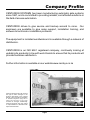
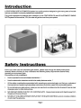
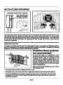
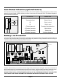
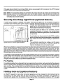
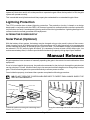
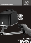
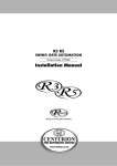
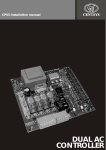
Table of Contents
Company Profile . . . . . . . . . . . . . . . . . . . . . . . . . . . . . . . . . . . . . . . . . . . . . . . . . . . . . . . . . . . . . . . . . . . 3
Introduction . . . . . . . . . . . . . . . . . . . . . . . . . . . . . . . . . . . . . . . . . . . . . . . . . . . . . . . . . . . . . . . . . . . . . . . 4
Safety Instructions. . . . . . . . . . . . . . . . . . . . . . . . . . . . . . . . . . . . . . . . . . . . . . . . . . . . . . . . . . . . . . . . . . 4
Principles of Operation . . . . . . . . . . . . . . . . . . . . . . . . . . . . . . . . . . . . . . . . . . . . . . . . . . . . . . . . . . . . . . 5
Features & Functions . . . . . . . . . . . . . . . . . . . . . . . . . . . . . . . . . . . . . . . . . . . . . . . . . . . . . . . . . . . . . . . 6
Introduction. . . . . . . . . . . . . . . . . . . . . . . . . . . . . . . . . . . . . . . . . . . . . . . . . . . . . . . . . . . . . . . . . . . . 6
Modes of Operation . . . . . . . . . . . . . . . . . . . . . . . . . . . . . . . . . . . . . . . . . . . . . . . . . . . . . . . . . . . . . 6
Standard Mode of Operation . . . . . . . . . . . . . . . . . . . . . . . . . . . . . . . . . . . . . . . . . . . . . . . . . . . 6
Radio Transmitter . . . . . . . . . . . . . . . . . . . . . . . . . . . . . . . . . . . . . . . . . . . . . . . . . . . . . . . . . 6
Intercom Pushbutton . . . . . . . . . . . . . . . . . . . . . . . . . . . . . . . . . . . . . . . . . . . . . . . . . . . . . . 7
Reversing Mode . . . . . . . . . . . . . . . . . . . . . . . . . . . . . . . . . . . . . . . . . . . . . . . . . . . . . . . . . . . . . 7
Condominium Mode. . . . . . . . . . . . . . . . . . . . . . . . . . . . . . . . . . . . . . . . . . . . . . . . . . . . . . . . . . 7
PIRAC Mode . . . . . . . . . . . . . . . . . . . . . . . . . . . . . . . . . . . . . . . . . . . . . . . . . . . . . . . . . . . . . . . . 7
Pedestrian Keyswitch (Optional) . . . . . . . . . . . . . . . . . . . . . . . . . . . . . . . . . . . . . . . . . . . . . . . . . . . 8
Anti-crushing Device. . . . . . . . . . . . . . . . . . . . . . . . . . . . . . . . . . . . . . . . . . . . . . . . . . . . . . . . . . . . . 8
Multiple Collision . . . . . . . . . . . . . . . . . . . . . . . . . . . . . . . . . . . . . . . . . . . . . . . . . . . . . . . . . . . . 9
Automatic Closing . . . . . . . . . . . . . . . . . . . . . . . . . . . . . . . . . . . . . . . . . . . . . . . . . . . . . . . . . . . . . . 9
Auto-close Override . . . . . . . . . . . . . . . . . . . . . . . . . . . . . . . . . . . . . . . . . . . . . . . . . . . . . . . . . 10
Protection Beam . . . . . . . . . . . . . . . . . . . . . . . . . . . . . . . . . . . . . . . . . . . . . . . . . . . . . . . . . . . . . . . 10
Gate Status Indication . . . . . . . . . . . . . . . . . . . . . . . . . . . . . . . . . . . . . . . . . . . . . . . . . . . . . . . . . 11
Battery Low Protection . . . . . . . . . . . . . . . . . . . . . . . . . . . . . . . . . . . . . . . . . . . . . . . . . . . . . . . . . . 11
Security (Courtesy) Light Timer . . . . . . . . . . . . . . . . . . . . . . . . . . . . . . . . . . . . . . . . . . . . . . . . . . . 12
Pre-flashing. . . . . . . . . . . . . . . . . . . . . . . . . . . . . . . . . . . . . . . . . . . . . . . . . . . . . . . . . . . . . . . . 12
Holiday Lock-out . . . . . . . . . . . . . . . . . . . . . . . . . . . . . . . . . . . . . . . . . . . . . . . . . . . . . . . . . . . . . . . 12
Lightning Protection . . . . . . . . . . . . . . . . . . . . . . . . . . . . . . . . . . . . . . . . . . . . . . . . . . . . . . . . . . . . 13
Alternative Power Supply . . . . . . . . . . . . . . . . . . . . . . . . . . . . . . . . . . . . . . . . . . . . . . . . . . . . . . . . 13
Solar Panel . . . . . . . . . . . . . . . . . . . . . . . . . . . . . . . . . . . . . . . . . . . . . . . . . . . . . . . . . . . . . . . . 13
Manual Release . . . . . . . . . . . . . . . . . . . . . . . . . . . . . . . . . . . . . . . . . . . . . . . . . . . . . . . . . . . . . . . . . . . 13
Basic Maintenance . . . . . . . . . . . . . . . . . . . . . . . . . . . . . . . . . . . . . . . . . . . . . . . . . . . . . . . . . . . . . . . . 16
Specifications . . . . . . . . . . . . . . . . . . . . . . . . . . . . . . . . . . . . . . . . . . . . . . . . . . . . . . . . . . . . . . . . . . . . 18
Troubleshooting Guide . . . . . . . . . . . . . . . . . . . . . . . . . . . . . . . . . . . . . . . . . . . . . . . . . . . . . . . . . . . . . 19
Product Guarantee . . . . . . . . . . . . . . . . . . . . . . . . . . . . . . . . . . . . . . . . . . . . . . . . . . . . . . . . . . . . . . . . 23
Page 2
Company Profile
CENTURION SYSTEMS has been manufacturing automatic gate systems
since 1987, and is committed to providing reliable, cost effective solutions in
the field of access automation.
CENTURION strives to give service and backup second to none. Our
engineers are available to give sales support, installation training, and
answers to technical or installation problems.
The equipment is installed worldwide and is available through a network of
distributors.
CENTURION is an ISO 9001 registered company, continually looking at
updating its products in line with world trends to ensure that its products will
provide customer satisfaction.
Further information is available on our website www.centsys.co.za
Centurion Systems (Pty) Ltd. reserves
the right to make changes to the
products described in this manual
without notice and without obligation
of Centurion Systems (Pty) Ltd. to
notify any persons of any such
revisions or changes. Additionally,
Centurion Systems (Pty) Ltd. makes
no representations or warranties with
respect to this manual.
Page 3
4. Be careful with moving parts and avoid close proximity to areas where fingers or hands could be
pinched.
5. Secure all easily accessed gate opener controls in order to prevent unauthorized use of the gate.
6. Keep the automated gate system properly maintained, and ensure that all working areas are free of
debris and other effects that could affect the gate operation and safety.
7. On a monthly basis, check the obstruction detection system and safety devices for correct operation.
8. All repair, and service work to this product must be done by a suitably qualified person.
9. This product was designed and built strictly for the use indicated in this documentation. Any other
use, not expressly indicated here, could compromise the good condition/operation of the product
an/or be a source of danger.
10. Centurion Systems does not accept any liability caused by improper use of the product, or for use
other than that for which the automated system was intended.
Principles of Operation
The CENTURION R3 and R5 rotary swing gate operators are both powered by a 12V DC motor using a
maintenance free, lead acid battery as the primary power source. The battery is charged via a 220V mains
supply or a solar panel. The major benefit of this philosophy is uninterrupted operation of the gates even
in the event of a mains power failure. For light industrial applications the R3 and R5 operators are both
available with a power-pack which can deliver the full current draw of the 12V DC motor. If battery back-up
is required, a battery is fitted in a separate enclosure. The capacity of the battery is determined according
to the number of operations required in the event of a power failure.
An independent motor drive unit operates each leaf of the gate. Both single and double leaf systems are
available. The MASTER operator and the SLAVE operator where applicable consist of a high torque
geared DC motor driving through a main reduction unit onto an output shaft. The output shaft is linked to
the gate via an articulated arm secured by a padlock. The drive units are self-locking preventing the gates
from being forced open.
The electronic controller, charger and maintenance free battery (7A/H) are housed inside the MASTER
motor of the system only. The electronic controller, which co-ordinates the operations of the drive units, is
further protected by a plastic enclosure inside the MASTER operator. For added reliability the controller is
fitted with advanced lightning protection based on circuitry, designed and tested in conjunction with the
CSIR.
The drive unit uses an innovative internal position control system with origin, to track the movement of the
gate and accurately set the "open" and "close" positions.
Each operator are fitted with an internal manual override release.
Page 5
Gate Status Indication (optional feature)
The controller can provide visual indication inside the house of the position of the gate and the condition of the
battery and power supply. A LED is typically mounted on the intercom inside the house. The different signals of
the LED are described below:
LEDSTATUS
STATUS
LED
INDICATION
INDICATION
Slow regular flash
Gate is opening
Fast regular flash
Gate is closing
Off
Gate is closed
On
Gate is open
1 Flash/2 seconds
Courtesy light latched on
2 Flashes/2 seconds
Mains failure
3 Flashes/2 seconds
Battery low
4 Flashes/2 seconds
Collision shutdown
Battery Low Protection
The controller has circuitry that monitors the state of the battery. During a power failure energy is drawn from the battery, but
not replaced. To protect the battery from being quickly damaged, the protection circuitry prevents the motors from being run
off the battery when the battery voltage drops below 10.6 volts.
CP75
L1
L2
(LED’s)
CHARGE
Status LED
TEST
(LED)
PSU
STD
RS232
STATUS
(LED)
SET
(LED’s)
SLAVE FUSE 16A S/B
MASTER
-BATT+
SLAVE
LIGHT
MASTER SENSOR
AUX FUSE 3A F/B
MASTER FUSE 16A S/B
LIGHT
FUSE
3A F/B
SS1 SS2 SS3 COM COM SOL 12V TRG IRB FRX LED PED LCK SET
Status LED location on the CP75 Controller Card
Indication that the battery low protection has been triggered is provided by the small gate status LED mounted on the
intercom inside the house, which will flash three times every two seconds . The gate system is shut off for at least one minute.
After this time the gate system can be reactivated but will shut off immediately again if a battery low condition persists.
CONTACT YOUR LOCAL GATE AUTOMATION SPECIALIST OR CENTURION SYSTEMS IF YOU DISCOVER
THAT THE BATT LOW SIGNAL GIVEN BY THE LED INSIDE THE HOUSE CONTINUES TO RE-OCCUR.
Page 11
system will shut down and it will not be possible to operate the gate. When the keyswitch is ON, the gate
system will operate normally.
This is an added security feature should the property be unattended for an extended length of time.
Lightning Protection
The CP75 controller has on-board lightning protection. The protection circuitry is based on a design
developed in conjunction with the CSIR. It is however important to realise that the controller's protection
only functions correctly if an adequate lightning earth is fitted during installation. Lightning damage is not
covered under the normal guarantee of the equipment.
ALTERNATIVE POWER SUPPLY
Solar Panel (Optional)
With the battery driven system, the battery may be charged using a solar panel in place of the conventional charging circuit. A 20 Watt panel will provide on average 10-12 daily operations of an average gate
without causing the battery to discharge over a period of time. (The allowable number of operations will
be reduced if 12V DC security lights are fitted). It is necessary to have at least a 35A/h deep cycle, low
maintenance battery fitted, in order to provide sufficient back-up capacity during days of poor weather
Manual Release
All gate operators have a means of manually operating the gate in the event of a total malfunction of the
equipment.
If one is locked outside the property, the padlocks connected to the clevis pin through the gate bracket
can be unlocked. This will allow the clevis pin to be removed and the linkage arm to swing away from the
gate. This will allow the gate to be opened sufficiently to allow a person to enter.
Once inside the property, to release either operator complete the following procedure:
NB: DO NOT OPEN THE COVERS WHEN EXPOSED TO DIRECT RAIN. ALWAYS SHIELD THE
UNIT WITH AN UMBRELLA.
Clevis Pin
Connecting Arm
Bush
Gate Bracket
Unlock the padlock securing the connecting arm.
Remove the clevis pin.
Swing the connecting arm to the side and open the
gate.
Page 13
To release the manual override, proceed as follows:
1.
2.
Unlock and remove the operator cover.
Allen Key
3.
Lift the controller housing fitted to a MASTER motor.
This is not necessary when releasing a SLAVE motor.
4.
Setup Tool
(DO NOT USE)
Swing open the manual release dust cover.
Insert the allen key provided into the manual release
mechanism and rotate it clockwise to release the
gearbox (approximately 12 turns)
Page 14
To re-engage the drive (disengage manual override):
5.
Unscrew the allen key (counter-clockwise) until the
top of the screw is flush with the top of the shaft.
6.
Rotate the dust cover back into position.
7.
Lower the controller housing into position (not
necessary for a SLAVE motor)
Allen Key
8.
Replace the operator cover and lock it in position.
Page 15
Basic Maintenance
The CENTURION system is designed to be maintenance free. However, there are some basic checks that
should be carried out regularly (every six months) which will increase the long term reliability of the
system, and prevent false triggering of the protection systems leading to erratic operation of the gate.
IMPORTANT: ISOLATE MAINS SUPPLY TO SYSTEM BEFORE CLEANING OR WORKING ON THE
EQUIPMENT. (NB: The battery driven operators will continue to operate due to the internal battery)
1. Remove all shrubs and vegetation which may
interfere with the motors or linkages.
2. Keep the inside of the motors and control
housings clear of insects and dirt.
3. Grease the gate hinges to ensure that the gate
swings freely.
4. Check that the padlocks can be opened. Apply
oil or grease to the padlocks, particularly during
the rainy seasons.
Page 16
Specifications
This is a basic checklist for your gate automation system. Should you experience a fault with the system,
R3
SPECIFICATION
220V AC ±10% 50Hz
Voltage (with CP84ER5V01 power supply unit)
120mA
AC Current draw (with CP84ER5V01 power supply unit)
DC Current draw (Max)
15A
Maximum solenoid lock current draw
2A
Output shaft rotational speed
3.5 rpm
Maximum output torque
140Nm
100*
Maximum number of operations per day (Average)
20
Maximum number of continuous operations
Typical time to open/close a gate
(For standard pedestal in recommended position)
10 seconds
±20
No. of operations on a 7A/H battery (should the mains power fail)
Sealed optical counter
with origin switch
Limit switches
Collision sensitivity
Electronic adjustable
Temperature range
-20 to +50 oC
Housing protection
IP55
Control card (single or double motor)
CP75
Corrosion protection (baseplate and arms)
Zinc electro galvanising
Maximum gate length & mass:
Gate Length:
Max. Allowable Leaf Mass:
1,5m
2,0m
2,5m#
3,0m#
3,5m#
1000kg
550kg
350kg
250kg
180kg
Max. wind speeds for which the operator will open the gate†:
For a 1.8m high gate, 25% coverage:
110km/h
82km/h
66km/h
55km/h
47km/h
For a 1.8m high gate, 100% coverage:
55km/h
41km/h
33km/h
27km/h
23km/h
*Subject to system power supply. Standard battery driven system with 7A/H battery is limited to 20 operations per
day.
# For pedestal mount installations where the gate exceeds 3m, and wall mount installations where the gate
exceeds 2,5m, it is recommended that an electric lock be fitted.
† This applies only to STANDARD pedestal mount installations installed according to the RECOMMENDED positions.
Page 18
Troubleshooting Guide
see if the symptom corresponds to any given in the list below. For each symptom listed, the probable
cause and action to be taken is given. In the event of the symptom not being listed, consult your installer
for assistance.
CAUTION
PRIOR TO WORKING INSIDE THE CONTROL CARD ENCLOSURE, ENSURE
THAT THE MAINS SUPPLY TO THE SYSTEM HAS BEEN ISOLATED.
NB: As this product is used outside of the control of the manufacturer, CENTURION SYSTEMS
(PTY) LTD, it cannot be held responsible for consequential damage as a result of the end user
attempting to maintain the unit without the assistance of a qualified installer.
SYMPTOM
CAUSE
ACTION
! Gate does not open or close
! There is an object obstruct-
fully or gate moves a short
distance and stops.
ing the movement of the gate.
! INDICATION: STATUS LED
will be flashing 4 times per 2
seconds.
! Anti-crushing device setting
is too sensitive
! Clear any obstructions from
the gate.
! Unhook the gate from the
mechanical linkage and
check that the motor operates
c o r r e c t l y. C o n s u l t y o u r
installer should there still be a
problem.
! Position control system is
malfunctioning.
! Check that the sensor
mounted adjacent the
geared DC motor is clipped
into position. Check both
MASTER and SLAVE motors
where applicable.
! Battery voltage is low and the
! INDICATION: STATUS LED
battery protection is being
activated.
will be flashing 3 times per 2
seconds.
! Check that the battery is
charging.
! Check that the mains supply
is connected and switched
on.
! Touch the side of the charger
unit, it should be hot if the
battery is charging.
! Check battery connections
are tight and that there is no
Page 19
SYMPTOM
CAUSE
ACTION
corrosion.
! When was the battery last
changed? †
† The life span of the 7A/H maintenance free battery supplied with the system is typically up to
three years.
! Gate does not operate but
the relays on the controller
"click" momentarily.
! Motor fuse blown on the
control card.
! Replace blown fuses R38 A m p s l o w b l o w. S i z e
5x20mm
! Make sure that the motor fuse
holders are making good
contact.
! Battery voltage is low.
! Gate lock not releasing
(applies to typically single
gate installations where a
solenoid or magnetic lock
has been fitted).
! See action earlier in this
troubleshooting guide for
battery voltage is low and the
battery low protection is
being activated.
! Solenoid lock: check that the
lock is trying to release. it will
make a distinctive "click"
sound when energised. Then
check that the lock is not
being mechanically held due
to misalignment, dirt etc.
! Magnetic lock: Pull on the
lock when activating the gate
to release and feel whenever
the lock is releasing. Try
disconnecting the lock
(remove the wire from
terminal 13)
! Consult your installer if the
problem persists.
! Gate does not operate and
there is no reaction from the
motor relays either. Only the
radio receiver relay "clicks"
when the system is activated.
! An input is latching up the
! Check that both the GREEN
IRB (infra red beam) and LCK
(holiday lockout) LED's on
the CP75 controller are ON.
controller.
! Check that the other RED
Page 20
SYMPTOM
CAUSE
ACTION
input LED's are OFF. They
must only light up when the
corresponding input is
activated.
! Try operating the system
using the TEST pushbutton
on the control card.
! Consult your installer if the
problem persists
! Gate does not auto-close.
! Infra red beam (if fitted) is
faulty.
! Check that the GREEN LED
adjacent the IRB input is ON
! When the IRB input is ON
! Then the infra red beam is
clear.
! Check that beam is correctly
aligned. It should be possible
to hear the relay "click" as the
beam is broken and cleared.
! Check that the auto-close
override facility is not being
operated.
! Gate starts closing but stops
and re-opens.
! Intermittent operation of infra
red beam if fitted.
! Ensure that nobody is
mistakenly pressing and
holding down the gate
release pushbutton on either
the remote or intercom for
too long when activating the
unit. Refer to section Autoclose override.
! Check the GREEN IRB LED
on the controller. It must
remain ON if the beam is
clear.
! Consult your installer if the
problem persists.
! Anti-crushing device is set
too sensitively.
! Operator drives too far and
does not stop in the correct
open and closed positions.
! Origin system not functioning
correctly.
! Unhook the gate from the
mechanical linkage and
check that the operator then
drives fully closed. Consult
your installer if the problem
persists.
! Check that the origin sensor
which is mounted on the
black plastic housing which
covers the manual override,
is properly clipped in.
Page 21
SYMPTOM
CAUSE
! Origin position has been
shifted.
! Gate opens on its own.
! Radio transmitter has poor
! Permanent input on one of
! Check that the RED LED's
the trigger lines to the
controller.
adjacent each trigger input
on the controller (TRG, FRX,
PED) are OFF and only
switch ON when that input is
activated.
! Consult your installer.
! Faulty trigger line cables.
! Transmitter battery flat.
range.
trian and closes.
! Courtesy light does not oper-
! Check that the fault only
receive transmitter signal
properly.
occurs with one of the
transmitters. Replace the
battery.
! Receiver must be mounted in
an elevated position, housed
i n a w e a t h e r p r o o f, n o n
ferrous enclosure.
! Make sure that the aerial is
straight.
! Consult your installer.
! Key-switch used for
! Check for corrosion of the
activating pedestrian facility
is faulty - where applicable.
wire terminations behind the
key-switch. Consult your
installer should the problem
persist.
! Radio receiver cannot
! Master gate opens to pedes-
ACTION
Consult your installer if the
problem persists.
! Make sure that nobody has
accidently used the origin
adjustment tool to release
the manual override. Consult
your installer should this be
suspected.
! Light fuse blown.
ate.
! Replace fuse - 220V 3A fast
blow. Size 5x20mm.
CAUTION - 220V, make
sure supply to system is
isolated
! Check that the lamp load
does not exceed 500W.
! Check the bulb and replace if
necessary. Make sure that
the bulb is making good
electrical contact in its
holder.
! Consult your installer should
the problem persist.
Page 22
Product Guarantee
All CENTURION products are manufactured with extreme care, thoroughly inspected and tested. They
are guaranteed for a period of 12 months, provided that proof of purchase documentation is submitted
with any claim.
The guarantee only covers repair, components and labour, provided that the equipment is returned to
our workshop.
This warrantee will not apply to any equipment which:
(A) Has been subject to misuse or which has been used for any purpose other than designed for by
the manufacturers.
(B) Has been repaired by any workshop and/or person not previously authorised by CENTURION
SYSTEMS.
(C) Has been repaired with components not previously tested, passed or authorised by
CENTURION SYSTEMS.
Page 23
CENTURION
THE AUTOMATIC CHOICE
CENTURION SYSTEMS (PTY) LTD HEAD OFFICE:
TEL: +27 (0)11 699-2400, FAX: +27 (0)11 704-3412 or 462-6669
148 EPSOM AVENUE, NORTH RIDING
P.O. BOX 506, CRAMERVIEW, 2060
SOUTH AFRICA
WEB: http://www.centsys.co.za
General information e-mail: [email protected]
FOR TECHNICAL SUPPORT CONTACT:
SOUTH AFRICA
EAST RAND. . . . . . . . . . . . . . . (011) 397-6401
DURBAN . . . . . . . . . . . . . . . . . (031) 701-9583
NELSPRUIT . . . . . . . . . . . . . . . (013) 752-8074/5
PRETORIA . . . . . . . . . . . . . . . . (012) 362-8819/8893
CAPE TOWN . . . . . . . . . . . . . . (021) 447-1295
PORT ELIZABETH. . . . . . . . . . . (041) 581-6994/5
EAST LONDON . . . . . . . . . . . . . . (043) 743-4923
BLOEMFONTEIN . . . . . . . . . . . . . (051) 448-1714
KIMBERLEY . . . . . . . . . . . . . . . . . (053) 832-3231
VEREENIGING . . . . . . . . . . . . . . . (016) 422-5667
AFRICA
ECHO-LINE, NAMIBIA . . . . . . . . . . . . . . . . . . . . . . . . . . . . . . . . . . . . . . . . . . . . . . . . . . . . . . . . . . . . . Tel: (61) 220-8309
MOLECULAR CONSULTANTS, NIGERIA . . . . . . . . . . . . . . . . . . . . . . . . . . . . . . . . . . . . . . . . . . . . . . . Tel: 803-3123182
SECURITY DISTRIBUTORS, ZIMBABWE . . . . . . . . . . . . . . . . . . . . . . . . . . . . . . . . . . . . . . . . . . . . . . . . Tel: (4) 795-873
SEKANYOLYA TIMBER WORKS, UGANDA. . . . . . . . . . . . . . . . . . . . . . . . . . . . . . . . . . . . . . . . . . . . . . . Tel: (41) 231-40
EUROPE
AUTOMATISME BATIMENT, FRANCE. . . . . . . . . . . . . . . . . . . . . . . . . . . . . . . . . . . . . . . . . . . . . . . . . Tel: (1) 697-93120
CROWN AXXESS LTD U.K. UNITED KINGDOM . . . . . . . . . . . . . . . . . . . . . . . . . . . . . . . . . . . . . . . . Tel: (1483) 450-011
NESTOR, BELGIUM . . . . . . . . . . . . . . . . . . . . . . . . . . . . . . . . . . . . . . . . . . . . . . . . . . . . . . . . . . . . . . . Tel: (9) 380-4020
NORTH AMERICA
BILLY GATES, CANADA . . . . . . . . . . . . . . . . . . . . . . . . . . . . . . . . . . . . . . . . . . . . . . . . . . . . . . . . . . Tel: (250) 334-1553
AUSTRALASIA
ABA GATES, WESTERN AUSTRALIA . . . . . . . . . . . . . . . . . . . . . . . . . . . . . . . . . . . . . . . . . . . . . . . . . Tel: (8) 933-03061
DOMINATOR SYSTEMS, NEW ZEALAND . . . . . . . . . . . . . . . . . . . . . . . . . . . . . . . . . . . . . . . . . . . . . . Tel: (3) 384-5145
ICBT, VICTORIA . . . . . . . . . . . . . . . . . . . . . . . . . . . . . . . . . . . . . . . . . . . . . . . . . . . . . . . . . . . . . . . . . . Tel: (3) 933-54213
ROTECH, QUEENSLAND . . . . . . . . . . . . . . . . . . . . . . . . . . . . . . . . . . . . . . . . . . . . . . . . . . . . . . . . . . Tel: (7) 326-47330
SA GATES, SOUTHERN AUSTRALIA . . . . . . . . . . . . . . . . . . . . . . . . . . . . . . . . . . . . . . . . . . . . . . . . . Tel: (8) 826-64235
SECURITE DU PACIFIQUE, NEW CALEDONIA . . . . . . . . . . . . . . . . . . . . . . . . . . . . . . . . . . . . . . . . . . . . . . Tel: 283-760
INDIAN OCEAN
SECULOGIX LTD, MAURITIUS . . . . . . . . . . . . . . . . . . . . . . . . . . . . . . . . . . . . . . . . . . . . . . . . . . . . . . . . . . Tel: 467-8509
SECURITE AUTOMATISMES REUNION, REUNION . . . . . . . . . . . . . . . . . . . . . . . . . . . . . . . . . . . . . . . . . . Tel: 280-368
ASIA & PACIFIC
VAST VIDEO, MALAYSIA . . . . . . . . . . . . . . . . . . . . . . . . . . . . . . . . . . . . . . . . . . . . . . . . . . . . . . . . . . . Tel: (3) 214-34931
BLT ASSOCIATES, THAILAND . . . . . . . . . . . . . . . . . . . . . . . . . . . . . . . . . . . . . . . . . . . . . . . . . . . . . . . Tel: (2) 691-6793