1
LATTICE Installation manual
NETWORKED
PROXIMITY ACCESS
CONTROL SYSTEM
Company Profile
Centurion Systems (Pty) Ltd, South Africa, has been manufacturing automatic gate systems since
1986, and is committed to providing reliable, cost effective solutions in the field of gate and access
automation.
We offer a diverse range of products including gate motors, GSM-based products, garage door
motors, remote controls, keypads, traffic barriers, proximity access control and intercom systems.
Our products are developed by an in-house team of talented engineers that are constantly
researching new and innovative technologies to improve our existing products and expand our
product range.
Our production facility in Johannesburg is ISO:9001 quality assurance certified, and all our products
are manufactured to the highest level of quality with a 100% test to specification.
Through a team of dedicated technicians and sales personnel, together with a fully fledged in-house
training facility, we are committed to providing unmatched service to our customers and support for
our products.
A worldwide network of distributors and installers ensure that our products remain The Automatic
Choice in access automation .
Further information is available on our website www.centsys.com.au
Centurion Systems (Pty) Ltd reserves the right to make changes to the products described in this document without notice and without
obligation of Centurion Systems (Pty) Ltd to notify any persons of any such revisions or changes. Additionally, Centurion Systems (Pty)
Ltd makes no representations or warranties with respect to this document.
No part of this document may be copied, stored in a retrieval system or transmitted in any form or by any means electronic,
mechanical, optical or photographic, without the express prior written consent of Centurion Systems (Pty) Ltd.
Page 2
Table of Contents
Company Profile . . . . . . . . . . . . . . . . . . . . . . . . . . . . . . . . . . . . . . . . . . . . . . . . . . . . . . . . . . . . . . . . . . . 2
Introduction . . . . . . . . . . . . . . . . . . . . . . . . . . . . . . . . . . . . . . . . . . . . . . . . . . . . . . . . . . . . . . . . . . . . . . . 4
What is Proximity Tag Technology. . . . . . . . . . . . . . . . . . . . . . . . . . . . . . . . . . . . . . . . . . . . . . . . . . . . . . 5
Specifications . . . . . . . . . . . . . . . . . . . . . . . . . . . . . . . . . . . . . . . . . . . . . . . . . . . . . . . . . . . . . . . . . . . . . 7
Tools & Equipment Required . . . . . . . . . . . . . . . . . . . . . . . . . . . . . . . . . . . . . . . . . . . . . . . . . . . . . . . . . 8
Installation of the Lattice Reader . . . . . . . . . . . . . . . . . . . . . . . . . . . . . . . . . . . . . . . . . . . . . . . . . . . . . . . 9
Installing the Lattice System . . . . . . . . . . . . . . . . . . . . . . . . . . . . . . . . . . . . . . . . . . . . . . . . . . . . . . . . . 12
Identification of Terminals . . . . . . . . . . . . . . . . . . . . . . . . . . . . . . . . . . . . . . . . . . . . . . . . . . . . . . . . 12
Summary of Possible Connections. . . . . . . . . . . . . . . . . . . . . . . . . . . . . . . . . . . . . . . . . . . . . . . . . 13
Take Up Head . . . . . . . . . . . . . . . . . . . . . . . . . . . . . . . . . . . . . . . . . . . . . . . . . . . . . . . . . . . . . . . . . 13
Wiring Diagrams . . . . . . . . . . . . . . . . . . . . . . . . . . . . . . . . . . . . . . . . . . . . . . . . . . . . . . . . . . . . . . . 14
Connection of Lattice Slave Heads (LSH). . . . . . . . . . . . . . . . . . . . . . . . . . . . . . . . . . . . . . . . . . . . 17
Setting the Lattice Slave Head Address . . . . . . . . . . . . . . . . . . . . . . . . . . . . . . . . . . . . . . . . . . . . . 19
Programming the Lattice System . . . . . . . . . . . . . . . . . . . . . . . . . . . . . . . . . . . . . . . . . . . . . . . . . . . . . 20
First Time Operation . . . . . . . . . . . . . . . . . . . . . . . . . . . . . . . . . . . . . . . . . . . . . . . . . . . . . . . . . . . . 20
Programming the System . . . . . . . . . . . . . . . . . . . . . . . . . . . . . . . . . . . . . . . . . . . . . . . . . . . . . . . . 20
Getting into Programming Mode . . . . . . . . . . . . . . . . . . . . . . . . . . . . . . . . . . . . . . . . . . . . . . . . . . 22
Basic Menu . . . . . . . . . . . . . . . . . . . . . . . . . . . . . . . . . . . . . . . . . . . . . . . . . . . . . . . . . . . . . . . . . . . 23
Quik Learn . . . . . . . . . . . . . . . . . . . . . . . . . . . . . . . . . . . . . . . . . . . . . . . . . . . . . . . . . . . . . . . . 23
Basic Learn . . . . . . . . . . . . . . . . . . . . . . . . . . . . . . . . . . . . . . . . . . . . . . . . . . . . . . . . . . . . . . . . 25
Basic Delete . . . . . . . . . . . . . . . . . . . . . . . . . . . . . . . . . . . . . . . . . . . . . . . . . . . . . . . . . . . . . . . 26
Basic Configure . . . . . . . . . . . . . . . . . . . . . . . . . . . . . . . . . . . . . . . . . . . . . . . . . . . . . . . . . . . . 27
Advanced Menu . . . . . . . . . . . . . . . . . . . . . . . . . . . . . . . . . . . . . . . . . . . . . . . . . . . . . . . . . . . . . . . 29
Quik Learn . . . . . . . . . . . . . . . . . . . . . . . . . . . . . . . . . . . . . . . . . . . . . . . . . . . . . . . . . . . . . . . . 29
Normal Learn . . . . . . . . . . . . . . . . . . . . . . . . . . . . . . . . . . . . . . . . . . . . . . . . . . . . . . . . . . . . . . 30
Delete Menu . . . . . . . . . . . . . . . . . . . . . . . . . . . . . . . . . . . . . . . . . . . . . . . . . . . . . . . . . . . . . . . 35
Installation Mounting Template . . . . . . . . . . . . . . . . . . . . . . . . . . . . can be found between 36 & 37
Configure Menu . . . . . . . . . . . . . . . . . . . . . . . . . . . . . . . . . . . . . . . . . . . . . . . . . . . . . . . . . . . . 38
Update Menu . . . . . . . . . . . . . . . . . . . . . . . . . . . . . . . . . . . . . . . . . . . . . . . . . . . . . . . . . . . . . . 47
Copy Menu . . . . . . . . . . . . . . . . . . . . . . . . . . . . . . . . . . . . . . . . . . . . . . . . . . . . . . . . . . . . . . . . 54
Template Menu . . . . . . . . . . . . . . . . . . . . . . . . . . . . . . . . . . . . . . . . . . . . . . . . . . . . . . . . . . . . . 57
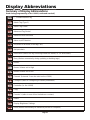
Display Abbreviations . . . . . . . . . . . . . . . . . . . . . . . . . . . . . . . . . . . . . . . . . . . . . . . . . . . . . . . . . . . . . . 62
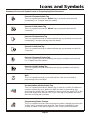
Icons and Symbols . . . . . . . . . . . . . . . . . . . . . . . . . . . . . . . . . . . . . . . . . . . . . . . . . . . . . . . . . . . . . . . . 65
Additional References . . . . . . . . . . . . . . . . . . . . . . . . . . . . . . . . . . . . . . . . . . . . . . . . . . . . . . . . . . . . . . 66
Revision History. . . . . . . . . . . . . . . . . . . . . . . . . . . . . . . . . . . . . . . . . . . . . . . . . . . . . . . . . . . . . . . . . . . 67
Installation Details . . . . . . . . . . . . . . . . . . . . . . . . . . . . . . . . . . . . . . . . . . . . . . . . . . . . . . . . . . . . . . . . . 68
Notes . . . . . . . . . . . . . . . . . . . . . . . . . . . . . . . . . . . . . . . . . . . . . . . . . . . . . . . . . . . . . . . . . . . . . . . . . . . 69
Page 3
Introduction
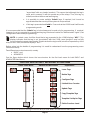
The Centurion Systems (Pty) Ltd Lattice system is a simple access control system with the ability to run in
both stand-alone and networked mode with up to 1000 tags.
The heart of the system comprises the L1000 Controller. This unit can operate as a stand-alone reader, or
as a controller in a networked system.
For added functionality the L1000 can be linked via a RS485 network to 31 additional reader heads known
as Lattice Slave Heads (LSHs).
In addition to the 31 LSHs there is also a Take Up Head (TUH) whose function is to link the RS485 network
to a computer (or computer network). The TUH is attached to the L1000 Controller via a communication
cable. The TUH also acts as a tag reader. The ideal position for the TUH is near the person maintaining
the system as new tags can be added and maintained easily.
The L1000 has a 3 digit, 7-segment LED display used with an “Admin” tag to programme the L1000 as
well as any LSH's linked to the system. The display brightness can be varied to suit ambient conditions.
Under normal running conditions the display of the L1000 will indicate the 3 digit ID number of the tag. A
buzzer also sounds momentarily to indicate that the tag has been read by the reader. The LSHs have a
simpler display comprising only three LEDs and a buzzer to indicate status. The buzzer can be configured to be silent.
Seven levels of anti-passback control are available in the networked version. Each reader is capable of
storing four separate counter values which decrement each time a valid tag is presented. This provides a
method of controlling how many times a person may use a particular asset (e.g. photostat machine,
sauna, etc).
Complex programming of the system can be done using only a single “Admin” tag, but a sophisticated
software system, called Lattice Ware (refer to page 66), is preferable as it provides an intuitive, graphical
user interface (GUI), via a connected laptop, or personal computer (PC). Lattice Ware provides sophisticated reporting as well as features and functionality not available without the computer. For example, if
the Lattice system is linked to an office network it is possible by means of a process known as “remoting”
to use networked computers to access certain functionality. A security guard could have a PC in his
guard house, and each time a tag is presented at the entrance, a photograph of the tag's correct owner
would flash up on his screen as confirmation that the tag is being used by the correct person. (For full
details, see the separate installation manual for the Lattice Ware software system).
The Lattice Ware system uses the freeware Firebird database which needs no license. Other databases
such as MySQL can also be used if required.
All of the readers operate on the new 13.56 MHz RFID norm which is likely to become the benchmark in
the future. This standard means tags are relatively inexpensive, give good read ranges and can offer,
optionally, read-write capability.
The Centurion Systems (Pty) Ltd Zap Tag is a perfect combination between a card and a tag. A label, with
photograph if required, can be fitted behind a plastic cover to provide tag identification.
Both flush and surface mount readers are available. The flush mount unit fits perfectly into a standard,
wall-mounted, light-switch box.
Page 4
What is Proximity Tag technology?
The word “proximity” means “close to” or “near”. Thus a tag has only to be brought “near” or within a
certain range of the reader before it is read. There is no physical contact between tag and reader. The read
distance is typically in the range 60 to 100 mm.
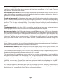
The system uses RFID (Radio Frequency IDentification) technology. The reader has an antenna which
sends out a weak radio signal. The tag also has an antenna (a small coil) that receives the reader signal
as soon as it is in range. The tag absorbs some of the energy from the reader signal and powers up the
electronic circuit on the tag. There is no battery in the tag and it is thus known as a “passive” tag. An
“active” tag has a battery and is used in applications requiring greater “read” ranges.
The electronics of the tag reads the unique serial number of the tag and transmits this serial number, back
to the reader.
The reader receives the signal and checks to see if the tag serial number is one that is stored within its
memory as a “valid” tag. If the tag is valid the reader operates a relay to unlock a door, open an automatic
gate, or switch on some device. Instead of tags one can also have credit card sized cards. The principle
of operation is identical. Centurion Systems (Pty) Ltd has concentrated on the passive plastic tag instead
of the card which is bigger and bulkier.
Basic concepts
Before describing the L1000 system in detail some basic terms and concepts are explained.
L1000 Controller: The “Master” controller in the system which can be used as a standalone reader head,
or can be interfaced with remote slave heads.
Lattice slave head (LSH): A Lattice slave head is an auxiliary head that must be networked to a L1000
Controller head using a RS 485 network. Up to 31 LSH's can be linked to a single L1000. A remote slave
head cannot operate as a stand alone head although it has the capability to respond to a maximum of 40
“supervisor” tags in an off-line situation.
Take up head: A tag reader which also creates the interface between the L1000 and a computer running
Lattice Ware software.
Site: A site is defined as the geographical area where the L1000 access control system is located. E.g.
Bryanston School, Durban Branch office, etc.
Network: A network is defined as a single L1000 and its TUH and LSH's.
Area: An area is a physical area in which personnel work, or into which, or through which, they move.
E.g. Sales area, passage, classroom, etc. It is possible to have infinite areas at a site, but access to only
16 can be effectively controlled with the L1000 system. (The L1000 has a maximum of 32 readers split
between 16 entrance, and 16 exit, readers)
Zone: A zone is defined as an area, (or areas), which form a security level (or hierarchy). Thus, it is
possible to move through several areas, but remain in the same zone. Only 7 different zones are allowed,
but each tag (or user) can have its own series of zones associated with it. Thus an entrance lobby,
passage and office 1 could be defined as zone 1 for user 1, whereas the entrance lobby and passage
could be zone 1 for user 2, and office 2 might be defined as zone 2. Anti-pass back levels (defined below)
operate between zones.
Page 5
Anti-pass back (APB): In general terms, this is a technique where a tag used at an “entrance” reader
cannot be re-used at that same entrance reader until it has been presented to an “exit” reader. Thus the
tag cannot be “passed back” to a friend!
Structured anti-pass back: Structured anti-pass back means that a reader will always check for the APB
status of the tag being presented, irrespective of whether the level is ascending or descending. Access is
granted only if all APB conditions are correctly met.
Freefall anti-pass back: Freefall anti-pass back means that APB will be checked by the reader only when
a user is moving from an area of low security to one of higher security level. If the user is effectively exiting
(i.e. going from higher to lower security level) the reader will permit exit without forcing a level by level
reduction. This is a type of free-exit facility. This provides for more flexibility of personnel movement
through various exit readers, but still provides the security that staff cannot gain access to unauthorized
areas.
Timed anti-pass back: In this form of APB, a user will be granted access to an area, but may not use the
same tag to gain access to the same reader until a specified time period has elapsed.
Anti-pass back levels: The L1000 system has up to seven APB levels per user. APB occurs at the reader
which is situated at the interface between one zone and another. The advantage of having multiple levels
is of particular use when a specific flow of personnel through a facility is required. E.g. In a hospital it may
be necessary for personnel to move first into a change room where dirty clothes are removed, then into a
'clean room” and then into an operating theatre. By defining the outside as zone 0, the change room as
zone 1, the clean-room as zone 2 and the theatre as zone 3, staff will be forced to move through the
hospital in a set sequence.
Limited uses counter: A counter into which a number can be entered and which decrements each time
that a valid tag is presented. Access will be prohibited when the counter reaches zero even if a valid tag is
presented. There are four limited uses counters that can be set-up.
ID (Identification number): The ID number is a convenient way to identify users, or groups of users, and
is used extensively during programming. A clear understanding of the ID concept is important.
The L1000 has provision to display 1000 ID's (000 to 999), limited by the 3 digit 7-segment display. One of
the attributes that is stored during the learn process is this ID number.
The reason for an ID is that although every single tag has a unique serial number it is not possible to
display this unique number on a 3 digit display. Thus, if a tag (or multiple tags for that matter) is allocated
an ID number, this provides a means to identify the tag (or series of tags).
It is preferable to have only one tag associated with each ID as this ensures that tags can be uniquely
identified. In some cases, however, there may be a requirement to allocate multiple tags to a single ID.
These IDs become not the ID of the individual people, but rather the group to which they belong.
E.g. it may be sufficient to allocate all sales staff (say five people) to ID=001, all factory workers (say 15
people) to ID=002, and all general staff (say 5 people) to ID=003. There are actually 25 tags being used,
but only three ID's, those being the Sales, Factory and General staff group.
Page 6
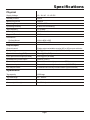
Specifications
Physical
Physical
Supply Voltage
10 - 12V AC 12-15V DC
Standby Current
50mA
Maximum Current
180mA
Operating Temperature
-20°C to 50°C
Operating Humidity
0-90% non condensing
Tag Frequency
13.56 MHz
Housing Material
ABS UV Stabilised
Degree of Protection
IP 55
Dimensions
Surface Mount
129H x 90W x 29D
Flush Mount
125H x 85W x 16D
Outputs/Inputs
Output channel
Single output selectable as relay (NC or NO) or open collector
Relay rating
50V @ 3A non inductive (N/C, COM, N/O)
Open collector rating (CHD)
50mA @24V (CHD)
Door open/forced output (ALARM)
50mA @24V (ALARM)
SmartSwitch II power output
200mA (CHD+)
Free-exit input
Potential-free normally-open contact (FRX)
Door sense input
Potential-free normally-closed contact (DOOR SEN)
Anti-tamper switch
Potential-free normally-closed contact (Optional extra)
Operational
Tag capacity
1000 tags
Tag read range
80 - 100mm
Alarm output time(s)
0 - 254 Adjustable in 1 second increments
Page 7
Tools and Equipment Required
Star Screwdriver
0 and 1 point
Long Nose Pliers
Flat Screwdriver
- 2.5mm point
Jewellers Type
Side Cutters
Tape Measure
ON
SILIC
Silicon
Cable: 0.20mm²
0.50mm²
0.75mm²
Level
5mm
Masonry Bit
Drilling Machine
(hammer action)
Multi-Meter
Page 8
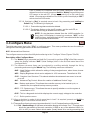
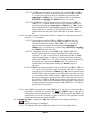
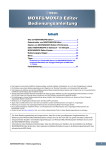
Installation of the Lattice Reader
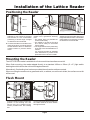
Positioning the Reader
1C
1B
1A
1100mm
300mm
320mm
pave
men
t
road
way
1300mm
!
!
1300mm
Position LATTICE reader on wall ! Alternatively mount the proximity ! Position the LATTICE reader on wall
reader onto a gooseneck ensuring adjacent to entrance gate. Mount at a
adjacent to door. Mount at a height
that:
height that allows for the comfortable
that allows for the comfortable
• The reader does not protrude too presentation of access tags. A height
presenting of access tags. A height
far into the driveway
of 1300mm is recommended.
of 1300mm is recommended.
• The reader is not set too far back
If a second reader is mounted on the
and cannot easily be accessed
inside of the door, it must be spaced
from a vehicle.
at least 300mm above or below the
• The height allows for the presenting
of the tag to be comfortable from a
outside reader to prevent interfevehicle.
rence.
An anti-knock shield is available
from CENTSYS to provide extra
protection to the LATTICE reader.
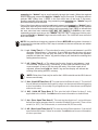
Mounting the Reader
The LATTICE Prox reader is available in a flush mount kit and a surface mount kit.
When flush mounting, the reader adapts directly to a standard 100mm x 50mm (4" x 2") light switch
backing box which allows the unit to sit flat against the wall.
Alternatively, if no backing box has been provided the unit can be surface mounted.
When mounting the reader onto a gooseneck with, or without, an anti-knock shield, the surface mount kit
will be used.
Flush Mount
1F
2
3
2F
100mm
! Insert the reader mounting frame into ! It is recommended that the cabling to
position in the backing box and
the reader extends at least 100mm
secure using the standard fixing
through the frame.
screws provided with the backing
box.
Page 9
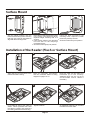
Surface Mount
1S
3S
2S
! Clip the plastic spacers onto the ! Place the mounting template located ! Using the slots provided in the
in the centre of this document at the mounting holes, adjust the reader
back of the mounting frame ensuring
required height ensuring that it is base to be perfectly vertical.
that they are correctly orientated to
vertical
align with the mounting holes.
! Using a 5mm masonry bit, drill holes ! Screw the frame firmly into position.
into the wall for the rawlplugs
provided in the kit.
! Screw the frame lightly into position.
Installation of the Reader (Flush or Surface Mount)
4
5
6
A
! Slide apart the front and back of the ! Make the necessary terminations ! Route the cable over the cable entry
bulkhead (A) in the housing.
onto the controller. Refer to wiring
reader controller housing.
Additional slots can be cut out to
diagram on pages 14-16.
accommodate further cables if
necessary.
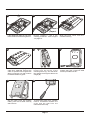
7
8
8
B Optional cable tie
B
! Fit a cable tie around the cable as ! Tighten cable tie.
shown. When tightened this holds
the cable in position and prevents it
from being pulled out of the housing.
Page 10
! An additional cable-tie can be fitted
to better secure the cable.
8B
9
B Optional cable tie 8 C
B
Jumper 2
Jumper 1
! If the additional cable tie was used, ! Ensure Jumpers 1 and 2 are ! Slide the back cover onto the
make certain that it is also tightened.
correctly positioned - refer to Figure controller housing.
1 on page 12.
10
11
A
12
B
! Ensure that it sits neatly against the ! Clip the top of the controller front ! Fasten controller housing into
position using the 2 x M4 pan head
housing into the top lip of the
cable entry bulkhead securing the
screws provided in the kit.
mounting frame (A), and fold down
cable. To prevent insect ingress use
into position ensuring the cable is not
either a grommet or a dab of silicon
caught (B).
to seal the cable entry point.
13
14
! Clip the outer cover into position ! To remove the outer cover, carefully
insert a screwdriver between the
making sure that it seats correctly
cover and the wall from the
and is secure.
underneath and unclip.
Page 11
Installing the Lattice System
The L1000 can be installed in three different configurations:
!
as a stand-alone head
!
as a stand-alone head, but linked to a computer via a Take Up Head (TUH)
!
as a fully networked system using up to 31 Lattice Slave Head (LSH's) and a TUH.
Before connections are made to the unit it is necessary to identify the terminals of the various units and
their functions.
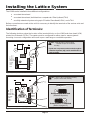
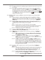
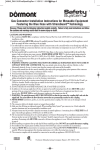
Identification of Terminals:
The following sketches show the location of the terminal blocks on the L1000 and slave head (LSH)
printed circuit boards (PCB's). The reader must be configured for either steel or masonry/wood
mounting. Incorrect configuration will result in poor read range or unreliable operation.
If pads are not present, unit must be brought to
Centurion Systems (Pty) Ltd for modification to
steel mounting.
LINK PADS
15 VDC
12 VAC
MAX
NB: Solder link pads for steel mounting.
Desolder link pads for wood/brick
mounting.
PC RX
PC TX
RS485C
RS485B
RS485A
N/C
COM
N/O
FRX-FIRE
DOOR SEN
ALARM
CHD +
CHD CHD
Fig 1 Layout of Lattice L1000 Controller
FRX-FIRE
DOOR SEN
ALARM
CHD +
CHD CHD
JUMPER 1
1 2 3 4 5 6
Jumper 1
JUMPER 2
ON
MAX
15 VDC
12 VAC
NB: Jumper 2 OFF for wood/brick mounting.
Jumper 2 ON for steel mounting.
Relay Output Enabled
(Standard Systems)
RS485C
RS485B
RS485A
N/C
COM
N/O
Smartswitch II Enabled
(Refer to pages 15)
Fig 2 Layout of Lattice SLAVE head
Page 12
NOTE: The 3 digit LED display of the L1000 is mounted on the reverse side of the PCB
As will be seen the terminals on the two different PCB's are virtually identical. The L1000 has an additional
two terminals (PC Rx and PC TX used to connect the L1000 to a Take Up Head) not found on the LSH. The
following table is a summary of all possible connections:
Summary of Possible Connections
Terminal
Reference
15 VDC
12 VAC
FRX-FIRE
DOOR SEN
ALARM
CHD+
CHDCHD
*PC RX
*PC TX
RS485C
RS485B
RS485A
N/C
COM
N/O
Description
Supply to the device can be AC, or DC, but must not exceed 15VDC or 12V AC
Free-exit (or Fire) normally-open, voltage free contact. Common connected to (CHD-)
Voltage free contact; closed when door is closed. Common connected to (CHD-)
External Alarm output (open collector).Positive connected to (CHD+).Maximum current 50mA
Smart Switch II positive (+12V DC)
Smart Switch II negative (system common terminal)
Smart Switch II drive (open collector)
Communication to take up head (Receive)(P2)
Communication to take up head (Transmit)(P1)
RS485 common
RS485 signal line B (twisted pair, CAT 5)
RS485 signal line A (twisted pair, CAT 5)
Output relay (normally-closed, voltage free)
Output relay (common, voltage free)
Output relay (normally-open, voltage free)
Table 1 showing Description of Terminal References
* - These terminals only on L1000, not LSH
Identification of the Take Up Head (TUH)
Network Proximity
Access Control
Take Up Head
Page 13
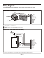
Wiring Diagrams
The following diagrams apply to both the L1000 Controller and the Lattice slave heads
(unless otherwise stated)
MAX
RED
BLK
CP84E PSU
EN
L
AC
Mains
12V
Batte
ry
15 VDC
12 VAC
Power Supply to L1000 or LSH
FRX-FIRE
DOOR SEN
ALARM
CHD +
CHD CHD
Fig 3 Power Supply to L1000 or LSH
NOTE: Polarity of the input voltage is not critical.
Free Exit, Door Contact and External Alarm Wiring
Alarm
Buzzer
Door Switch
(N/C Contact)
MAX
Free Exit
pushbutton
Maximum 50mA
(N/O)
FRX-FIRE
DOOR SEN
ALARM
CHD +
CHD CHD
Fig 4 Typical wiring for Free-Exit Pushbutton, Door Contact and External Alarm buzzer
Page 14
15 VDC
12 VAC
Entrance/exit
Door
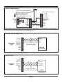
SMART Switch II Wiring
Secure free-exit pushbutton
These voltage free contacts
can be used to control
any external device
MAX
{
Centurion Systems (Pty) Ltd
SMART Switch II
COM
N/C
N/O
15 VDC
12 VAC
Secure free-exit wiring
FRX-FIRE
DOOR SEN
ALARM
CHD +
CHD CHD
Rx
Tx
FRX
GND
+12
NB: Lattice is not compatible with the standard SmartSwitch, a SmartSwitch II must be used!
Fig 5 Connection to Centurion Systems (Pty) Ltd SmartSwitch II
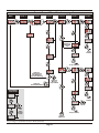
Wiring to Take Up Head (TUH)
Controller
L1000
PC RX
PC TX
RS485C
RS485B
RS485A
N/C
COM
N/O
Rx(P2)
Tx(P1)
COM
Twisted Pair Cable
(max 150 metres)
Take Up
Head (TUH)
Fig 6 Wiring from L1000 (only) to Take Up Head
Wiring to LSH
Controller
L1000
PC RX
PC TX
RS485C
RS485B
RS485A
N/C
COM
N/O
RS485C
RS485B
RS485A
Twisted Pair Cable
(max 1000 metres in total)
Fig 7 Wiring from L1000 to Lattice Slave Head
Page 15
Lattice
Slave Head
Magnetic Door Lock Wiring
RED
BLK
CP84E
PSU
Magnetic
Lock
EN
L
N
AC
Mains
PC RX
PC TX
RS485C
RS485B
RS485A
N/C
COM
N/O
S
12V
Batte
ry
NOTE: N/C and Com
Terminals used
Fig 8 Wiring to a magnetic type door lock
Solenoid Lock Wiring
RED
BLK
CP84E
PSU
EN
L
PC RX
PC TX
RS485C
RS485B
RS485A
N/C
COM
N/O
Solenoid
Lock
AC
Mains
SOL
*
SOL
12V
Batte
ry
* IN4007 or similar diode recommended
across coil to absorb inductive flyback
NOTE: N/O and Com
Terminals used
Fig 9 Wiring to a solenoid type door lock
Page 16
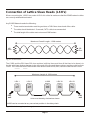
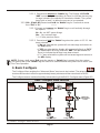
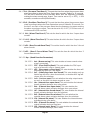
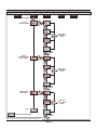
Connection of Lattice Slave Heads (LSH’s)
When connecting the L1000 to a series of LSH's it is critical to make sure that the RS485 network cables
are correctly wired and terminated.
Any RS485 Network needs the following:
!
There must be termination matching resistors of 100 Ohms at each end of the cable.
!
The cable should be twisted. Screened, CAT 5 cable is recommended
!
The total length of the cable must not exceed 1000 meters
Maximum Overall Length - 1000 metres
100
Ohm
100
Ohm
Fig 10 Twisted Cable
The L1000 and the RSH have 100 ohm resistors built into them and thus all that has to be done is to
decide which two devices happen to be at the end of the line and those resistors are then switched into
circuit. It is critical that ONLY the end two units have the end-of-line (EOL) resistors switched into circuit.
Maximum Length of 1000 metres
LSH 1
LSH 2
L1000
LSH 30
EOL
unit
LSH 31
EOL
unit
Units must be daisy chained as shown
L1000 can be mounted at any convenient position in the daisy chain.
Fig 11 Sketch showing daisy chaining of connected units
Page 17
The EOL switches on the L1000 and LSH's are located as shown in the sketches below:
Ensure jumper is
bridged if EOL resistor
needs to be
connected
PC RX
PC TX
RS485C
RS485B
RS485A
N/C
COM
N/O
Part of
L1000 PCB
12 3 4 5 6
ON
Fig 12 Part of L1000 showing jumper link that turns on EOL Resistor
Turn DIP switch 1 to
ON if EOL resistor
is required
PC RX
PC TX
RS485C
RS485B
RS485A
N/C
COM
N/O
Fig 13 Part of LSH showing dipswitch that turns on EOL resistor
Page 18
Part of
LSH PCB
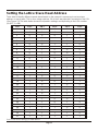
Setting the Lattice Slave Head Address
To be able to identify different remote slave heads on the network is necessary to set a unique
address on each head. This is done using switches 2-6 of the 6 way dipswitch mounted on the LSH.
(See Figure 13) The table below shows the dipswitch settings corresponding to the LSH number.
(0=OFF; 1=ON)
LSH
Sw 2
Sw 3
Sw 4
Sw 5
Sw 6
1
0
0
0
0
1
2
0
0
0
1
0
3
0
0
0
1
1
4
0
0
1
0
0
5
0
0
1
0
1
6
0
0
1
1
0
7
0
0
1
1
1
8
0
1
0
0
0
9
0
1
0
0
1
10
0
1
0
1
0
11
0
1
0
1
1
12
0
1
1
0
0
13
0
1
1
0
1
14
0
1
1
1
0
15
0
1
1
1
1
16
1
0
0
0
0
17
1
0
0
0
1
18
1
0
0
1
0
19
1
0
0
1
1
20
1
0
1
0
0
21
1
0
1
0
1
22
1
0
1
1
0
23
1
0
1
1
1
24
1
1
0
0
0
25
1
1
0
0
1
26
1
1
0
1
0
27
1
1
0
1
1
28
1
1
1
0
0
29
1
1
1
0
1
30
1
1
1
1
0
31
1
1
1
1
1
Table 2 DIP Switch Settings for LSH address
Page 19
Programming the Lattice System
First Time Operation
When the L1000 is powered up the display momentarily displays the firmware revision number.
Once powered up, the display flashes a single bar of the centre 7-segment display every 2 or 3 seconds
to indicate that the unit is in normal run mode. In a dark room it also acts as a means of locating the reader.
The display typically shows the following:
Present and remove any tag which is to be defined as the "Master" tag. This tag now becomes the
“Admin” tag. “Ad1” will be displayed to indicate that this “Admin” tag is being presented to the L1000
reader. It is possible to create multiple “Admin” tags as will be shown later.
Admin Tag (Type 1)
Any other “unlearned” tags presented to the system will display NIC (NOT IN CONTROLLER) as
follows:
Programming the System
The system can be completely programmed from the L1000 Controller using a single "Admin" tag and
the 3 digit, 7-segment LED display. (Incidentally, it is easier to programme, and more functionality is
provided, if the Lattice-Ware software is used. See separate, optional Lattice-Ware software).
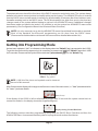
Fig 14
"Admin" tag
When the system comes from the factory there are no tags learned into memory. The first
tag presented becomes known as the “Admin” tag. This tag can be thought of as a type
of “master” tag, but it is termed the “Admin” tag due to the fact that system administration is done using this tag. Administration involves adding and deleting tags, modifying
reader settings, etc.
The "Admin" tag, shown in this documentation as a tag with a spanner symbol (See
Figure 14), has the following characteristics
!
The "Admin" tag is the "Master Key" to the system and must be looked after
carefully. Without it , programming cannot be done on the system.
!
The "Admin" tag is automatically learned into ID reference number 000
!
The first tag presented to a completely blank L1000 becomes the "Admin"
tag.
!
By default, when presented to the L1000 head the display will indicate "Ad1".
This is an indication that this tag has been learned into the system, but is not
Page 20
"associated" with any heads (readers). This means that although the tag is
valid, and in memory, it will not operate any of the relays. Thus, this tag, by
default, would not be a normal working tag.
!
It is possible to create multiple "Admin" tags, if required, but it must be
appreciated that the security of the system is compromised.
!
If this tag is presented and held for 5 seconds at the L1000 head it will invoke
programming mode.
It is recommended that the "Admin" tag is locked away and is used only for programming. If required,
however, it can be converted to a normal working tag, but where it retains its "Adminstration" rights. (See
configuration menu under programming).
NOTE: In certain cases it will be found that a tag presented to the L1000 displays “ASC”. This
display indicates that the tag is not "associated" with the L1000, even thought it may be fully
functional on the remote slave heads. To indicate that the tag is valid, but will not operate any of the
relays on the L1000, it therefore displays “ASC".
Before going into the details of programming it is useful to understand how the programming menu
structure is set-up.
Two different menu structures exist, namely
! BASIC, and
! ADVANCED
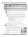
See the figure below which shows the tree structure for the first level menu for both BASIC and
ADVANCED Main Menus.
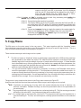
First Level Menu for BASIC and ADVANCED Main Menu
BASIC Main Menu
ADVANCED Main Menu
Explanation
Learn Tags
Delete Tags
Configure Tags
Limited Uses Counter
Update Tags
Copy/Template Tags
Template Set-Up for Tags
Exit to Previous Level
Fig 15 Tree Level Structure showing First Level Menu for both BASIC and ADVANCED Main Menu
Page 21
The advanced menu has all the functions of the BASIC menu plus a whole lot more. The system always
defaults to the basic menu structure to simplify setting up the system. The ADVANCED menu is invoked
from the BASIC menu and will remain in memory for approximately 20 minutes after it has last been used,
thereafter reverting back to the BASIC menu. The 20 minute period is to allow for a user to check out any
changes made to the system without having to get back into ADVANCED menu if additional changes
have been made and need to be tested. It is possible to set the system into ADVANCED menu mode
permanently. (See Configuration Menu in the Advanced Menu Structure)
NOTE: It is only necessary to go into the ADVANCED menu if specialised functionality is required.
Most of the standard run-of-the-mill programming can be done from the BASIC menu.
(Please see list of abbreviations at the end of this manual for a detailed abbreviation list).
Getting into Programming Mode
As has been indicated, “Ad1” is indicated on the display when the “Admin” tag is presented to the L1000.
To get into the first level of programming it is necessary to present and hold the “Admin” tag at the L1000
for 5 seconds. Please note the symbol below indicates “present and hold” for the "Admin" tag.
Fig 16 Present & Hold
"Admin" Tag symbol
NOTE: A full list of the icons and symbols used is shown at
the end of this manual.
After 5 seconds the display will change to the first menu item of the main menu, i.e. "Lrn" (the abbreviation
for "Learn") as shown below:
Lrn (Learn)
If the display of the L1000 is left un-refreshed for longer than 10 seconds the system reverts back to
normal run mode (i.e. the display shows the single flashing bar).
Display during Normal Run State
The following sections describe programming using firstly the BASIC Menu Structure and then the
ADVANCED Menu. It is assumed that the system is in program mode as described above.
Page 22
Basic Menu
The Basic Menu comprises the following sub-menu: • Lrn - Learn (Quik-Learn & Basic Learn)
• dEL - Delete
• CFg - Configure
• "---" - Exit to Previous Menu
Each of these menus is described in more detail below.
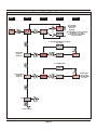
Basic Learn Menu
There are two learn mechanisms that exist under this menu. The first is QuikTM Learn which
automatically learns in a tag to all heads which are active on the RS485 bus at the time of learning
the tag. The second learn method enables tags to be learnt into specific Id's and into specific
heads.
1.
QuikTM Learn
The QUIKTM learn feature enables new tags to be entered very quickly into the system. The
flow diagram below shows the QUIKTM Learn Procedure and is described fully below:
QuikTM Learn
Icon
No
At this stage the system is ready to
have new tags learned in
1
2
3
4
5a
5b
Tag 1 has now been learned into ID
Number 001
6
7a
7b
Tag 2 has now been learned in, etc, etc.
Description of QUIK TM Learn procedure shown above
1
The display "Ad1" indicates that the system is in normal RUN mode and that a
correct Admin tag is being presented. The system cannot be programmed if any
tag other than the Admin tag is presented.
2
Present and Hold the Admin tag for 5 seconds.
3
The display changes to "Lrn" to indicate the system is in Learn mode.
4
Present and remove the first new tag to be learnt into the system.
5a On presentation of the first tag the display indicates the ID number into which this
tag has been learned. Eg. 001
5b On removal of the tag the display reverts back to "Lrn" indicating that the next tag
can be learned.
Page 23
Description of QUIK
TM
Learn procedure continued from previous page
6
Present and remove the second tag to be learned.
7a
On presentation of the second tag the display indicates the ID number into which
this tag has been learned. Eg. 002
7b
On removal of the tag the display reverts back to "Lrn" indicating that the next
tag can be learned.
Table 3. Quik TM Learn Description
NOTE:
! If tags are numbered make sure they are presented to the L1000 in the correct
order.
! When first used, the ID number starts at 001 if the QUIK learn feature is invoked.
If tags already exist in memory, then Quick learn will start from the next available
ID number.
! The QUIK learn feature will set factory defaults only, and none of the advanced
! functionality will be learned. Thus tags will have the following basic functionality:
! Tags are learned, automatically, into any LSH active on the system at the
time of programming.
! Tags will operate the main relay on the L1000 and LSH's.
! There is no anti-pass back.
! No limited uses counters are set.
! Relay 1 of the L1000 will operate by default for a 3 second pulse.
There is an alternative way to enter new tags which provides the ability
to set all the attributes for a tag. The menu structure is shown in Figures 21 and 22.
NOTE: The "ID Selection" symbol (Figure 17) appears in various levels of the menus
described hereafter. This symbol indicates:
! the display will count up or down as the "Admin" tag is presented and removed.
! if the green LED is ON, then the count increases as the tag is presented.
! If the red LED is ON, then the count decreases as the tag is
presented.
! the red and green LED's alternate if a tag is not presented.
! if the tag is presented and held in place, then the count rate
increases radically.
This same process applied to setting relay times (See Configure
Menu on page 38)
Fig 17
"ID Selection" symbol
Page 24
1.2. Basic Learn:
The Basic learn process is described below with reference to the "Basic" Learn Menu
Structure diagram (See Figure 18).
1.2.1. Present and hold the "Admin" Tag for 5 seconds to move from LRN of the main
menu to "000" of Level 1.
1.2.2. Present and remove the "Admin" Tag in association with the Red and Green
LED's on the L1000 to scroll the ID Number up or down to the required ID Number
for the new tag which has to be learned in. (In this example 006)
1.2.3. Present and remove a new tag. The display will change to "Con" (Controller)
1.2.4. Present and remove the "Admin" tag to scroll vertically through the available
heads, "Con" and "H.01" to "H.31". Only heads currently active on the bus will be
displayed.
1.2.5. Once the required head in 1.2.4. is selected, present and remove the NEW tag
while monitoring the red and green LED on the L1000. Each time the tag is
removed the LEDs will toggle. If the Red LED is ON it means that the tag will not
operated on this head and if the Green LED is ON the tag will operate on this
head.
1.2.6. Confirm the setting decided upon in 1.2.5. above by repeatedly presenting
and removing the "Admin" tag to scroll vertically down to -A1.2.7 Present and hold the new tag for 5 seconds to save the new tag. The display
will momentarily flash"dNE" to indicate that the new tag has been saved. To
learn additional tags, or wait 10 seconds for the systems to time out.
NOTE: If the "Admin" tag is presented and held at -A- the system will exit to Lrn.
Basic "Learn" Menu Structure
Main
Level 1
Level 2
Level 3
Toggle LED to
associate tag
with the reader
(Grn=Yes
Red= No
Flashes
message
momentarily
Option 2:
Exit back to Main Menu
if the Admin Tag is used
Option 1:
Saves New tag
& returns to process
next tag
Fig 18 Basic "Learn" Menu Structure
Page 25
Option 3:
Return to
top o f Level 3
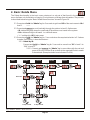
2. Basic Delete Menu
The Delete functionality in the basic menu structure is a sub-set of that found in the advanced
menu. It allows only for deletion of a tag by ID or bulk erase of all tags from all readers. The process
is described below using the "Basic Delete Menu Structure" shown in Figure 19.
2.1. Present and hold the "Admin" tag for 5 seconds to get from DEL of the main menu to ID of
level 1.
2.2. Present and remove to scroll vertically through the options in level 1. Options are:
• ID - deletes any tags stored in a particular ID location across heads in the system.
• ErA - deletes all tags in all heads. i.e. a full bulk erase.
• "---" - exit back to "dEL" main menu
2.3. Present and hold the "Admin" tag for 5 seconds when the required selection in 2.2 above
is made. Each option is described below: 2.3.1. Delete by ID.
Present and hold the "Admin" tag for 5 seconds to move from "ID" in level 1 to
"000" in level 2.
2.3.1.1. Present and remove the "Admin" tag in association with the red and
green LED's to scroll the ID up or down to the required ID which needs
to be deleted. (Example shown here indicates ID=014)
Basic "Delete" Menu Structure
Level 1
Main
Level 2
Level 3
Level 4
WAIT
Erase ALL
EXIT
to top of Level
to top of Level
Fig 19 Basic "Delete" Menu Structure
Page 26
2.3.1.2. Present and remove the "Admin" tag. The Display will FLASH
"dNE" momentarily (abbreviation for Done) to indicate that any tag
(or tags) stored in the selected ID have been deleted. The system
goes back to level 1 to allow the process to be repeated.
2.3.2. ErA - (Erase All) Present and hold the "Admin" tag for 5 seconds to move
from "ErA" to "No"
2.3.2.1. Present and remove the "Admin" tag to scroll vertically through
the options:
No - No, do NOT erase all tags.
Yes - Yes, erase all tags.
"---" - Exit to previous menu.
2.3.2.2. Present and hold the "Admin" tag when the option in 2.3.2.1. has
been selected.
• If No was selected the system will not erase tags and returns to
the ErA display.
• If YES was selected the display will momentarily flash up "bSY"
(an abbreviation for Busy) and then "dNE" (an abbreviation for
Done) to indicate that all tags have been erased.
• If "---" was selected the system will not erase tags and returns to
the dEL display.
NOTE: During a bulk erase (ErA) even the master or "Admin" tag is erased from the system.
This means that a new "Admin" tag will have to be created before the system can be used. (See
First Time Operation.
3. Basic Configure
The Configure Menu enables the "Advanced Menu" structure to be invoked. The advanced menu
structure will remain in effect for approximately twenty minutes and then revert back to BASIC.
The Configure menus are described fully below referring to the BASIC Configure menu (Figure 20)
Basic "Configure" Menu Structure
Main
Level 1
Level 2
select one
of the options
or exit
to top of Level
Fig 20 Basic "Configure" Menu Structure
Page 27
to top of Level
3.1. CFg - (Configure)
Present and hold the "Admin" tag to get from CFg of the main menu to AUS in level 1.
3.2. Present and remove the "Admin" tag to scroll vertically through level 1 to select the
options:
• AUS - Advanced User Structure
• "---" - Exit to Previous Menu
3.2.1. Present and remove the "Admin" tag to move from AUS of level 1 to ON in level 2.
3.2.2. Present and remove the "Admin" tag to scroll vertically through the following
options in level 2.
• On - Turns ON the Advanced User Structure
• OFF - Turns OFF the Advanced User Structure
• "---" - Exit to previous menu
3.2.3. Present and hold the "Admin" tag for 5 seconds when the required selection in 3.2.2
above has been made.
• If ON was selected the system displays CFg and it will be noticed that the full
ADVANCED menu structure will now be operational.
• If OFF was selected the system leaves the BASIC configure menu in place.
• If "---" was selected the systems exits back to the AUS Menu.
Page 28
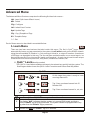
Advanced Menu
The Advanced Menu Structure comprises the following first level sub-menus: LrN - Learn (Quik-Learn & Basic Learn)
dEL - Delete
CFg - Configure
Ltd - Limited Uses Counter
Upd - Update Tags
CPy - Copy Template or Tags
tPL - Template Setup
"---" - Exit
Each of these menus is described in more detail below.
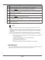
1. Learn Menu
There are two learn mechanisms that exist under this menu. The first is QuikTM Learn, which
automatically learns any tag presented to the system into all active heads on the RS485 network
using the next available ID number. i.e. Only one tag is linked to a unique ID number. A maximum
of 999 tags can be added in this way. The second learn method enables one or more tags to be
learned into specific IDs or into specific heads and if required, for each tag to have its own unique
characteristics such as anti-pass back, relay times, limited uses counters, etc.
1.1. Quik
TM
Learn(identity number)
TM
The QUICK learn feature enables new tags to be entered very quickly into the system. The
flow diagram below shows the QUIKTM Learn Procedure and is described fully below:
QuikTM Learn
Icon
No
At this stage the system is ready to have
new tags learned in
1
2
3
4
5a
5b
Tag 1 has now been learned into ID
Number 001
6
7a
7b
Tag 2 has now been learned in, etc, etc.
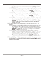
Description of QUIK TM Learn procedure shown above
1
The display "Ad1" indicates that the system is in normal RUN mode and that a
correct "Admin" tag is being presented. The system cannot be programmed if any
tag other than the"Admin" tag is presented.
2
Present and Hold the"Admin" tag for 5 seconds.
Page 29
Icon
No
Description of QUIK
TM
Learn procedure continued from previous page
3
The display changes to "Lrn" to indicate the system is in Learn mode.
4
Present and remove the first new tag to be learnt into the system.
5a
On presentation of the first tag the display indicates the ID number into which this
tag has been learned. Eg. 001
5b
On removal of the tag the display reverts back to "Lrn" indicating that the next tag
can be learned.
6
Present and remove the second tag to be learned.
7a
On presentation of the second tag the display indicates the ID number into which
this tag has been learned. Eg. 002
7b
On removal of the tag the display reverts back to "Lrn" indicating that the next
tag can be learned.
Table 4. Quik TM Learn Description
NOTE:
! If tags are numbered make sure they are presented to the L1000 in the correct
order.
! When first used, the ID number starts at 001 if the QUIK learn feature is invoked.
If tags already exist in memory, then Quick learn will start from the next available
ID number.
! The QUIK learn feature will set factory defaults only, and none of the advanced
! functionality will be learned. Thus tags will have the following basic functionality:
! Tags are learned, automatically, into any LSH active on the system at the
time of programming.
! Tags will operate the main relay on the L1000 and LSH's.
! There is no anti-pass back.
! No limited uses counters are set.
! Relay 1 of the L1000 will operate by default for a 3 second pulse.
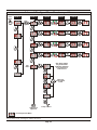
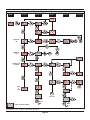
1.2. Normal Learn:
There is an alternative way to enter new tags which provides the ability to set all the
attributes for a tag. The menu structure is shown in Figures 21 and 22.
Page 30
Using the "Normal Learn Menu Structure" as a guide, the following steps are followed
fo Normal Learn.
1.2.1. The “Admin” tag is presented and held (for 5 seconds) to get from “Lrn” of the
Main menu to where the display indicates “000”. i.e from the Main menu to
Level 1.
1.2.2. The “Admin” tag is again presented and removed to get the display to increase, or
decrease, (as described above) until the required ID is reached. (Level 1 to Level
2)
1.2.3. A “new” tag is now presented which moves the display from level 2 to level 3. The
change from level 2 to level 3 is shown by the fact that the ID shown as numeral
"026" in this example, changes to “Con” (abbreviation for Controller). This
indicates that the system will now allow any of the configuration options of levels
4, and onwards, to be set up on the L1000 reader. Two routes can now be
followed:
1.2.3.1. If the “Admin” tag is presented and removed, the display will scroll
vertically through the list showing any connected readers, indicated as
“Con” (for the L1000 Controller) and “H.01” to “H.031” (for any LSH's
physically attached to the RS485 network). This enables the settings of
levels 4 and onwards to be set individually on any attached reader.
After the last attached head is shown the display indicates -A-. This is
the display symbol to indicate SAVE or EXIT. Once “Con” and,
optionally, heads H.01 to H.31 are set, it is critical that -A- is selected
(present and hold the “NEW” tag) to save all the settings that may have
been made to levels 4 onwards to all the readers.
NOTE: If the "Admin" tag is presented at -A- the system will exit
back to the main menu without saving any changes.
1.2.3.2.. Once a reader is selected (as per 1.2.3.1. above), the display is moved
from level 3 to level 4 by presenting and holding the “Admin” tag. e.g.
if “Con” is displayed and the “Admin” tag is presented and held (for at
least 5 seconds) the display will change from “Con” to “ASC”.
1.2.4. Similar to level 3 it is possible to scroll vertically through the “ASC” (associations), “APb” (anti-pass back), “Ltd” (Limited uses counters), “OLA” (Off-Line
Access), or “- - -” (Exit back to previous level) by presenting and removing
the “Admin” tag. Once a specific menu item in level 4 is decided upon, the
display is moved, horizontally, from level 4 to level 5 by presenting and
holding the “Admin” tag for 5 seconds. E.g. if “ASC” is displayed and the
“Admin” tag is presented and held for 5 seconds then the display changes
from “ASC” to “CH.1”
NOTE: The OLA Menu will only appear for LSH's. It does not apply to the
L1000.
1.2.5. The various options presented in level 5 depend on what was selected in level
4. For example:
1.2.5.1. If "ASC" was selected then channel 1 or 2 (only channel 1 can be selected
for LSH's) is first chosen by scrolling vertically through Ch.1, Ch.2, or "---" if
exit to a previous level is required), by presenting and removing the “Admin”
Page 31
tag. The resultant choice is selected by presenting and holding the “Admin”
tag for 5 seconds.
1.2.5.2. If "APb" was selected then an anti-pass back level L.01 to L.07 is first chosen
by scrolling vertically through the levels L.01 to L.07, or "---" if exit to a
previous menu is required) by presenting and removing the “Admin” tag.
The resultant choice is selected by presenting and holding the “Admin” tag
for 5 seconds.
1.2.5.3. If “Ltd” was selected then a limited use counter C.01 to C.04 is first chosen
by scrolling vertically through the list C.01 to C.04, or "---" if exit to the
previous level is required) by presenting and removing the “Admin” tag.
The resultant choice is selected by presenting and holding the “Admin” tag
for 5 seconds.
1.2.5.4. If “OLA” was selected (applies only to a LSH) then the “No” or “Yes”, or "---"
(if exit to the previous level is required) selection is made by presenting and
removing the “Admin” tag. ”No” means that the head will NOT allow a tag
to operate at the LSH when the head is off line (i.e. not linked via the RS485
network). “Yes” specifies that the head will permit valid “OLA” tags to
operate, even off-line.
1.2.6. The various options in level 6 depend again on what was selected in level 5. For
example.
1.2.6.1. Depending on whether CH.1 or CH.2 was selected then its associated relay
can be set to be “On” or “OFF” by scrolling vertically through the options
”On”, “OFF”, or “---” if exit to a previous level is required) by presenting and
removing the “Admin” tag. The selection is confirmed by presenting and
holding the “Admin” tag for 5 seconds.
1.2.6.2. Depending on which of the “APb” levels L.01 to L.07 was previously
selected, the choice of whether this reader is at the “entrance” or “exit” to an
APB zone, defined by the “In” or “Out” selection respectively, is made by
scrolling vertically through the options “In”, “Out”, or “---” (if exit to a
previous level is required) by presenting and removing the “Admin” tag.
The selection is confirmed by presenting and holding the “Admin” tag for 5
seconds.
1.2.7. Once the attributes of “Con” and, optionally, heads H.01 to H.31 are set, it is critical
that -A- in level 3 (see section 1.2.3.1.) is selected (i.e. present and hold the new
tag presented in 1.2.3 ) to save all the settings that may have been made to levels 4
onwards to all the readers.
Page 32
Normal "Learn" Menu Structure - page 1
Main
Level 1
Level 2
Level 3
Level 4
Level 5
Level 6
Eg.
ID Number=026
Channel 2
applies to
Controller
only
to top
of Menu
to top of Menu
Option 1:
Save New Tag
and Return to
Process Next Tag
Option 3:
Move to
top of Menu
Option 2:
Exit to Main Menu
Remember!
Last Level
to top
of Menu
select
one
of the
options
or exit
A
refer to
Figure 22
Fig 21 Page 1 of Normal "Learn" Menu Structure
Page 33
to top of Menu
Normal "Learn" Menu Structure - page 2
Main
Level 1
Level ...
Level 4
Level 5
A
from previous
page (Figure 21)
Level 6
Select Limited
Uses Counters
select
one
of the
options
or exit
to top of Level
to top of LTD
Menu in
Level 5
Select
Off-Line
Association
select one
of the options
or exit
Only
displayed
for heads
H.01 to H.31
Exit
to top of OLA
Menu in
Level 5
to top of
Level 4
Fig 22 Page2 of Normal "Learn" Menu Structure
Page 34
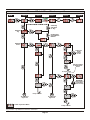
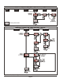
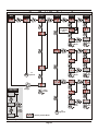
2. Delete Menu
The second main menu item is "dEL" which allows for deletion of tags.
Deletion of tags can be done by ID, by actual physical tag, by tags specific to certain readers (heads), or by
doing a bulk erase of all tags in the system.
Using the Advanced Delete Menu Structure (shown in Figure 23 and 24) as a guide the following steps are
followed:
2.1. The “Admin” tag is presented and held (for 5 seconds) to get from “dEL” of the “Main” menu to
where the display indicates “ID”. i.e from the Main menu to Level 1.
2.2.Decide on how tags are to be deleted as follows:
2.2.1. Present and remove the "Admin" tag to scroll the display vertically, allowing deletion of
tags by either
• Id - (Identity number)
• tAg - (specific physical tag)
• Hd - (tags associated with a specific head)
• ErA - (erase all, or bulk erase)
• "---" - (exit back to previous level
2.2.2. Once a decision is made of how tags are to be deleted in 2.2.1 above then the “Admin”
tag is presented and held for 5 seconds to move from level 1 to level 2.
2.3. The specifics of each different deletion mechanism (selected in 2.1.1 above) is described
more fully below:
2.3.1. Delete by “Id”. If delete by ID was selected then the display will be indicating ID number
“000”.
2.3.1.1. Select the required ID by presenting and removing the “Admin” tag to increase
(or decrease) the ID (see details of ID selection symbol described previously)
2.3.1.2. When the correct ID is selected, WAIT.
2.3.1.3. When the display changes to "SEt", present and remove the "Admin" tag. If
successful the display will flash "dnE" and return to "Id" to allow selection of
another ID to be deleted.
2.3.2. Delete by “tAg”. If delete by "tAG" was selected then the display will look as follows.
2.3.2.1. Present the tag to be deleted.
2.3.2.2. The display momentarily flashes up “dnE” (done) indicating the tag has been
successfully deleted. If a tag already deleted, (i.e. not stored in memory), is
presented the display will indicate “…” (not in memory)
2.3.2.3. The display reverts to
after successful tag deletion. If the “Admin” tag is
presented the system exits the tag deletion menu and the display reverts to
“tAg”.
2.3.3. Delete by “Hd". If delete by "Hd" was selected then the display will be indicating "Con"
(Controller).
2.3.3.1. Select the head (i.e. Reader) from which tags need to be removed by scrolling
vertically through the attached heads, “Con” and any RLSH’s shown as H.01 to
H.31 (only those linked at the time will display).
Page 35
Advanced "Delete" Menu Structure - part 1
Level 1
Main
Level 2
Level 4
Level 3
Level 5
WAIT
Admin tag
exits back
to "tAg:
Delete by
Tag
Existing tags
presented are
deleted
Delete by
Head
select one
of the
options
or exit
Only ID's linked
to head will be
listed
to top of Level
WARNING!
This action is
irreversible.
(See 3.3.5.3)
n
A
B
to top of Menu
To next page
Figure 24
To next page
Figure 24
= EXIT to previous Menu
n
to top of Menu
Fig 23 Part 1 of Advanced "Delete" Structure
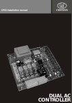
Page 36
DRILL 5mm
CONDUIT
LOCATION
CONDUIT
LOCATION
3
3
NOT
RECOMMENDED
NOT
RECOMMENDED
DO NOT ALLOW
CABLE ACCESS
THROUGH
THIS AREA
PREFERRED
CONDUIT
LOCATION
PREFERRED
CONDUIT
LOCATION
2
1
DRILL 5mm
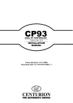
SURFACE MOUNT INSTALLATION
This mounting template is to be used when
performing a surface mount installation.
! When planning where to locate the unit, it is
important to consider the cable entry position. Do
not allow cables to enter the unit through the centre
area as this will interfere with assembly of the unit
after installation.
! Place the template in such a manner that conduit,
where provided, will be behind one of the four
preferred conduit locations shown alongside. If
conduit is not provided, surface mounted cabling
should be planned to enter the unit through one of
the four preferred locations indicated.
! The conduit locations are indicated in order of
preference. Location 1 being the most preferable
cable entry location and location 3 being the least
preferable cable entry location.
MOUNTING TEMPLATE
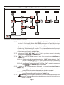
Advanced "Delete" Menu Structure - part 2
Level
Main1
Level 2
Level 3
A
Level 4
Level 5
B
n
= EXIT to previous Menu
Fig 24 Part 2 of Advanced "Delete" Structure
2.3.3.2. Once the head is selected, present and hold the “Admin” tag to move from level
2 to level 3 . Display will indicate “ALL” (Delete all tags in this head). At this stage
there are a number of different ways in which the tags can be deleted. Viz:
• Delete all tags in the head selected by selecting “ALL”
• Delete tags in this head by ID number. The system will automatically prompt
the user with only those Id’s actually stored in this head.
• Delete tags using specific available tags.
2.3.3.3. Selection of “ALL”, "Id”, “tAg”, or “---” (exit to previous menu) is done by
presenting and removing the “Admin” tag.
2.3.3.4. If “ALL” tags must be deleted move to level 4 by presenting and holding the
“Admin” tag.
2.3.3.4.1. Rotate vertically through the selections “yES” (delete all tags), “No”
(do NOT delete all tags), or “---” (exit to previous menu) by presenting
and removing the “Admin” tag.
2.3.3.4.2. Confirmation of the selection of “yES” or “No” is made by presenting
and holding the “Admin” tag for 5 seconds.
2.3.3.5. If delete by “Id” is required move to level 4 by presenting and holding the
“Admin” tag.
2.3.3.5.1. The display will indicate the lowest ID number stored in this head. The
green LED in the centre of the reader will also be illuminated.
2.3.3.5.2 Scrolling vertically through the list of all Id’s stored in the head can be
done by presenting and removing the “Admin” tag.
2.3.3.5.3.
Warning: Once the step described below is performed the delete process cannot be
reversed. The tag would have to be re-learned (or associated with this head) for it to
be seen as a valid tag.
Page 37
If an ID needs to be deleted from this head (remember it will not be
deleted from other heads) present and hold the “Admin” tag until the green
LED swops to the red LED. All tags stored under this ID on this head are now
deleted. If these tags were deleted from the L1000 they will in future display as “ASC”
and not show their old ID number.
2.3.3.6. If delete by “tAg” is required move to level 4 by presenting and holding the
“Admin” tag. The following is displayed
2.3.3.6.1. Present the tag that needs to be deleted.
2.3.3.6.2. The display flashes up the tag ID number, and the red LED, to
indicate that the tag is deleted from this head.
NOTE: If a tag has been deleted from the L1000 controller (i.e.
Con), then it will display in normal run mode as “ASC” on the
L1000 in future, indicating that it is NOT associated with this head.
It will still operate at other heads.
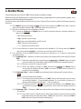
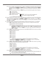
3. Configure Menu
The third main menu item is the “CFg” or configure menu. This menu provides the user the ability to
configure the following parameters on the various readers:
AUS - Advanced User Structure
The configure menus are described fully below referring to the “Configure” Menu (Figures 25 to 28)
Description of the Configure Menu
3.1. The “Admin” tag is presented and held (for 5 seconds) to get from “CFg” of the Main menu to
where the display indicates “HdS” (Head Settings) which is the first sub-menu item of the
Configure Menu.
3.2. The various sub-menu items can be selected by scrolling vertically through the list by
presenting and removing the “Admin” tag. The following menus are selectable.
•HdS - Head Settings which allows for setting of relay energise timers, alarm timers, buzzer
volume, etc.
• dSP - Display Brightness which can be adjusted in 10% increments. The default is 50%
• CUS - Complex User Structure. This selects whether the advanced user menu is turned
on or off.
• AtC - Advanced Tag Control. Allows for creation of additional “Admin” tags.
• bnr - Backup and restore. This allows the controller memory to be backed up to, or
restored frm, the optional backup memory module.
• PCS - P.C. System menu. This allows the user to specify whether or not the system is
connected to a P.C.
• SUP - This is a diagnostic tool which displays the current supply voltage to the controller.
• "---" - Exit to previous menu
3.3. Once a decision is made of which menu item in level 1 is required, present and hold the
“Admin” tag for 5 seconds to move to level 2.
3.4. The specifics of each sub-menu item described in 2.1 to 2.5 is described more fully below.
3.4.1. Hd - (Head settings): If HdS was selected the display will indicate “Con”. This sub-menu
allows the parameters of the main controller (L1000) or any of the attached LSH’s (i.e.
H.01 to H31) to reset. Select which reader (head) needs to be set by presenting and
Page 38
removing the “Admin” tag to scroll vertically through the heads. When the required
head is displayed, present and hold the “Admin” tag for 5 second. The display will then
indicate “rt1” (Relay time 1) which is the first menu item of the level 3 sub-menu.
Scrolling vertically through level 3 by presenting and removing the “Admin” tag will
allow the following to be selected.
If any of the timers below need to be adjusted, present and remove the “Admin” tag in
conjunction with the green and red LED to scroll the count up and down to the required
value. Wait a few seconds and the display will momentarily flash “SEt” to indicate that
the new value has been selected, BUT NOT YET SAVED! To SAVE the new value,
repeatedly present and remove the “Admin” tag until “-A-” is displayed. At this point,
preset and hold the “Admin” tag to save the new value. The L1000 will now return the
level 2 sub-menu.
NOTE: It is possible to change any number of timers BEFORE saving them. However, it
is important to note that until the “-A-” step is carried out, the new values are not written
to the memory.
3.4.1.1 ryt - Relay Time 1. i.e. The pulse time for relay 1 can be set between 1 and 254
seconds. (Default time = 3 seconds). If set to 000 seconds the relay will never
energise. (If set to 255 the relay will latch). If the time needs to be adjusted,
present and hold the “Admin” tag and the display will indicate the existing time
setting stored in memory.
3.4.1.2. rt2 - Relay Time 2. i.e. The pulse time for relay 2 can be set between 1 and
254 seconds. (Default time = 3 seconds). If set to 000 seconds the relay will
never energise. (If set to 255 the relay will latch). If the time needs to be
adjusted, present and hold the “Admin” tag and the display will indicate the
existing time setting stored in memory.
NOTE: Relay time 2 can only be set for the L1000 controller as the LSH’s do not
have a second relay.
3.4.1.3. Hot - (Hold Off Timer Door 1) This sets the hold off time for door 1. The hold off
time is defined as the time during which a door can be opened without triggering
a door foced alarm. It is usually only of significance in cases where a pre0impilse
strike lock is used.
3.4.1.4. Ht2 - (Hold Off Timer Door 2) This sets the hold off timer for door 2 (only
applicable to the L1000). See Hot above for more information on hold off time.
3.4.1.5. dot - (Door Open Time Door 1) This sets the time that door 1 can be left open
before the buzzer prewarn alarm is sounded (Default 10 seconds). Time can be
set at 0 (i.e. OFF), 1 to 254 seconds, or continuous ON (255 seconds)
3.4.1.6. dt2 - (Door Open Time door 2) This sets the hold off time that door 2 can be left
open before the buzzer ? Alarm is sounded. See dOt above for more information
on door open time.
Page 39
3.4.1.7.Prt - (Pre-warn Time Door 1) This sets the time from when the pre-warn alarm
starts sounding to where the Door Open alarm sounds. Default is 15 seconds.
For the last 5 seconds of the pre-warn alarm time the frequency increases
making the alarm sound more urgent. Time can be set to 0 (i.e. OFF), 1- 254
seconds, or continuous ON (255 seconds)
3.4.1.8.Pr2 - (Pre-Warn Time Door 2) This sets the time from when the pre-warn alarm
starts sounding to where the Door Open alarm sound. Default is 15 seconds. For
the last 5 seconds of the pre-warn alarm time the frequency increases making
the alarm sound more urgent. Time can be set to 0 (i.e. OFF), 1-254 seconds, or
continuous ON (255 seconds)
3.4.1.9. ALt - (Alarm Time Door 1) This sets the time for which the door 1 open alarm
sounds.
3.4.1.10. AL2 - (Alarm Time Door 2) This sets the time for which the door 2 open alarm
sounds.
3.4.1.11.dFt - (Door Forced Alarm Time) This set the time for which the door 1 forced
alarm sounds.
3.4.1.12.dF2 - (Door 2 Forced Alarm Time) This sets the time for which the door 2
forced alarm sounds.
3.4.1.13. Hrp - (Head Reaction Parameters)
3.4.1.13.1
bot - (Buzzer on tag) This sets whether a buzzer sounds when
a tag is presented.
3.4.1.13.2 FFP - (Free-Exit/Fire/Panic) This sets whether the FRX input
acts as a free-exit, a fire or a panic input.
3.4.1.13.3 dFS - (Door open on fire signal) This sets whether the door will
automatically open on a fire signal.
3.4.1.13.4 AcF - (Admin tag clears door forced) This sets whether only an
Admin tag will clear a door forced alarm, or whether ANY tag will
clear a door forced alarm.
3.4.1.13.5 LoO - (Lock on open) This sets whether the relay output resets
as soon as the door has been sensed as open.
3.4.1.13.6 Ido - (Internal door open alarm) This sets whether the internal
buzzer activates during a door open alarm.
3.4.1.13.7 Edo - (External door open alarm) This sets whether the
external alarm output activates during a door open alarm
3.4.1.13.8 IdF - (Internal door forced alarm) This sets whether the internal
buzzer activates during a door forced alarm.
3.4.1.13.9 Edf - (External door forced alarm) This sets whether the
external alarm output activates during a door forced alarm.
3.4.1.13.10 IFA - (Internal fire alarm) This sets whether the internal buzzer
activates during a fire alarm
3.4.1.13.11 EFA - (External fire alarm) This sets whether the external alarm
output activates during a fire alarm
3.4.1.13.12 IPA - (Internal panic alarm) This sets whether the internal
buzzer activates during a panic alarm
Page 40
3.4.1.13.13
EPA - (External panic alarm) This sets whether the external alarm
output activates during a panic
alarm
3.4.1.14 SSC - (Smartswitch II Configuration)
3.4.1.14.1 SSr - (Smartswitch II on relay output)
3.4.1.14.2 SSA - (Smartswitch II on alarm output)
3.4.1.15 rdC - (Relay to door configuration)
3.4.1.15.1 rL1 - (Relay 1 configuration)
3.4.1.15.2 rL2 - (Relay 2 configuration)
3.4.2. dSP - (Display Brightness). The brightness can be varied in 10% increments.
3.4.2.1. Present and hold the “Admin” tag for 5 seconds to select brightness options. The
display will indicate the current display setting. By default this is 50% (i.e. 050)
3.4.2.2. Present and remove the “Admin” tag to scroll through the settings which vary
between 1% and 100% in 10% steps.
3.4.2.3. Present and hold the “Admin” tag for 5 seconds to activate the setting selected in
3.4.2.2. above.
3.4.3. AUS - (Advanced User Structure). By default the system always operates with the Basic User
menu structure. If the Advanced user menu is turned on from the Basic menu then the
Advanced menu will become active for a period of 20 minutes, thereafter reverting back to the
Basic menu. If the Advanced user menu is turned ON from the Advanced Menu it remains
permanently active until turned OFF.
3.4.3.1. Present and hold the “Admin” tag for 5 seconds to select the AUS options.
The display will indicate ON.
3.4.3.2. Present and remove the “Admin” tag to scroll vertically through the options:• On - Turns the Advanced Menu ON
• OFF - Turns the Advanced Menu OFF
• " --- " - Exits to previous menu
3.4.3.3. Present and hold the “Admin” tag for 5 seconds to activate the setting selected in
3.4.3.2. above.
3.4.4. AtC - (Advanced Tag Control). This menu enables additional “Admin” tags to be created.
Warning: Additional “Admin” tags is a security risk unless these tags are carefully
monitored and controlled.
3.4.4.1. Present and hold the “Admin” tag for 5 seconds to select the AtC option. The
symbol will be displayed.
3.4.4.2. Present the tag whose admin rights are to be changed. The current rights will be
displayed (either ON or OFF).
3.4.4.3. Repeatedly present and remove a master tag, selecting either “Admin” rights On, OFF
or ... (escape).
3.4.4.4. When required setting is displayed, present and hold a master tag until
is
displayed. The tag’s admin rights have now been updated.
Page 41
3.4.5. bnr - (Backup and Restore).
3.4.5.1 bup (Backup)
3.4.5.2 rSt (Restore)
3.4.6. PCS - (P.C. System) Allow the user to specify if a P.C. is connected to the L1000.
3.4.7. SUP - (Supply Voltage) Display the current supply voltage .
Page 42
Advanced "Configure" Menu Structure - part 1a
Level 1
Main
Level 2
A
Level 3
continued in
Figure 27
Display
Brightness
Percentage
increases
in 10% steps
Select Display
Brightness
Select one
of the options
or exit
B
continued in
Figure 26
to top of Menu
= EXIT to previous Menu
Fig 25 Part 1a of Advanced "Configure" Structure
Page 43
Advanced "Configure" Menu Structure - part 1b
Level 1
Main
From
Figure 25
Level 2
Level 3
B
Select Advanced
User Structure
Select one
of the options
or exit
to top of Menu
Create Additional
Admin Tags
Display Firmware
Revision
Firmware Revision
Number displayed
while Admin Tag held
Exit
to top of Menu
= EXIT to previous Menu
Fig 26 Part 1b of "Configure" Menu Structure
Page 44
Advanced "Configure" Menu Structure - part 2a
from
Figure
25
Level 3
Level 2
Level 4
Level 6
Level 5
A
WAIT
WAIT
WAIT
WAIT
dSC Menu applies
only to the L1000
Controller which has
a second relay to
control door 2
dSC
Menu
select one
of the options
or exit
C
to top of Menu
continued in
Figure 28
= EXIT to previous Menu
Fig 27 Part 2a of "Configure" Menu Structure
Page 45
Advanced "Configure" Menu Structure - part 2b
Level 3
Level 2
from Figure 27
Level 4
Level 5
C
Select
Buzzer Volume
select one
of the options
or exit
to top
of Menu
Select
Free Exit, Fire or
Panic Option
select one
of the options
or exit
to top
of Menu
Switch Alarm
ON or OFF
select one
of the options
or exit
Exit
= EXIT to previous Menu
to top
of Menu
Fig 28 Part 2b of "Configure" Menu Structure
Page 46
Level 6
4. Update Menu
The fourth main menu item is the “UPd” (update) menu. This menu provides the ability to update
parameters on existing tags. This menu would be used where, say, the APB levels needed to be changed
on an existing tag, or range of tags. It is possible to update in one of the following ways:
! By ALL - (i.e. changes are made globally to all tags in the system)
! By Id - (i.e. where the tag is not actually available for updating physically, but where the tag or
series of tags belonging to a specific group, or ID number, is known.)
! By tAg - (i.e. where the specific tag or tags are physically available for the changes to be made)
! By Hd - (This is where changes can be made to tags which pertain to a specific head). This is
further broken down so that updates can be done by:
! Hd - (i.e. changes are made to all tags pertaining to a specific head.
! Id - (i.e. where the tag is not actually available for updating physically. In this case the user
is presented with only the list of tags that exist for this head. Other tags may be valid for
other heads, but will not be shown.
! tAg - (i.e. where the tag update will be for this specific head only)
The update mechanisms are described fully below referring to the Update menu structure (shown in
Figures 29, 30, 31 and 32)
Description of the Update Menu
4.1. The “Admin” tag is presented and held (for 5 seconds) to get from “UPd” of the “Main” menu
to where the display indicates “ALL”. i.e from the Main menu to Level 1.
4.2. Decide on how tags are to be deleted as follows:
4.2.1. Present and remove the "Admin" tag to scroll the display vertically, allowing update of
tags by either
4.2.1.1. ALL - updates tags globally across the network)
4.2.1.2. Id - (updates tag, or tags, belonging to a specific identification numbers (or
group) selectively to any reader (head) in the network)
4.2.1.3. tAg - (updates only the physical tag presented but changes Stet(i.e. Was4.
correct) applied selectively to any reader (head) in the network)
4.2.1.4. Hd - (updates for a specific head the tags normally valid at that head. All tags
relating to that head can be updated, or only tags relating to a specific ID, or
only specific tags)
4.2.1.5.-A- (Saves any updates made, and exits back to the previous level)
4.3. Once a decision is made of how tags are to be deleted in 2.1 above then the “Admin” tag
Is presented and held for 5 seconds to move from level 1 to level 2.
4.3. The specifics of each different update mechanism (selected in 2.1 above) is described more
fully below:
4.3.1. Update "ALL". If update "ALL" is selected by presenting and holding the "Admin" tag,
then the display will indicate "NO".
4.3.1.1. If "NO" is selected by presenting and holding the “Admin” tag for 5 seconds, the
system will revert back to "ALL". This is the escape route if it is decided NOT to
Page 47
Advanced "Update Tag" Menu Structure - part 1a
Level 1
Main
Level 2
Level 4
Level 3
Update by
ID
A B
WAIT
Update by
Tag
A
B
Update Tags
by Head
Delete ALL
Save
or
Exit
C
to Fig 31
to top
of
Menu
= EXIT to previous Menu
Fig 29 Part 1a of "Update Tag" Menu Structure
Page 48
Level 5
to top
of
Menu
Advanced "Update Tag" Menu Structure - part 2a
Level n+1
Level n+2
Level n+3
Level n+4
from
Figure
29
A
select one
of the
options
or exit
to top of Menu
to top of Menu
select one
of the
options
or exit
to top of Menu
to top of Menu
to top of Menu
= EXIT to previous Menu
D
Fig 30 Part 2a of "Update Tag" Menu Structure
Page 49
Advanced "Update Tag" Menu Structure - part 1b
Main
Level 1
Level 2
Level 4
Level 3
From Figure 29
Level 5
C
Update by
Existing
User Tag
Existing
User Tag
toggles
update/delete
to top
of Menu
= EXIT to previous Menu
Fig 31Part 1b of "Update Tag" Menu Structure
Advanced "Update Tag" Menu Structure - part 2b
Level n+1
Level n+2
Level n+4
Level n+3
D
Update
Limited Uses
Counters
select
one
of the
options
or exit
to top
of Menu
to top
of Menu
Update
Offline
Associations
Only displayed
for
heads H.01
to H.31
select
one
of the
options
or exit
to top
of Menu
to top
of Menu
Fig 32 Part 2b of "Update Tag" Menu Structure
Page 50
update all tags.
4.3.1.2. If the "Admin" tag is presented and removed while "NO" is visible, the display
scrolls vertically down to "yES". If "yES" is selected by presenting and holding
the "Admin" tag for 5 seconds, then the system will link all tags existing in the
system to all heads. The display will temporarily (depending on the number of
tags to be updated) flash up the text "bSy" (an abbreviation for busy) and then
the text "dnE" (an abbreviation for Done) to indicate all the tags have been
updated.)
4.3.2.Update by “Id”. If update by ID was selected then the display will be indicating ID
number “000”.
4.3.2.1. Select the required ID by presenting and removing the “Admin” tag to
increase (or decrease) the ID (see details of ID selection symbol described
previously)
4.3.2.2. When the correct ID is selected, WAIT for approximately (e.g. 126 in the example
shown)
4.3.2.3. When the display changes to “Set”, present and remove the “Admin” tag. If
successful the display will indicate “Con” (see part 2 of 2 on the Update menu)
4.3.2.4. Select the head (i.e reader) at which tags need to be updated by scrolling
vertically through the attached heads “Con”, and any RSH's shown as H.01 to
H.31 (only those linked at the time will reflect) by presenting and removing the
“Admin” tag.
4.3.2.5. Once the head is selected by presenting and holding the “Admin” tag for 5
seconds, the display will move from level n+1 to level n+2 indicated by “ASC”.
4.3.3.6. Presenting and removing the “Admin” tag will scroll vertically through the
• ASC - Associations
• APb - Anti-Pass Back
• Ltd - Limited Uses Counter
• OLA - Off-Line Access
• "---" - Exit back to Previous Menu
Once a specific menu item is decided upon, the display is moved, horizontally,
from level n+2 to level n+3 by presenting and holding the “Admin” tag for 5
seconds. E.g. If “ASC” is displayed and the “Admin” tag is presented and held
for 5 seconds, then the display changes from “ASC” to “CH.1”
NOTE: The “OLA” menu will only appear for RSH’s. It does not apply to
the L1000.
4.3.2.7. The various options presented in level n+3 depend on what was selected in
level N+2. For example:
4.3.2.7.1. If “ASC” was selected then channel 1 or 2 (only channel 1 can be
selected for RSH's) is first chosen by scrolling vertically through
Ch.1, Ch.2 (or “---“ if exit to a previous level is required) by
presenting and removing the “Admin” tag. The resultant choice is
selected by presenting and holding the “Admin” tag for 5 seconds.
4.3.2.7.2. If “APb” was selected then an anti-pass back level L.01 to L.07 is
first chosen by scrolling vertically through the levels L.01 to L.07
(or “---“ if exit to a previous menu is required) by presenting and
removing the “Admin” tag. The resultant choice is selected by
presenting and holding the “Admin” tag for 5 seconds.
Page 51
4.3.2.7.3. If “Ltd” was selected then a limited uses counter C.01 to C.04 is
first chosen by scrolling vertically through the list C.01 to C.04 (or
“---“ if exit to the previous level is required) by presenting and
removing the “Admin” tag. The resultant choice is selected by
presenting and holding the “Admin” tag for 5 seconds.
4.3.2.7.4.If “OLA” was selected (applies only to a RSH) then the “No” or
“Yes”, (or “---“ if exit to the previous level is required) selection is
made by presenting and removing the “Admin” tag. ”No” means
that the head will NOT allow a tag to operate at the RSH when the
head is off line (i.e. not linked via the RS485 network). “Yes”
specifies that the head will permit valid tags to operate, even offline.
4.3.2.8. The various options presented in level n+4 depend on what was selected in
level N+3. For example:
4.3.2.8.1.Depending on whether CH.1 or CH.2 was selected then its
associated relay can be set to be “On” or “OFF” by scrolling
vertically through the options ”On”, “OFF” (or “---” if exit to a
previous level is required) by presenting and removing the
“Admin” tag. The selection is confirmed by presenting and holding
the “Admin” tag for 5 seconds.
4.3.2.8.2. Depending on which of the “APb” levels L.01 to L.07 was
previously selected, the choice of whether this reader is at the
“entrance” or “exit” to an APB zone, defined by the “In” or “Out”
selection respectively, is made by scrolling vertically through the
options “In”, “Out” (or “---” if exit to a previous level is required) by
presenting and removing the “Admin” tag. The selection is
confirmed by presenting and holding the “Admin” tag for 5
seconds.
4.3.2.8.3. If "OLA" was selected (applies only to a RSH) then the "No" or "YEs" (or
"---" if exit to the previous level is required) selection is made by
presenting and removing the "Admin" tag. "No" means that the head
will NOT allow a tag to operate at the RSH when the head is off-line
(i.e. not linked via the RS485 network.) "YEs" specifies that the head
will permit valid tags to operate, even off-line. Depending on which of
the counters "C.01" to "C.04" was previously selected the choice of
whether this counter must be operational for this reader is selected by
scrolling vertically through the options "On", "OFF" (or "---" if exit to a
previous level is required.)
4.3.2.9. Once “Con” and, optionally, heads H.01 to H.31 are set, it is critical that -A- in
level n+1 is selected (i.e. present and hold the “Admin” tag) to save all the
settings that may have been made. The system will flash up the text “ScS” (an
abbreviation for success) if the tag, or tags, under this ID are updated, and will
revert back to the start by displaying “Id”.
4.3.3. Update by “tAg”. If update by "tAg" was selected then the display will look as
follows:
4.3.3.1. Present the tag to be updated.
4.3.3.2. The display will indicate "Con" (see part 2 of 2 on the Update Menu)
Page 52
4.3.3.3. The steps to be taken for updating a tag are identical to those for ID (see 4.3.2.4
to 4.3.2.8.4).
4.3.3.4. Once "Con" and, optionally, heads H.01 to H.31 are set, it is critical that -A- in
level n+1 is selected (i.e. present and hold the correct “Admin" tag) to save all
the settings that may have been made. The system will flash up the text "ScS"
(an abbreviation for success) if the tag is updated, and will revert back to
If the “Admin” tag is presented and removed at the
symbol then the
system will exit back to tag.
4.3.4. Update by "Hd". If update by "Hd" was selected the display will be indicating "Con"
(controller)
4.3.4.1. Select the head (i.e. reader) at which tags need to be updated by scrolling
vertically through the attached heads "Con", and any RSHs shown as H.01 to
H.31 (only those linked at the time will reflect) by presenting and removing the
"Admin" tag.
4.3.4.2. Once the head is selected the display will move from level 2 to level 3 by
indicating “ALL” (Update all tags in this head). At this stage there are a number
of different ways in which the tags can be updated.
Viz:
4.3.4.2.1. Update all tags in the head selected by selecting “ALL”
4.3.4.2.2. Update tags in this head by ID number. The system will automatically
prompt the user with only those IDs actually stored in this head.
4.3.4.2.3. Update tags using specific available tags
4.3.4.3. Selection of “ALL”, “Id”, “tAg”, or “---“ (exit to previous menu) is done by
presenting and removing the “Admin” tag.
4.3.4.4. If “ALL” tags must be updated move to level 4 by presenting and holding the
“Admin” tag.
4.3.4.4.1. Rotate vertically through the selections “nO” (do NOT update all tags)
“yES” (update all tags), or “---“ (exit to previous menu) by presenting
and removing the “Admin” tag.
4.3.4.4.2. Confirmation of the selection “NO” by presenting and holding the
“Admin” tag for 5 seconds will exit back one level to “ALL”. (The escape
route if tags are NOT to be updated.)
4.3.4.4.3. If “yES” is selected by presenting and holding the “Admin” tag for 5
seconds then the system will link all tags existing in the system to this
specific, selected head. The display will temporarily (depending on the
number of tags to be updated) flash up the text “bSy” (an abbreviation
for busy) and then the text “dnE” (an abbreviation for Done) to indicate
all the tags have been updated.
4.3.4.5. If update by “Id” is required move to level 4 by presenting and holding the
“Admin” tag.
4.3.4.5.1. The display will indicate the lowest ID number stored in the system (e.g.
001 in this example) as well as either the red or the green LED. The
green LED indicates that the tag is linked to this head, while the red
LED indicates that the tag is NOT operational at this head.
4.3.4.5.2. Scrolling vertically through the list of all ID's stored in the head can be
done by presenting and removing the “Admin” tag.
4.3.4.5.2.1. If the status of any tag needs to be changed for this head,
present and hold the "Admin" tag until the centre green LED
Page 53
swops to the RHS red LED, or vice versa. ALL ID's displayed
with the red LED illuminated will be deleted from this head. If
these tags are deleted from the L1000, they will, in future,
display as "ASC" and not show their old ID number.
4.3.4.6. If update by “tAg” is required move to level 4 by presenting and holding the
“Admin” tag. The following is displayed.
4.3.4.6.1. Present the tag that needs to be updated.
4.3.4.6.2. The display flashes up the tag ID number, with either the RHS red LED, or
the centre green LED. The green LED indicates that the tag is linked to this
head, while the red LED indicates that the tag is NOT operational at this
head.
4.3.4.6.3. Present and remove the tag to toggle the status to the require state (i.e.
linked to this head (green LED) or deleted from this head (red LED).
Presenting and removing the “Admin” tag to the unit with the
displayed will exit back to “tAg”
5. Copy Menu
The fifth menu on the main menu is the copy menu. This menu together with the “template” menu
(described later) provides the facility to copy all the settings existing on a specific tag to others. This is a
very convenient and easy way to set-up tags on a system.
There are two main ways in which tags can be copied:
!
The first is a known as “duplicate” where an existing tag is presented to the L1000 and any new tags
then presented to the reader are copied. This means that the supervisor could keep a few extra,
labelled, tags which have the settings of groups of people stored on those tags. If a new member
has to be added to any of those groups and a tag needs to be created with those parameters, the
supervisor simply gets into the duplicate menu, presents his “master” for that group to the readers
and then copies new tags with this group’s details.
!
The second method creates and stores a “template” in memory (see Template menu) which
has all the parameters of a tag stored in it. This template can either be created from scratch, (in
a manner virtually identical to learning a new tag), or by simply copying the parameters from an
existing tag into the template. Once a template exists, any new tags are simply copied from this
template to the new tags. Only one template can exist at any one time.
The process is very simple and is shown in the Copy menu structure in Figure 33.
As will be seen from the structure there are three distinct ways in which tags can be copied:
! DUP - Duplicates an existing tag. Any tag which the system already has stored in memory can
become a template. Multiple new tags can then be presented to take on the parameters of
the existing tag.
! Id - The programme will copy the template into a selected starting ID. The first new tag presented
will take on this selected ID. Any subsequent tags will increment the ID.
! “n” - (i.e. multiple tags (n) are learned to only one ID). The programme will copy the template into a
selected starting ID. The first, and subsequent, new tags presented all take on this selected
ID.
Page 54
Advanced "Copy" Menu Structure
Level 1
Main
Level 2
Level 4
Level 3
An existing
tag becomes
the new
template
n+1
First tag takes on next available
ID Number (eg. 023)
Each new tag increments
previous ID by 1
"n" increments after each new tag
e.g. n=017
n+1
Copy Single
Tag to a
Single Id
n
e.g. say n=016
"n" remains=122
n
Copy Multiple
Tag to a
Single Id
n
e.g. say n=122
Exit
to top of Menu
Fig 33 "Copy" Menu Structure
Page 55
All new tags
take on the
same ID number
(eg. 122)
Description of Copy Process:
Note: Before a template can be copied as detailed below, it is necessary to first set up a template
(see Template menu). If a template already exists, continue with these instructions.
5.1. Present and hold the “Admin” tag for 5 seconds to move from the main menu item “CPy”, to
level 1. The display will indicate “duP” (an abbreviation for duplicate)
5.2. Presenting and removing the "Admin" tag to scroll the display vertically, allows deletion of
tags by:• dUP - The template is taken from an existing tag and duplicated on any new tags presented,
• 1 - Each new tag copies the template and its ID Reference becomes the next available ID. i.e.
There is only 1 tag per ID.
• N - Each new tag copies the template and is added to a designated group. i.e. there are "n"
new tags added to the group.
• "---" - Exit to previous menu
5. 3. Present and hold the "Admin" tag for 5 seconds after a selection is made from the above.
5.4.If "duP" is selected the following symbol
will be displayed. This indicates that a tag
must be presented.
5.4.1. If an existing tag is presented to the reader, then the information from this tag will be
duplicated to new tags. The display will indicate “tPL” (template) to indicate that this tag
exists in the system, and has become the template.
5.4.2. Present one, or more, new tags to the reader in sequence. Each time a new tag is
presented the display will indicate the ID number to which this tag has been assigned.
The system will start with the next available, unassigned, ID when the first new tag is
presented.
5.5. "1"Copy - If “1” is selected by presenting and holding the “Admin” tag for 5 seconds, the
display will indicate “000”.
NOTE: Remember that this sub-menu item assumes that a valid template exists in
memory. If not go to the template setting menu.
5.5.1. Use the “Admin” tag and the red and green LED's to scroll to a required ID into which the
first new tag to be copied should be entered. (e.g. Say n=016)
5.5.2. Present the first new tag to be learned. The display will momentarily flash up “dnE”
(done) and then increment the ID by one indicating that this tag has been learned into
the system. The display will now be at the incremented value, (e.g. n+1=017) now. If a
second new tag in presented it will be allocated to this new incremented ID, etc, etc.
5.6. If “n” - Copy Multiple Tags to Single Id. is selected by presenting and holding the “Admin”
tag for 5 seconds, the display will indicate “000”.
5.6.1. Use the “Admin” tag and the red and green LED's to scroll to a required ID into which the
first new tag to be copied should be entered. (e.g. say n=122)
5.6.2. Present the first new tag to be learned. The display will momentarily flash up “dnE”
(done) and then revert back to the originally selected ID number (i.e. "n" remains at
n=122). Additional new tags can be presented which will all be learned into this same
ID number shown in the display.
Page 56
6. Template Menu
The sixth and last Advanced menu item is the template menu. This menu provides a means of creating a
tag template which can be copied to other tags. The template can be seen as a “virtual” tag that is stored
in non-volatile memory of the L1000. Only one template can exist at any one time on the L1000. (See
details of the CENTSYS Lattice-Ware software where multiple templates can be stored) The template
menu structure is shown in Figure 34 and described in detail. There are three ways in which the template
can be created:
!
!
!
By creating the template from scratch using the programming functionality of the L1000 and setting
up each menu item. This is virtually identical to “normal learn” for a new tag. The only difference is
that the information is stored as a template instead of being applied to a tag. This is the sub-menu
item “USr” on the menu structure.
By selecting an existing ID and using the information stored under that D to create the template.
NOTE: It is possible to have multiple tags all with different parameters stored under a single ID.
If an ID is chosen that has multiple tags then the system will use the parameters of the tag stored
in the first memory location as the template. This is the sub-menu item “ID” on the menu
structure.
By copying the information stored on an existing tag into template memory. This is the sub-menu
item “tAg” on the menu structure.
Description of Template Process:
Using the “Template menu structure” as a guide the following steps are followed:
6.1. The “Admin” tag is presented and held (for 5 seconds) to get from “tPL” of the “Admin” menu
to where the display indicates “USR”. i.e from the Main menu to Level 1.
6.2. Four options exist under level 1 by presenting and removing the “Admin” tag.
6.2.1. Present and remove the "Admin" tag to scroll the display vertically, allowing template
creation by either
• Id - where a template is extracted from the first tag existing in a selected ID number.
• tAg - where a template is extracted from an existing tag.
• "---" -"exit back to "tPL" main menu
• Id - where a template is extracted from the first tag existing in a selected ID number.
6.2.2. Present and hold the "Admin" tag for 5 seconds after a selection is made in 6.2.1.
6.3. If “USr” is selected the system moves from level 1 to level 2. The change from level 1 to level 2
is shown by the fact that the display changes from “USr” to “Con” (abbreviation for controller
i.e. the L1000).
6.3.1. If the “Admin” tag is presented and removed, the display will scroll vertically through the
list showing any connected readers, indicated as “Con” (for the L1000 head) and
“H.01” to “H.031” (for any RSH's physically attached to the RS485 network). This
enables the settings of levels 3 onwards to be set individually on any attached reader.
After the last attached head is shown the display indicates -A-. This is the display
symbol to indicate SAVE or EXIT. Once “Con” and, optionally, heads H.01 to H.31 are
set, it is critical that -A- is selected (present and hold the “Admin” tag) to save all the
settings that may have been made to levels 3 onwards for all the readers.
Page 57
Advanced "Template" Menu Structure - part 1
Level 1
Main
Level 2
Level 4
Level 3
Level 5
CH2 applies
to controller
only
A
to
Figure 35
save
changes
Remember!
Last Level
to top
of Menu
to top
of
Menu
to top
of Menu
to top
of
Menu
to top
of Menu
to top
of
Menu
to top
of Menu
select
one
of the
options
or exit
to
B Figure 35
= EXIT to previous Menu
Fig 34 "Template" Menu Structure- Part 1
Page 58
Advanced "Template" Menu Structure - part 2
Level 1
Main
from
Figure 34
A
Level 2
Level 4
Level 3
from
Figure 34
Level 5
B
select
one
of the
options
or exit
to top
of Menu
to top
of Menu
Create
Template
from ID
WAIT
eg. ID=041
Create
Template
from
Existing Tag
Exit
to top
of Menu
Fig 35 "Template" Menu Structure- Part 2
Page 59
Only
displayed
for
heads H.01
to H.31
6.3.2. Once a reader is selected (as per 3.1. above), the display is moved from level 2 to level 3
by presenting and holding the “Admin” tag. e.g. if “Con” is displayed and the “Admin”
tag is presented and held (for at least 5 seconds) the display will change from “Con” to
“ASC”.
6.3.3. By presenting and removing the “Admin” tag scroll vertically through the level 3 options:
• ASC - (associations)
• APb - (anti-pass back)
• Ltd - (Limited use counters)
•OLA - (Off-Line Access)
NOTE: The OLA menu will only appear for
RSH's. It does not apply to the L1000.
• "---" or (Exit back to previous level)
6.4. Once a specific menu item in level 3 is decided upon, the display is moved, horizontally, from
level 3 to level 4 by presenting and holding the “Admin” tag for 5 seconds. E.g. if “ASC” is
displayed and the “Admin” tag is presented and held for 5 seconds then the display changes
from “ASC” to “CH.1”
6.5. The various options presented in level 4 depend on what is selected in level 3. For example:
6.5.1. If "ASC" is selected then channel 1 or 2 is first chosen by scrolling vertically through:
• Ch.1 - (Relay on Channel 1 selected)
• Ch.2 - (Relay on Channel 2 selected)
• "---" - (if exit to a previous level is required) (The selection is made by presenting and
removing the "Admin" tag for 5 seconds. E.g. if "ASC" is displayed and the
"Admin" tag is presented and held for 5 seconds, then the display changes from
"ASC" to "CH.1")
6.5.2. If “APb” is selected then an anti-pass back level L.01 to L.07 is first chosen by scrolling
vertically through the levels
• L.01 - (Level 1)
• L.02 - (Level 2)
• L.03 - (Level 3)
• L.04 - (Level 4)
• L.05 - (Level 5)
• L.06 - (Level 6)
• L.07 - (Level 7)
• "---" - (if exit to a previous menu is required). (The selection in 6 is made by
presenting and removing the “Admin” tag. The resultant choice is selected by
presenting and holding the “Admin” tag for 5 seconds.)
6.5.3. If “Ltd” is selected then a limited use counter C.01 to C.04 is first chosen by scrolling
vertically through the list vertically through the levels
• C.01 - (Counter 1)
• C.02 - (Counter 2)
• C.03 - (Counter 3)
• C.04 - (Counter 4)
• "---" - (if exit to a previous menu is required). (The selection in 6 is made by
presenting and removing the “Admin” tag. The resultant choice is selected by
presenting and holding the “Admin” tag for 5 seconds.)
6.5.4. If “OLA” is selected (applies only to a RSH) then one of the options
• No - (means that the head will NOT allow a tag to operate at the RSH when the head is off
line (i.e. not linked via the RS485 network.)
• YEs - (specifies that the head will permit valid tags to operate, even off-line)
Page 60
• "---" -(if exit to the previous level is required) (The selection is made by presenting and
removing the "Admin" tag. )
6.6. The various options in level 5 depend again on what is selected in level 4. For example:
6.6.1. Depending on whether CH.1 or CH.2 is selected in the ASC sub-menu then its associated
relay can be set to be “On” or “OFF” by scrolling vertically through the options.
• On - (Relay is turned ON)
• OFF - (Relay is turned OFF)
•"---" - (if exit to the previous level is required) (The selection is made by presenting and
removing the "Admin" tag. )
6.6.2. Depending on whether CH.1 or CH.2 is selected in the ASC sub-menu then its associated
relay can be set to be “On” or “OFF” by scrolling vertically through the options.
• On - (Relay is turned ON)
• OFF - (Relay is turned OFF)
•"---" - (if exit to the previous level is required) (The selection is made by presenting and
removing the "Admin" tag. )
6.6.3. Depending on which of the "APb" levels L.01 to L.07 was previously selected in the Ltd
menu, the choice of whether this reader is at the "entrance" or "exit" to an APB zone,
defined by the "In" or "Out" selection respectively is made by scrolling vertically through
the options
• On - (Entering APB level)
• OFF - (Exiting APB level)
• "---" - (if exit to a previous level is required) by presenting and removing the
"Admin" tag for 5 seconds.
6.6.4. Depending on which of the counters C.01 to C.04 was previously selected in the Ltd
menu, the choice of whether this counter must be operational for this reader is selected
by scrolling vertically through the options
• On - (Counter will be operational at this Lead)
• OFF - (Counter will not be operational at this Lead)
• "---" - (if exit to a previous level is required) (The selection is confirmed by presenting
and holding the "Admin" tag for 5 seconds.)
Once “Con” and, optionally, heads H.01 to H.31 are set, it is critical that -A- in level 2 (see
section 3.2) is selected (i.e. present and hold the “Admin” tag) to save all the settings that
may have been made to levels 3 onwards to the template. The system will exit back to level
1 and display “USr”.
6.7. If “Id” was selected in level 1 (by presenting and holding the “Admin” tag for 5 seconds) then the
system will have moved to level 2 and the display will show “000”.
6.7.1. Use the “Admin” tag and the red and green LED's to scroll up, or down, to the ID which will
used to generate the template. NOTE: the template information is taken from the first tag
that exists in this ID. Remember that it is possible to have multiple tags within a single ID and
each tag could have different information stored on it.
6.7.2. Once the correct ID has been chosen wait for approximately 5 seconds after which the
display will indicate “Set"
6.7.3. Present and hold the “Admin” tag for 5 seconds and the template information will be saved
and the display reverts to “Id”.
6.8. If “tAg” was selected in level 1 (by presenting and holding the “Admin” tag for 5 seconds) then the
system will have moved to level 2 and the display will show
6.8.1. Presenting an existing tag. The information on this tag will be copied into the template
memory, and the display will revert back to "tAg".
Page 61
Display Abbreviations
Summary of Display Abbreviations
Used during programming of the L1000 (continued overleaf)
(...) Unlearned/New Tag
Admin Tag (Type 1)
Admin Tag Create
Advanced Tag Control
Advanced User Structure
Alarm on/off Selection
All (refers to all heads, or all tags, etc.)
Anti-passback
Association (refers to a tag not being linked to a reader, i.e. no association)
Busy (flashes momentarily during updating or deleting tags)
Buzzer
Buzzer Volume set to High
Buzzer Volume set to Low
Channel 1(channel 2 can also exist on the L1000)
Configure (refers to configuring of reader parameters)
Controller (i.e. the L1000)
Copy
Counter 1 (refers to one of four limited use counters)
Delete
Display Brightness Settings
Done (flashes momentarily to indicate a process is complete)
Page 62
Summary of Display abbreviations used during programming of the L1000.
Door forced alarm disabled on Door 1
Door forced alarm disabled on Door 2
Door Open Time (before alarm sounds)
Door Sense Configuration
Erase All
Exit to previous menu
Fire (refers to FRX-FIRE input being used as a fire alarm input)
Firmware ID (revision)
Firmware Revision Number - Numeral indicative of the latest revision, e.g. V1.01
Flashing bar to indicate normal run mode
Free Exit (refers to FRX-FIRE input being used as a free-exit input)
Free Exit, Fire or Panic Input Select Menu
Full (indicates that the memory is full)
Head (i.e. either the L1000 or a remote slave head)
Head number 1 (i.e. a specific RSH between 1 and 31)
Head Settings eg. Relay times.etc.
Identification number
Identity Number 000 (000 to 999 exist)
In (refers to direction of travel when moving through anti-pass back levels))
n+1 Indicates next arbitrary number = n+1
n
Indicates some arbitrary ID number = n
Page 63
Summary of Display abbreviations used during programming of the L1000.
Learn (refers to either Quik Learn, or Normal Learn)
Level 1 (refers to APB Level Number)
Limited (refers to limited uses counter functionality)
No (refers to rejection of a selection, etc.)
Off (refers to whether a relay is Off/On, etc.)
Off Line Access (refers to whether tags are valid off-line)
On (refers to whether a relay is On/Off, etc.)
Out (refers to exit direction during anti-pass back)
Panic (refers to FRX-FIRE input being used as a Panic input)
Present a new Tag
Prewarn time (before door open prewarn sounds)
Relay 1 Pulse Time (settings: 0=Off; Pulse Time 1 to 254, Latched=255)
Save new tag into memory & exit to previous menu
Set (Used to confirm use of an ID number)
Success (flashes momentarily to indicate a process was successful)
Power supply low
Tag
Template
Update
User (refers to template creation for a specific user)
Yes (refers to acceptance of a selection, etc.)
Hold of time
Page 64
Icons and Symbols
Summary of Icons and Symbols used in Programming Menu Structures
Present & Remove Admin Tag
This icon symbolises that the "Admin" tag is presented and removed
immediately (i.e. "Swiped" past the reader)
Present & Hold Admin Tag
This icon symbolises that the "Admin" tag is presented and held for
5 seconds
Present & Remove New Tag
This icon symbolises that an unlearned/new tag is presented and removed
immediately (i.e.swipe new tag past the reader)
Present & Hold New Tag
This icon symbolises that an unlearned/new tag is presented and held for
5 seconds
Present & Remove Existing Tag
This icon symbolises that an existing user tag is presented and removed
(i.e. "Swiped" past the reader)
Present & Hold Existing Tag
This icon symbolises that an existing user tag is presented and held for
5 seconds
WAIT
Wait
This icon symbolises that you should wait for a few seconds before
progressing to the next level
Incrementation with the Admin Tag
This icon symbolises that the "Admin" tag is used to scroll the ID reference
number numerically up or down one digit at a time by presenting and
removing the "Admin" tag.The numbers scroll up when the green LED is ON
and scroll down when the red LED is ON. If the tag is presented and held
then the scrolling rate increases.
Programming Status Change
This icon symbolises that some programming status changes each time the
"Admin" tag is presented and removed. The change is identified by the
change in status of the red and green LED's on the L1000 front panel.
Page 65
Additional References
Description of Document
Reference
Lattice Quick User Guide
1166.D.01.
LatticeWare Software Manual
1166.D.01.
Solo Standalone Proximity Reader
1166.D.01
Lattice Brochure
1166.D. 02.0003_2
Lattice Application Notes
1166.D.
Page 66
Revision History
Firmware
Revision
Manual
Revision
1.01
1
Description of Changes
Original Issue
Page 67
Installation Details
Installation Date:
Installer's Name:
Installer's Address:
Installation Checked By:
Installer's Telephone Number:
Page 68
Notes
Page 69
Notes
Page 70
Notes
Page 71
0.07.B.0027 Lattice
Installation Manual-10Jul2012
www.centsys.com.au