1
COVER
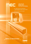
Instructions to follow to fit MEC 800 to a double swinging gate. It is recommended to respect all the steps described in this manual
to achieve a perfectly working installation of the system.
TIE RODS
COVER/END PLUG
HEXAGONAL NUT
PLUG
Installation: remove the anodized aluminium cover by unscrewing the two hexagonal nuts in the front cover plug (see pic. 4). Pull the
cover horizontally and lay bare the cylinder, piston shaft and ball bearing front fixing. The fitting of the rear fixing plate to the gate post
or brick pier can be either by welding, with the use of a square plate as in the picture, or by embedding. Anchor plates are to be used
to secure the actuator plate into the concrete setting. Fixing geometry, ie. distances between hinge centre line of the gate and back
fixing centre line of the actuator, are provided in pictures 5 and 6, on page 4, and pictures 21 to 23 on page 9. These are for long stroke
braking actuators. Follow which applies.
PIC. 4
A
B
Before installing MEC 800 special it is important to check the structure of the gate and make sure that it is adequate to take the actuator,
there must be no problems at all with the gate frame, which must be strong and robust to be electrically operated. It is recommended
to strengthen and fix all the parts that look weak, or worn out, eliminate any friction of the gate against the gate post or pavement (check
the hinges, the gate must be very smooth).
The actuator is mounted to the gate by specially designed plates, one to the gate and one to the gate post (Pic. 5). MEC 800 is very
strong and powerful. The thrust power that it can develop is high and safe. The motor pump unit is fitted with adjustable pressure valves.
It is entirely made of steel and pressure cast aluminium, the temperature range it can safely bear is -20°C +80°C (Pic. 7).
130
Make sure that the distances A and B are A = 140 mm and B = 130 mm respectively measured from the gate hinge centre line to back
fixing centre line. This ensures smooth and even movements of the gate. Distance D is 80 mm from the centre line of the hole in the
front fixing ball to the centre line of the gate plate (pic. 6). (Distances to be referred to only with MEC 800 actuators, 280 mm stroke).
It is important that
the gate hinges are
close to the inside
edge of the gate
post.
Before the square reinforcement plate is finally fixed to the gate, make some tests, the ball bearing head fully screwed in, allowing the
piston to reach the very limit of the permitted stroke. Operate the gate manually to open and close. Try a second time with aluminium
protection cover fitted. Once satisfied that the fixing distances are all right, remove the cover and weld the plate fully as shown in
pictures 5 and 8.
BALL BEARING HEAD
FULLY SCREWED IN
GATE STOP FIXED TO
THE GROUND OPEN
GATE
PROTECT THE SHAFT
WHILE WELDING
140
FIXING PLATE
B
A
80
GATE STOP FIXED TO
THE GROUND CLOSED
GATE
D
PIC. 5 - INSIDE VIEW
Fix the front fixing plates and swing the actuator on to it, the piston shaft must be all out and the thread of ball bearing head all in, ie. not
visible on the outside. The gate fully closed against its ground stop. A spirit level will tell if the actuator is perfectly straight (Pic. 5 - 8).
760
A
280
GATE STOP IN
CLOSED GATE
POSITION
BALL BEARING
FRONT FIXING
B
After completing the fixing operations of the plates, unscrew the ball bearing head 5 or 6 mm approximately and tighten the nut to lock
it in the correct position. This ensures the correct position of the gate on the closed gate stop (Pic. 9)
THREADED NUT
TO ADJUST
FRONT FIXING
PISTON
SHAFT
80
130
140
PIC. 8
D
THE SUM OF A+B MUST TOTAL
PISTON STROKE
FIXING
PLATE
95°
GATE STOP IN
OPEN GATE
POSITION
SPECIAL - 280 mm
REAR BLOCK C/W BRACKET
ALLOWING ROTATION OF THE GATE
DRWG. No. 2432
PIC. 6
PIC. 7
4
5 or 6 mm
PIC. 9
5