1
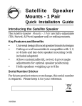
Satellite
Speaker
Mounts - 1 Pair
Quick Installation Guide
Introduction
The Satellite Speaker Mounts - 1 Pair are fully-adjustable (Tilt,
Swivel, & Pivot) speaker wall or ceiling mounts.
Key Features and Benefits
•
•
•
•
Universal design fits most speaker brands & designs
Ceiling or wall mountable & compatible with 1, 2, or
4-hole and key-hole speaker mounting (with included
adapters)
Allows customizable tilt, swivel, & pivot angle
adjustments for optimal speaker positioning
Holds speakers weighing up to 8 lbs
Serial Number Sticker
For future product return or exchange, this serial number is
required. Please keep it for your reference.
04-0600B
1
Package Contents
•
•
•
•
•
•
(2) Speaker mounts
(2) 1-hole adapters
(2) 2/4-hole adapters
(2) 2 ¼” ceiling mount extensions
Mounting hardware
Quick installation guide
Mounting Hardware
M6x20mm Machine Screw
M5 x 20mm Machine Screw
8-32 x 5/8" Machine Screw
1/4"-20 x 1/2" Machine Screw
M5 x 1/8" Plastic Screw
8-32 Hex Key Hole Nut
#8 x 3/4" Self Tapping Screw
#12 x 3/4" Self Tapping Screw
#12 x 1 3/4" Self Tapping Screw
#12-14 Alligator Anchor
M4 x 8mm Flat Head Machine Screw
2
Installation
Please read the instructions prior to installation. This speaker
mount is designed solely for the mounting of small speakers
weighing less than 8lbs. We are not responsible for damage
that may occur if speakers weighing more than 8lbs. are
used.
The user will have to determine which type of configuration
will work best with the included mounting hardware. If the
included hardware does not fit with the application, the
appropriate hardware will have to be purchased.
Single Hole Mounting
1.
Most satellite speakers will require the use of the
M5 x 20mm machine screw used in combination with
M5 x 1/8" plastic washer. The plastic washer is used as
a spacer between the threaded insert and the post, see
Figure 1 below. It is critical the plastic washer is used
correctly.
M5 x 20mm
Machine Screw
Back Speaker
Mounting Post
M5 x 1/8"
Plastic Washer
Figure 1
3
2.
3.
Once the proper configuration is determined, secure
the post to the speaker.
Some speakers use the smaller M4 x 8 screw, which is
inserted into the off-center on the mounting post, see
Figure 2 below.
M4 x 8mm Flat Head
Machine Screw
Back Speaker
Figure 2
4.
Check the size of the hole, make sure you have the
8-32 x 5/8" machine screw, the 1/4"-20 x 1/2" machine
screw, the M6 x 20mm, or the M5 x 20mm fits inside,
see Figure 3 below.
M5 x 1/8" Plastic Washer
Back Speaker
8-32 x 5/8" Machine Screw
1/4"-20 x 1/2" Machine Screw
Figure 3
4
5.
When the correct size is determined, place the screw
through the speaker post and attach to the rear of the
speaker enclosure. If the screw does not tighten
properly, use the M5 x 1/8" plastic washer to tighten
it up.
Key Hole Mounting
1.
2.
If your speaker has a factory key hole design, you will
use the 8-32 x 5/8" machine screws in combination
with the 8-32 Hex Key Hole Nut.
Loosely pre-assemble the mounting post with the
8-32 x 5/8" machine screw and hex key hole nut, see
Figure 4 below.
Keyhole
Mounting Post
M5 x 1/8"
Plastic Washer
8-32 x 5/8"
Back Speaker
Machine Screw
8-32 Hex Key Hole Nut
Figure 4
5
3.
4.
5.
6.
Engage the hex key hole nut into the key hole slot.
Put tension on the assembly by gently pulling back on
the speaker mount post while tightening the
8-32 x 5/8" machine screw, see Figure 4 on page 5.
The hex key hole nut will engage on the housing in the
key hole slot.
If the post does not tighten securely against the
housing, it will be necessarry to use the M5 x 1/8"
plastic washer as a spacer under the head of the
8-32 x 5/8" machine screw, see Figure 4 on page 5.
2/4 Hole Mounting
1.
2.
6
Find the best mounting configuration that matches
your speaker enclosure. Four-hole mount patterns
can be accomodated by positioning the speaker plate
diagonally, see Figure 5 on the next page.
Using the 1/4"-20 x 1/2" machine screws, install the
speaker plate and secure the speaker enclosure, see
Figure 5 on the next page.
Back
Speaker
1/4"-20 x 1/2"
Machine Screw
4-Hole
Orientation
2-Hole Orientation
Figure 5
Self-Tapped Mounting
1.
2.
Locate the optimum location for the mounting plate
and use it as template to mark the drilling locations.
Do not drill or screw into the speaker where you could
possibly damage the internal components.
Drill the pilot hole(s) using a 1/8" drill bit. The holes(s)
should not be drilled more than 1/2" depth, see Figure
6 on the next page.
7
#12 x 3/4" Self
Back Speaker
Tapping Screw
Figure 6
Mounting to the Wall or Ceiling
The mounting hardware for the three different surface
applications is supplied. You will need to determine what
style hardware will work best with your mounting surface.
Always use caution when drilling into a wall or ceiling. Make
sure to avoid all electrical and water lines.
Wood Surface
1.
2.
8
Using a stud finder, locate the wood stud or framing
member. Always mount the speakers in the center of
a stud.
Using the wall plate as a template, mark hole positions
on mounting surface. For in-wall applications, position
the mounting holes in a vertical pattern, see Figure 7
on the next page.
#12 x 1 3/4" Self
Tapping Screw
Figure 7
3.
4.
Drill holes through the drywall and into the wood
stud using a 1/8" drill bit. These holes should be drilled
1 1/2" deep, see Figure 7 above.
After the holes are drilled, mount the wall plate using
the self tapping screws.
Drywall Surfaces
1.
2.
3.
Locate the best mounting location in the ceiling or
wall. Using the wall plate as a template, mark the hole
positions on the mounting surface. For in-wall
applications, position the mounting holes in a vertical
pattern, see Figure 8 on the next page.
Drill holes in the drywall using a 5/16" drill bit.
Once the holes are drilled, insert the alligator anchor
into the holes. Make sure the anchor is flush with the
wall and/or ceiling surface, see Figure 8 on the next
page.
9
4.
With the anchors in place, mount the wall plates using
the #12 x 3/4" self tapping screws, see Figure 8 below.
#12 x 3/4" Self
Pre Drill 5/16"
Tapping Screw
Holes
Insert screw through wall plate
Insert Alligator
and into the alligator anchor
Anchor
Figure 8
Concrete Surface
1.
2.
10
Using the wall plate as a template, mark hole positions
on the mounting surface. For in-wall applications,
position the mounting holes in a vertical pattern, see
Figure 9 on the next page.
Drill holes in the solid concrete or hollow block using
a 5/16" masonry bit. Once the holes are drilled, insert
the # 12-14 alligator anchors into the holes and make
sure the anchor is flush with the surface of the wall, see
Figure 9 on the next page.
Insert Alligator
Anchor
#12 x 3/4" Self
Tapping Screw
Insert screw through wall plate
and into the alligator anchor
Using the hammer to
tap anchor into place
Figure 9
3.
With the wall anchor in place, mount the wall plate
using the #12 x 3/4" self tapping screws, see Figure 9
above.
Extension Mounting
This is for ceiling and/or shelf applications. Do not use
extension in the wall application.
1.
2.
Install a 2 1/4" ceiling mount extension to the wall
plate.
Secure the setscrew to hold the extension in place with
the weight of the speaker attached.
Tighten the allen screw using
the provided allen wrench
Figure 10
11
Low-Profile Mounting
This is for wall and ceiling application.
1.
2.
Install the low-profile portion of the speaker mount to
the wall plate or 2 1/4" extension.
Secure the setscrew to hold the extension in place with
the weight of the speaker attached.
Tighten the allen screw using
the provided allen wrench.
Figure 11
Speaker Mounting
1.
2.
Install the speaker with the speaker post or 2-hole
plate attached.
Secure the screw to hold the extension in place with the
weight of the speaker attached.
Post Style Speaker
Figure 12
12
2-Hole Speaker
Blank Page
13
Blank Page
14
Technical Support and Warranty
QUESTIONS? SIIG’s Online Support has answers! Simply visit our web site at
www.siig.com and click Support. Our online support database is updated daily with
new drivers and solutions. Answers to your questions could be just a few clicks away.
You can also submit questions online and a technical support analyst will promptly
respond.
SIIG offers a 5-year manufacturer warranty with this product. This warranty covers the
original purchaser and guarantees the product to be free of any defects in materials or
workmanship for five (5) years from the date of purchase of the product.
SIIG will, at our discretion, repair or replace (with an identical product or product
having similar features and functionality) the product if defective in materials or
workmanship. This warranty gives you specific legal rights, and you may also have other
rights which vary from state to state. Please see our web site for more warranty details.
If you encounter any problems with this product, please follow the procedures below.
A) If it is within the store's return policy period, please return the product to the store
where you purchased from.
B) If your purchase has passed the store's return policy period, please follow the steps
below to have the product repaired or replaced.
Step 1: Submit your RMA request.
Go to www.siig.com, click Support, then REQUEST A PRODUCT REPLACEMENT
to submit a request to SIIG RMA or fax a request to 510-657-5962. Your RMA request
will be processed, if the product is determined to be defective, an RMA number will
be issued.
Step 2: After obtaining an RMA number, ship the product.
•
Properly pack the product for shipping. All accessories that came with the
original package must be included.
•
Clearly write your RMA number on the top of the returned package. SIIG will
refuse to accept any shipping package, and will not be responsible for a product
returned without an RMA number posted on the outside of the shipping
carton.
•
You are responsible for the cost of shipping to SIIG. Ship the product to the
following address:
SIIG, Inc.
6078 Stewart Avenue
Fremont, CA 94538-3152, USA
RMA #:
•
SIIG will ship the repaired or replaced product via Ground in the U.S. and
International Economy outside of the U.S. at no cost to the customer.
15
About SIIG, Inc.
Founded in 1985, SIIG, Inc. is a leading manufacturer of IT connectivity solutions
(including Serial ATA and Ultra ATA Controllers, FireWire, USB, and legacy
I/O adapters) that bridge the connection between Desktop/Notebook systems
and external peripherals. SIIG continues to grow by adding A/V and Digital
Signage connectivity solutions to our extensive portfolio.
SIIG products offer comprehensive user manuals, many user-friendly features,
and are backed by an extensive manufacturer warranty. High quality control
standards are evident by the overall ease of installation and compatibility of
our products, as well as one of the lowest defective return rates in the industry.
SIIG products can be found in computer retail stores, mail order catalogs,
through major distributors, system integrators, and VARs in the Americas and
the UK, and through e-commerce sites.
PRODUCT NAME
Satellite Speaker Mounts - 1 Pair
FCC RULES: TESTED TO COMPLY WITH FCC PART 15, CLASS B
OPERATING ENVIRONMENT: FOR HOME OR OFFICE USE
FCC COMPLIANCE STATEMENT:
This device complies with part 15 of the FCC Rules. Operation is subject
to the following two conditions: (1) This device may not cause harmful
interference, and (2) this device must accept any interference received,
including interference that may cause undesired operation.
THE PARTY RESPONSIBLE FOR PRODUCT COMPLIANCE
SIIG, Inc.
6078 Stewart Avenue
Fremont, CA 94538-3152, USA
Phone: 510-657-8688
Satellite Speaker Mounts - 1 Pair is a trademark of SIIG, Inc. SIIG and the SIIG logo are
registered trademarks of SIIG, Inc. All other names used in this publication are for identification
only and may be trademarks of their respective owners.
November, 2011
Copyright © 2011 by SIIG, Inc. All rights reserved.