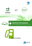
1
INSTALLATION MANUAL MODEL: CCL-WBC-TOUCH-32 WALLBOX TOUCH SERIES Wallbox Touch Series – Installation manual This document is copyrighted, 2015 by Circontrol, S.A. All rights are reserved. Circontrol, S.A. reserves the right to make improvements to the products described in this manual at any time without notice. No part of this manual may be reproduced, copied, translated or transmitted in any form or by any means without the prior written permission of the original manufacturer. Information provided in this manual is intended to be accurate and reliable. However, the original manufacturer assumes no responsibility for its use, or for any infringements upon the rights of third parties that may result from its use. All other product names or trademarks are properties of their respective owners. V1.1, June edition 2015 CCL-WBC-TOUCH-32 INSTALLATION MANUAL CONTENTS 1 PREFACE ............................................................................................................................. 4 2 INSTALLATION GUIDELINES ............................................................................................. 5 2.1 IMPORTANT SAFETY INSTRUCTIONS....................................................................... 5 2.2 ELECTRICAL WIRING CONSIDERATIONS ................................................................. 6 2.3 SPACE REQUIREMENTS ............................................................................................ 7 3 PRODUCT DIMENSIONS ..................................................................................................... 8 4 PRODUCT OVERVIEW ........................................................................................................ 9 5 COMPONENT PARTS LOCATION .................................................................................... 10 6 INSTALLATION .................................................................................................................. 11 6.1 SUPPLIED MATERIAL ................................................................................................ 11 6.2 OPENING THE UNIT ................................................................................................... 12 6.3 CABLE INSERTION .................................................................................................... 13 6.3.1 CABLE INSERTION FROM ABOVE / BELOW ................................................... 14 6.3.2 CABLE INSERTION FROM BEHIND .................................................................. 15 6.3.3 RECOMENDATIONS .......................................................................................... 16 6.4 6.4.1 MATERIAL NEEDED........................................................................................... 17 6.4.2 CONSIDERATIONS ............................................................................................ 17 6.4.3 INSTALLATION ................................................................................................... 18 6.5 7 FIXATION PROCEDURE ............................................................................................ 17 ELECTRICAL INSTALLATION .................................................................................... 20 6.5.1 PROTECTIONS ................................................................................................... 20 6.5.2 WIRING ............................................................................................................... 21 6.6 SIM CARD (FOR 3G MODELS) ................................................................................... 22 6.7 ETHERNET CONNECTION ........................................................................................ 24 6.8 CLOSING THE UNIT ................................................................................................... 25 CABLE HOLDER INSTALLATION .................................................................................... 26 7.1.1 MATERIAL NEEDED........................................................................................... 26 7.1.2 INSTALLATION ................................................................................................... 27 8 UNIT VERIFICATION .......................................................................................................... 29 9 ADDITIONAL SETTINGS ................................................................................................... 30 9.1 PROGRAMMING MASTER TAG ................................................................................ 30 9.1.1 ADD/DELETE A NEW MASTER TAG ................................................................. 30 9.1.2 RESET MASTER TAG ........................................................................................ 32 2 © CIRCONTROL www.circontrol.com CCL-WBC-TOUCH-32 INSTALLATION MANUAL 9.2 DISPLAY LANGUAGE ................................................................................................ 32 9.3 CHANGE MAX. CURRENT OF SOCKET.................................................................... 34 9.4 SET DATE AND TIME ................................................................................................. 35 9.5 MENU TABLE .............................................................................................................. 36 10 TECHNICAL DATA ............................................................................................................. 38 3 © CIRCONTROL www.circontrol.com CCL-WBC-TOUCH-32 INSTALLATION MANUAL 1 PREFACE THE FOLLOWING SYMBOLS ARE USED FOR IMPORTANT SAFETY INFORMATION IN THIS DOCUMENT ELECTRIC RISK! Take precautions to make the electrical connection inside the unit. Unit must be disconnected from any power source during commissioning. ATTENTION! Indicates that the damage to property can occur if appropiate precautions are not taken. This manual provide commissioning information for Wallbox Touch Series, which has been designed and tested to allow electric vehicle charging, specified in IEC 61851. This document has different sections where describes electrical components inside the charge station and a step-by-step installation procedure. Certification Complies with IEC 61851, Electric vehicle conductive charging system (IEC 61851-1) Complies with IEC 62196, Plugs, socket-outlets, vehicle couplers and vehicle inlets Conductive charging system (IEC 62196-1 and IEC 62196-3). RFID complies with ISO 14443A 4 © CIRCONTROL www.circontrol.com CCL-WBC-TOUCH-32 INSTALLATION MANUAL 2 INSTALLATION GUIDELINES 2.1 IMPORTANT SAFETY INSTRUCTIONS Read carefully all the instructions before starting to ensure properly installation of the charge point. The charge point is designed for installation in indoor and outdoor areas. For each of the different conditions of installation, the unit must be installed safely and ensure adequate protection. Charge point must not be installed in areas where there is potential risk of explosions. Do not install the charge point where falling objects may damage the equipment. Wall surface where the charge point is placed must withstand the mechanical forces. Do not use this unit for anything other than electric vehicle charging modes are expected in IEC 61851. Do not modify this unit. If modified, CIRCONTROL will reject all responsibility and the warranty will be void. Comply strictly with electrical safety regulations according to your country. Do not make repairs or manipulations with the unit energised. Only trained and qualified personnel should have access to lowvoltage electrical parts inside the device. Check the installation annually by qualified technician. Remove from service any item that has a fault that could be dangerous for users (broken plugs, caps that don’t close...). Use only Circontrol supplied spare parts. Do not use this product if the enclosure or the EV connector is broken, cracked, open, or shows any other indication of damage. Refer to TECHNICAL DATA section for more information about environment installation conditions. 5 © CIRCONTROL www.circontrol.com CCL-WBC-TOUCH-32 INSTALLATION MANUAL 2.2 ELECTRICAL WIRING CONSIDERATIONS Before start with the wiring connection of the charge point shall take in consideration this section. 1. Charge point – Input power supply Charge point does not include elements of electrical protection. The input power supply line must be hardwired from a distribution board to the charge point under electrical safety regulations according to your country regulations. Minimum safety required protections: - RCD: Type A. IΔN=0.03A. - MCB: maximum value according to the maximum output current of the charge point. Refer to TECHNICAL DATA section for further information. 2. Power supply Line dimensioning The dimensioning of the input power supply line of the charge point must be checked by a qualified electrician. Note that various factors such as cable length between distribution board and charge point, maximum output current of the charge point may have influence of the selected cable. In such cases, increasing the cable cross-section it is required to adapt the temperature resistance of the power supply line. 3. Charge point – Maximum current output If the power supply is less than maximum output current of the charge point, and adjustment to a lower nominal current must be performed using the integrated keypad of the charge point. Please refer to ADDITIONAL SETTINGS section in order to know how to change this value. Please refer to the TECHNICAL DATA section to consult the default factory settings from maximum output current of the charge point. Depending of the model this value may vary. 6 © CIRCONTROL www.circontrol.com CCL-WBC-TOUCH-32 INSTALLATION MANUAL 2.3 SPACE REQUIREMENTS When installing the equipment respect minimum distances space for maintenance and safety reasons. Cable holder (supplied) must be installed under the charge point. Take into account the required space during the installation. Minimum height y recommended is: 1,2m. Please comply accordingly to your country specifications. Units specified in mm 7 © CIRCONTROL www.circontrol.com CCL-WBC-TOUCH-32 INSTALLATION MANUAL 3 PRODUCT DIMENSIONS Units specified in mm 8 © CIRCONTROL www.circontrol.com CCL-WBC-TOUCH-32 INSTALLATION MANUAL 4 PRODUCT OVERVIEW 1 2 3 4 5 6 7 1. Liquid Cristal Display 4. RFID Reader 7. Type 1 tethered cable 2. Keypad 5. Front cover 3. Plug status beacon 6. Cable holder . 9 © CIRCONTROL www.circontrol.com CCL-WBC-TOUCH-32 INSTALLATION MANUAL 5 COMPONENT PARTS LOCATION 2 3 4 5 1 6 7 1. Plug – LED beacon 4. Plug – Meter 7. Plug – Contactor 2. CCL1-Mini Device 5. 12VDC Power Supply 8. AC Terminals 10 8 3. Cellular modem 6. Plug – Mode 3 © CIRCONTROL www.circontrol.com CCL-WBC-TOUCH-32 INSTALLATION MANUAL 6 INSTALLATION 6.1 SUPPLIED MATERIAL MATERIAL Qty Charge point 1 Cable holder 1 Installation manual 1 Cable gland M25x1.5 1 CirCarLife RFID Mifare card 1 11 © CIRCONTROL www.circontrol.com CCL-WBC-TOUCH-32 INSTALLATION MANUAL 6.2 OPENING THE UNIT STEP ACTION Remove 6 screws from the front cover in order to open the unit: 1. Beware of the cables between cover and base when wall mounted unit is opened during the installation tasks. 12 © CIRCONTROL www.circontrol.com CCL-WBC-TOUCH-32 INSTALLATION MANUAL 6.3 CABLE INSERTION There are three possibilities to insert the electric wires or electric pipe: a) Cable insertion from above. b) Cable insertion from behind. c) Cable insertion from below. In all cases it is required to install a cable gland to ensure properly installation. Cable insertion from above Cable insertion from behind Cable insertion from below Protect the contactor and all possible electronic devices inside the unit before breaking the cable insertions. 13 © CIRCONTROL www.circontrol.com CCL-WBC-TOUCH-32 6.3.1 INSTALLATION MANUAL CABLE INSERTION FROM ABOVE / BELOW There are three insertion openings available at the top and bottom sides of the charge point. - Before break out the required openings, take into account the space between internal electronic and wires inside the charge point. - Use a hammer and a flathead screwdriver and carefully break out the cable insertion openings. TOP / BOTTOM VIEW Do not make new holes in others parts of the enclosure. Use only the cable insertion openings to install the required electric pipes. Install always cable glands to ensure IP protection of the charge point. 14 © CIRCONTROL www.circontrol.com CCL-WBC-TOUCH-32 6.3.2 INSTALLATION MANUAL CABLE INSERTION FROM BEHIND There are two insertion openings available at the rear of the charge point. - Before break out the required openings, take into account the space between internal electronic and wires inside the charge point. - Use a hammer and a flathead screwdriver and carefully break out the cable insertion openings. FRONT VIEW Do not make new holes in others parts of the enclosure. Use only the cable insertion openings to install the required electric pipes. Install always cable glands or a double membrane seals to ensure IP protection of the charge point. 15 © CIRCONTROL www.circontrol.com CCL-WBC-TOUCH-32 6.3.3 INSTALLATION MANUAL RECOMENDATIONS Ethernet communications wiring is optional; the unit can operate as standalone. Please provide communications to the unit if it is required to remote monitoring or use OCPP integration. Use only one of the following interfaces: - Ethernet communications (all models). - Integrated 3G modem (only 3G models). Please take attention into the following instructions: * * Ethernet communications cable (if Optional necessary) should be introduced at the top of the unit and power supply wires below the unit. Power wires and communications wires must be installed using different electrical pipes to ensure properly function of the charge point. 16 © CIRCONTROL www.circontrol.com CCL-WBC-TOUCH-32 INSTALLATION MANUAL 6.4 FIXATION PROCEDURE 6.4.1 MATERIAL NEEDED Below list material (Not included) is needed to attach the unit to the wall: MATERIAL Qty PICTURE DIMENSIONS Wall plug 4 Ø6 Screws 4 4x45mm All images shown in the above table are approximate and may vary depending on the surface where the charge point is installed. 6.4.2 CONSIDERATIONS Water drainage from the top side to the rear side of the unit must be ensured. Charge point must be installed vertically. Use a flat surface. Use a level tool to ensure installation at an angle of 90º. 17 © CIRCONTROL www.circontrol.com CCL-WBC-TOUCH-32 6.4.3 INSTALLATION MANUAL INSTALLATION STEP ACTION Adjust the position of the charge point according to the correct vision and management for the end user. 2. Minimum recommended height: 120cm Please comply to your country specifications. 1. Mark 4 holes taking into account the above measurements. 2. Place it on a flat surface. 3. 3. Use 4x45mm screws to attach the unit to the wall. 4. Check charge point has REAR VIEW no inclination using a level tool. Units specified in mm 18 © CIRCONTROL www.circontrol.com CCL-WBC-TOUCH-32 INSTALLATION MANUAL 4. a b b a) Use Ø 6 drill size to make the 4 holes into the wall. b) Install the anchor according to the surface material. 5. Recommended screw dimensions: 4x45mm Use only the holes indicated in the picture above to insert and anchor the unit to the wall. Do not make new holes in other parts of the plastic from the unit; otherwise water can enter into the unit when it rains. All screws and wall plugs needed to attach the unit to the wall are not included. . 19 © CIRCONTROL www.circontrol.com CCL-WBC-TOUCH-32 INSTALLATION MANUAL 6.5 ELECTRICAL INSTALLATION 6.5.1 PROTECTIONS Charge point does not include elements of electrical protection. Please provide a Miniature Circuit Breaker (MCB) and a Residual Circuit Breaker (RCD) externally to protect the unit electrically. Charge point is set to 32A from factory default settings. Power supply wires should be introduced below of the unit. Please refer to ELECTRICAL WIRING CONSIDERATIONS before proceeding to the wiring installation. 20 © CIRCONTROL www.circontrol.com CCL-WBC-TOUCH-32 6.5.2 INSTALLATION MANUAL WIRING SINGLE-PHASE WIRING - Perform the 230V AC Single-phase connection as shown. - Do not forget to connect the ground cable (PE) to the supply terminal. L N 21 PE © CIRCONTROL www.circontrol.com CCL-WBC-TOUCH-32 INSTALLATION MANUAL 6.6 SIM CARD (FOR 3G MODELS) Please, follow bellow procedure to insert SIM card in CCL1Mini embedded modem. STEP ACTION Locate Control module CCL1Mini. Cellular modem is installed in the same CCL1Mini board as shown: 6. SIM card holder is located at the left side cellular modem. See image below: 7. 22 © CIRCONTROL www.circontrol.com CCL-WBC-TOUCH-32 INSTALLATION MANUAL The SIM card and its contacts can be easily damaged by scratches or bending, so be careful when handling, inserting or removing the card. Insert the SIM card with the contact surface facing down. 8. The image below shows how it should be done. 23 © CIRCONTROL www.circontrol.com CCL-WBC-TOUCH-32 INSTALLATION MANUAL 6.7 ETHERNET CONNECTION Charge station can be configured and monitorized to establish owner preferences or specific setup using integrated Ethernet communication port installed at the bottom of the CCL1Mini module. CCL1-Mini Module This unit is shipped from the factory with default network setting of “DHCP enabled”. It means that the charge station will try to obtain an IP address automatically from the network (if it is available). 24 © CIRCONTROL www.circontrol.com CCL-WBC-TOUCH-32 INSTALLATION MANUAL 6.8 CLOSING THE UNIT STEP ACTION Place back 6 screws from the front cover in order to close the unit: 9. Beware of the cables between cover and base while closing the unit. 25 © CIRCONTROL www.circontrol.com CCL-WBC-TOUCH-32 INSTALLATION MANUAL 7 CABLE HOLDER INSTALLATION 7.1.1 MATERIAL NEEDED Below list material (Not included) is needed to attach the unit to the wall: MATERIAL Qty PICTURE DIMENSIONS Wall plug 3 Ø6 Screws 3 4x45mm All images shown in the above table are approximate and may vary depending on the surface where the cable holder is installed. 26 © CIRCONTROL www.circontrol.com CCL-WBC-TOUCH-32 7.1.2 INSTALLATION MANUAL INSTALLATION STEP ACTION Adjust the position of the cable holder under the charge point as shown below: 10. 1. Mark 3 holes taking into account the above measurements. 2. Place it on a flat surface under the charge point. 11. 3. Use 4x45mm screws to attach the holder to the wall. 4. Check the holder has no inclination using a level tool. REAR VIEW Units specified in mm 27 © CIRCONTROL www.circontrol.com CCL-WBC-TOUCH-32 INSTALLATION MANUAL 12. a b b a) Use Ø 6 drill size to make the 3 holes into the wall. b) Install the anchor according to the surface material. 13. Recommended screw dimmensions: 4x45mm All screws and wall plugs needed to attach the holder to the wall are not included. . 28 © CIRCONTROL www.circontrol.com CCL-WBC-TOUCH-32 INSTALLATION MANUAL 8 UNIT VERIFICATION Once all installation procedure has been performed, check points below: 1. Be careful when closing the cover all wires remain within the unit. 2. Check each plug is in proper conditions before start operation. 3. Check no abnormal noise appears while unit is charging. 4. Check all beacons indicators are lighting. Below table shows possible LED beacon colors: PLUG STATE BEACON COLOR Available Green Charging Blue Fault Red 29 © CIRCONTROL www.circontrol.com CCL-WBC-TOUCH-32 INSTALLATION MANUAL 9 ADDITIONAL SETTINGS WallBox Touch series are equipped with a keypad to access to the settings menu in order to configure easily the charge point. Firmware version * CCL1-M 2.0 *Firmware version is displayed during power up of the unit. 9.1 PROGRAMMING MASTER TAG There is no restriction to access to the settings menu by default factory settings. Master Tag is an optionally function to restrict the access to the settings menu in order to avoid configuration changes. 9.1.1 ADD/DELETE A NEW MASTER TAG Only one RFID card can be added as a Master Tag. 1. Press 2. Use button to access to the menu. or 3. Press 4. Use 5. Press until finding Setup option. button. or buttons until finding Master tag option. button. 6. Only one of the following options is shown: 30 © CIRCONTROL www.circontrol.com CCL-WBC-TOUCH-32 INSTALLATION MANUAL 6.a. Add a new Master Tag: set one RFID card as a Master Tag. 6.a.1. Wait until “Show card to the reader” is shown by display. 6.a.2. Show the new Master Tag to the reader 6.a.3. Press 6.a.4. If the procedure has been successfully applied display shows button to apply changes. “Master tag saved”. 6.a.5. The Master Tag is now programmed. Keep this card in a safe place. 6.b. Delete Master Tag: delete the current Master Tag configured. 6.b.1. Press button to delete the Master Tag. 6.b.2. If the procedure has been successfully applied display shows “Master tag deleted”. 6.b.3. No Master Tag is now programmed. There are no restrictions to enter into the settings menu. 7. Press 3 times NOTE button to save settings and exit. Charge point only asks for the Master tag every time the button is pressed to enter to the settings menu (only if Master Tag has been configured previously). 31 © CIRCONTROL www.circontrol.com CCL-WBC-TOUCH-32 9.1.2 INSTALLATION MANUAL RESET MASTER TAG Follow the procedure below if the Master Tag is lost or stolen: 1. Power OFF the charge point. 2. Power ON back again. 3. Wait until the LED lights back again. 4. Press simultaneously until display shows: “Press OK to reset and Master Tag”. If the message does not appears, please go back to step number 1 and try again. 5. Press to delete the Master Tag. button If “Master Tag deleted” is shown by display. a. Press 6. Now the Master Tag is deleted from the charge point. You can program a new Master Tag or allow free access to the settings menu. 9.2 DISPLAY LANGUAGE The display messages of the charge point are available in different languages. Follow procedure below to change the language according to the preferred language: 1. Press button to access to the menu. 2. If one Master Tag has added before, display shows “Show Master Tag to the reader”. Show Master Tag to access to the settings menu. 3. Use 4. Press 5. Use 6. Press or buttons until finding Setup option. button. or buttons until finding Language option. button. 32 © CIRCONTROL www.circontrol.com CCL-WBC-TOUCH-32 7. Use 8. Press INSTALLATION MANUAL or buttons until finding desired language. button to accept or 9. Press 3 times button to cancel. button to exit and save settings. 10. Wait 1 minute approximately until the charge point has completely rebooted. 33 © CIRCONTROL www.circontrol.com CCL-WBC-TOUCH-32 INSTALLATION MANUAL 9.3 CHANGE MAX. CURRENT OF SOCKET If the power supply is less than the maximum output current of the charge point, use the following procedure to set a lower current rating: 1. Press button to access to the menu. 2. If one Master Tag has added before, display shows “Show Master Tag to the reader”. Show Master Tag to access to the settings menu. 3. Use 4. Press 5. Use or button. or 6. Press 7. Use 8. Press 9. Use 10. Press buttons until finding Setup option. buttons until finding Max. Intensity of socket option. button twice. or buttons to change the tens. button. or to change the units. button. 11. Press 3 times button to exit and save settings. 34 © CIRCONTROL www.circontrol.com CCL-WBC-TOUCH-32 INSTALLATION MANUAL 9.4 SET DATE AND TIME Date and time is set from factory as UTC format (Universal Time Coordinated). It is highly recommended to set the correct date and time according to your time zone. 1. Press button to access to the menu. 2. If one Master Tag has added before, display shows “Show Master Tag to the reader”. Show Master Tag to access to the settings menu. 3. Use or 4. Press 5. Use button. or 6. Press 7. Use until finding Setup option. buttons until finding Date/Time option. button. or to change the current value that is flashing on the display and button to change the next value. To cancel procedure press 8. When the last value is changed, press 9. Press 3 times button. button to accept. button to exit and save settings. 35 © CIRCONTROL www.circontrol.com CCL-WBC-TOUCH-32 INSTALLATION MANUAL 9.5 MENU TABLE The menu table will help you to understand the menu selections and options available in the Touch series charge points. Factory settings are shown in Bold. Press button to access to the menu. Before making changes, check that no vehicles are charging otherwise the current charge session stops. Level 1 Level 2 Options Description There is no Master Tag configured Master Tag Add New Master Tag from factory. Delete Master Tag Set a Master Tag to restrict access to the menu. Depending on the model, the maximum intensity of the plug may vary. Max. Intensity of the socket Please refer to technical data for 6 – 32 A more information. Optionally you increase/decrease Setup can the change maximum intensity of the socket using the up and down buttons. Catalan English Finnish Language French LCD display language. German Change Italian according to the preferred language. the display messages Norwegian Spanish Swedish Date/Time - Date and time of the charge point. 36 © CIRCONTROL www.circontrol.com CCL-WBC-TOUCH-32 Level 1 INSTALLATION MANUAL Level 2 Options Description Energy Meter - Total active energy of meter (kWh). Total Time - Total usage time (minutes). Enabled Maximum time limitation. Disabled Disabled from default factory settings. Totals Status Time limit You can set from 1 to 99 minutes. Time limitation 1 to 99 Minutes Configurable using up and down buttons. Status Credits Enabled Circontrol prepayment Disabled embedded in RFID cards. 1 to 99 Credits Prepayment only solution works with CirCarLife Cards. Prepayment You can establish your own tariff Tariff 0.01 to 99.99 Credits using the menu. Default: 4 Credits Default: 0,15 credits/kWh Local white-list. Registered Users - Add/Remove/List all the allowed cards configured in the local white list. User Management Remove User - By default all cards are allowed to start charging. When one or more cards are added to the list, others Add User cards are not allowed to use the - charge point (only listed cards). Status Start Time Enabled Timer to delay start charging. Disabled Charge - stopped by the same card that was transaction can only be used to start charging. Timer Important: you must show before a End Time Option disabled RFID card to start the session and the charge transaction will start at the start time. 37 © CIRCONTROL www.circontrol.com CCL-WBC-TOUCH-32 INSTALLATION MANUAL 10 TECHNICAL DATA CCL-WBC-TOUCH-32 AC INPUT AC Power supply 1P + N + PE AC Voltage 230VAC +/- 5% Nominal input current 32A Nominal input power 7,4kW Frequency 50 / 60 Hz OUTPUT PLUG Charge system Mode 3 Sockets/ Plugs Type 1 tethered cable Lock system No Maximum output power 7,4kW Maximum output current 32A Output voltage range 230VAC (1P + N + PE) ENERGY METERS Class 1 – EN62053-21 Accuracy class in active energy Meter standards EN62052-11, EN62053-21, EN62053-23, EN61010-1 NETWORK Ethernet 10/100BaseTX GENERAL Enclosure rating IP54 / IK10 Enclosure material ABS Operating temperature -10 to +45ºC Operating humidity To 95% RH Non-condensing RFID system ISO / IEC14443A / B Display LCD Backlight double line text Power limit control Mode 3 PWM control according ISO / IEC 61851-1 Interface protocol OCPP / XML Net weight 3Kg OPTIONAL DEVICES Mobile communications 3G / GPRS Extended operating temperature (Optional Heater) -30…+45ºC 38 © CIRCONTROL www.circontrol.com www.circontrol.com