1
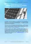
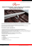
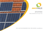
GRACE SOLAR ROOF MOUNTING SYSTEM INSTALLATION Manual XIAMEN FENGWEI ENERGY TECHNOLOGY CO., LTD. Solar Roof Mounting System Installation Manual Contents Chapter Title Page 1 General information 3 2 Safety and Installer Responsibilities 4 3 Technical Specifications 5 4 Tools for Installation 6 5 Components Description 7 6 System overview 9 7 Designing the module field 10 8 Code-compliant AS/NZS 1170 planning 11 9 Installation 14 10 Warranty 19 Version 1.0 2 / 19 Solar Roof Mounting System Installation Manual 1. General information Thank you for choosing the Grace solar roof mounting system. Made from custom-built aluminum extrusions and components, Grace Solar’s innovated design and improved frame strength greatly simplify solar panel installation. The easy installation four steps make the Tilt-in modules can be put into the GR Rail on any position quickly. So, the Tilt-in modules is pre-assembly with the clamp to save your install time. Easy installation four steps Grace solar’s versatile design makes it suitable for a wide variety of building types and zones including residential, commercial and remote environments. Gracesolar is backed by a 10-year warranty and is compliant with the Australian/New Zealand Standard on Wind Actions (AS/NZS1170). Version 1.0 3 / 19 Solar Roof Mounting System Installation Manual 2. Safety and Installer Responsibilities 2.1 Handling and Installing Grace solar ››» It is critically important that safety practices are observed when installing Do not throw or roughly handle any Grace solar components. Do not bring Grace solar system into contact with sharp or heavy objects. Do not modify Grace solar components in any way. The exchange of bolts, drilling of holes, bending or any other physical changes not described in standard installation procedure will void the warranty. Caution It is the installer’s responsibility to verify the integrity of the structure to which Grace solar components is fixed. Roofs or structures with Installation of this rotten/rusted bearers, undersized bearers, excessively spaced bearers, product is to be or any other unsuitable substructure cannot be used with Grace solar performed only by components, and installation on such structures will void the warranty, professionally and could result in death or serious injury. trained installers. Any attempt by an unqualified person to install this product could result in death or serious injury. 2.2 Wind and Climate Design AS/NZS1170.2 provides guidance on determining the wind pressures applicable to your Grace solar system install site, taking into account roof shape and geographic location. Sufficient guidance is given in this document, but you may wish to procure a copy of these standards if your company installs Australia/New Zealand wide. REMEMBER average wind speeds are higher for structures mounted closer to the roof perimeter zone (edge). Refer to ‘Fixing within Roof Installation Zone’ for more information) Make sure your installation complies with local and national building codes. Take into account relevant design parameters (wind speed, exposure and topographic factor) when determining the loading for the installation. If alternative fasteners are used to ix the framing to the roof (assuming supplied fasteners are unsuitable for any reason), all screw fasteners must conform to corrosion resistance Class 4 Australian Standard AS3566 and be of equal or greater strength to those supplied with your Grace solar system order. Version 1.0 4 / 19 Solar Roof Mounting System Installation Manual 3. Technical Specifications 3.1 Applications Commercial and residential buildings Marine applications and remote areas 3.2 Features Caution 6005-T5 Aluminum extrusion Innovated designed of the Tilt-in modules, which can be pre-assembly with the clamp, make the installation easy and quick. Refer to the section “Designing market. Your System” before attempting Suitable for difference conditions and the most solar panels at present Significantly higher strength-to-weight ratio than other framing products, installation. Failure providing improved efficiency due to greater frame spans, inherent to correctly corrosion resistance resulting in low ongoing maintenance and an establish the extended product life. requirement of the AS/NZS1170.2 proposed installation site is Complies with Australian/New Zealand Standard on Wind Actions, Anodized finish dangerous and will void the framing 3.3 Material warranty. Material Tensile strength Ultimate Yield 260MPa 240Mpa Stainless Steel 304 635MPa 235MPa Stainless Steel A2-70 700MPa 450Mpa 6005-T5 Aluminum Extruded 3.4. Installation condition Version 1.0 Roof slope 0°to 60° Building height Up to 20m Mounting structure Timber Roof types Flat or pitched steel and tile System angle Flushed with the roof 5 / 19 Solar Roof Mounting System Installation Manual 4. Tools for Installation The following tools are required for the installation: 6 mm Allen key or hexagonal driver bit. If using a 6mm driver bit, make sure the cordless power tool used for the driving has a hand-tight clutch setting a fine (soft) impact drive to prevent damage to the fragile glass panels and threads on the Structure. Cordless drill; Drill or impact driver for driving roof material fixings Angle grinder; For terracotta tile roof installation, and angle grinder fitted with a continuous edge diamond tipped tile0cutting blade; gloves, hearing protection, a face protection mask, and a suitably rated breathing protection mask for all people in proximity of grinding Gloves; Protect the hazard of the sharp corners. Cord or color pen; Mark the installation position; Spirit level Rule If necessary, timber to shim the roof hooks Version 1.0 6 / 19 Solar Roof Mounting System Installation Manual 5. Components Description GR Rail hold each panel row length can be customized 6005-T5 extruded aluminum Standard Rail Length 808~826mm wide 990~1020mm wide panels panels 2560mm 3405mm 4200mm GR Rail Splice Kit Extend GR Rail to any length as required by the quantity or width of the solar panels Inter Clamp Kit for Framed Modules Fit between two panels Fastened with a 6mm Allen key Standard pre-assembly for the usual panels with thickness 30, 35, 40, 46, 50, 57mm End Clamp Kit for Framed Modules Hold the edge of each end panels Fastened with a 6mm Allen key Standard pre-assembly for the usual panels with thickness 30, 35, 40, 46, 50, 57mm Adjustable End Clamp Kit Hold the edge of each end panels Fastened with a 6mm Allen key Adjustable for the panels with thickness from 25~60mm Version 1.0 7 / 19 Solar Roof Mounting System Installation Manual Variety of Roof Hook Stainless Steel Roof Hook 1 # Fix to the rafter below Roman tile roof Include 3pcs st6.3x80 wood screws Stainless Steel Roof Hook 2 # Fix to the rafter below flat tile roof Include 2pcs st6.3x80 wood screws Stainless Steel Roof Hook 3 # Side fix to the rafter below Roman tile roof Include 3pcs st6.3x80 wood screws Stainless Steel Roof Hook 4# Fix to the rafter on slate tile roof Include 3pcs st6.3x80 wood screws Aluminum Tin Roof Hook 5# Fix to the purlin on tin roof Include 1pcs st6.3x80 wood screws Stainless Steel Roof Hook 6# Fix to the rafter below Roman tile roof Include 3pcs st6.3x80 wood screws Accessories Grounding Clip Installed under two panels Stainless Steel 304 Grounding Lug Aluminum Lay-in lug to connect wires Pre-assembly Copper Grounding Lug Copper Lay-in lug to connect wires Pre-assembly Excellent electric conductivity Version 1.0 8 / 19 Solar Roof Mounting System Installation Manual 6. System overview All components of the system are listed below. The version and quantities of the parts can vary, depending of Type of roof Type of module Number of modules Site specifics ① GS Rail ② GS Rail Splice ③ Inter Clamp ④ End Clamp ⑤ Roof hook Version 1.0 9 / 19 Solar Roof Mounting System Installation Manual 7. Designing the module field Below, the distances between roof connections for a portrait installation are specified. Clamp-on roof hooks need to be installed in specific distances, depending on the distance of rafters and the stoical conditions. 1. Height of the module field: module height x number of modules vertically 2. Width of the module field: number of modules horizontally x (width of the module + 18 mm)+32 mm 3. Distance between roof connections vertically (according to the clamping points pre-defined by the module producer): Quarter-points of the modules, about 1/2 of module height. 4. Distance between roof connections horizontally: Depending on the distance between rafters and on the static requirements (please see the Chapter 8 on page 20). 5. Distance between modules: 17 mm When positioning the modules, please take into consideration That the values above are That dimensions of tiles or other roof covering and the position of the rafters define the precise actual horizontal distance between roof connections That the distance between roof laths defines the precise actual vertical distance between roof connections. Version 1.0 10 / 19 Solar Roof Mounting System Installation Manual 8. code-compliant AS/NZS 1170 planning 8.1 Determine the wind region of your installation site Region Definition: Wind regions are pre defined for all of Australia by Australian Standard 1170. The Wind Region has nothing to do with surrounding topography or buildings. • Most of Australia is designated Region A which indicates a Regional Ultimate Basic Wind Velocity of 45msec. • Some areas are designated Region B (57msec). Local authorities will advise if this applies in your area. • Region C areas (66msec) are generally referred to as Cyclonic and are generally limited to northern coastal areas. Most Region C zones end 100km inland. • Region D (80msec) Australia's worst Cyclonic Region between Carnarvon and Pardoo in Western Australia. 8.2. Determine the height of the of your installation site This document provides sufficient information for Grace solar system installation height less than 20 meters. If your installation site is more than 20 meters in height, please contact Grace solar to obtain Version 1.0 11 / 19 Solar Roof Mounting System Installation Manual engineering data to support your installation. 8.3 Determine the Maximum Rail Support Spacing Please use the following table to determine the GR Rail support spacing for tile roof installations. Installation Height 5 Meters 10 Meters 15 Meters 20 Meters 1650mm Long Panels fixed to Tiled Roof Region A Region B Region C (mm) (mm) (mm) 2130 1690 1380 1940 1540 1260 1840 1460 1190 1740 1380 1130 Region D (mm) 1080 990 940 890 The above figures are based on modules lengths of up to 1650mm, maximum weight of 21Kg 1650mm modules requires 2 rails with fixing as per table above The above spacing applies for fixing through thin sheet purlins (greater than 1.0mm thickness) or a minimum embedment of 50mm into timber purlins. Tile brackets should fixed to the rafter using two mounting screws (M6x80mm) Please use the following table to determine the base rail support spacing for sheet metal roof installations. Installation Height 5 Meters 10 Meters 15 Meters 20 Meters 1650mm Long Panels fixed to Tin Roof Region A&B (mm) Region C&D (mm) 1320 770 1200 700 1140 665 1080 630 The above figures are based on modules lengths of up to 1650mm, maximum weight of 21Kg 1650mm modules requires 2 rails with fixing as per table above The above spacing applies for fixing through thin sheet purlins (greater than 1.0mm thickness) or a minimum embedment of 50mm into timber purlins. The L Feet should be fixed to the purlins under using one Mounting Screw (M6x80mm) through sheet metal roofs with desk rubber. 8.4 Verify acceptable Rail End Overhang Rail End Overhang must equal 50 percent or less of foot spacing. Thus, if foot spacing is 1200mm, the Rail End Over hang can be up to 600mm. In this case, two feet can support a rail of as much as 2400mm (1200mm between the feet and 600mm of overhang at each end). 8.5 Determine Roof slope Grace solar system can be used for roof slope up to 60 degrees. Please verify the Installation site roof slope should be between 0 degrees and 60 degrees. Version 1.0 12 / 19 Solar Roof Mounting System Installation Manual 8.6. Determine Roof Installation Roof Areas Grace solar system should not to be installed within the minimum of 0.2b and 0.2d of a roof edge or ridge where b and d are the plan dimensions of the building. Version 1.0 13 / 19 Solar Roof Mounting System Installation Manual 9. Installation Install on Roman Tile Roof 1. Remove the roof tiles at the marked positions or simply lift them up slightly. 2. Input the roof hook to the wooden beam. Fix the roof hooks with 3x wood screws (M6x80). 3. Cover the hooks by the removed tile 4. The roof hook must not press against the roof tile. Place it flat. If necessary, shim the roof hook with wood. Wrong Correct 5. If necessary, use an angle grinder or hammer to cut a concavity in the tile that covers the roof hook at the point where the roof hook comes through. (Caution! Must not use fixed roof hook as a ladder, as this extreme point load could damage the tile below. Version 1.0 14 / 19 Solar Roof Mounting System Installation Manual Install on Plain Tile Roof 6. Mark roof hook installation points, and cut recesses for hooks into plain tiles/slate at each installation point. 7. Cut titanium zinc metal sheets to fit and install them under the roof hooks. Fix the roof hooks to the rafter using two 6 x 80 mm wood screws. Install on Tin Roof 8. Mark roof hook installation points and use the power tool to drill the wood screw through the point to fasten the L feet with the purlin. Version 1.0 15 / 19 Solar Roof Mounting System Installation Manual Install The GS Rail 9. Tilt-in module quick mount. Four steps to quick mount the tilt-in module into GS rail channel. Move the assembly to It’s desired final position, and fastens firmly in place by torque bolt to 10Nm. 10. Connect the roof hook with the GS rail. a. Insert the tilt-in module into the side channel of the GS rail as the step 9 shown. b. Adjust the GS rail to be level. c. Fasten the bolt. Version 1.0 16 / 19 Solar Roof Mounting System Installation Manual 11. GS Rail connect Installation of the splice to connect multiple rails together. Slide the splice on the rear side of the pre-assembled rails. Fasten the first bolt firmly. Then slide the next rail into the splice. When comes together, fasten the other bolt. The connection is finished. An expansion gap at the rail joints is suggested. Leave a gap about a finger width. Install the module 12. Installing anti-slip protection The anti-lip protection is only necessary on the lowermost row of modules. At first, fit two bolts M6*20 and nuts into the lower holes of each module. Then place the first module of the bottom row so that the anti-slip protection sits in the rail channel of the lowest row of rails 13. Fixing the outer modules by End clamp. a. Put the end clamp kit into the top channel of the GS Rail as the step 9. b. Push the side of module to firmly against the end clamp and then fasten the bolt. Version 1.0 17 / 19 Solar Roof Mounting System Installation Manual 14. Fixing the inter modules by inter clamp. a. Put the inter clamp kit into the top channel of the GS Rail as the step 9. b. Push the Inter-module clamp firmly against the already fixed module. c. Push the next module against the other side of the module-inter clamp. d. Tighten the bolt 15. Installing the further rows of modules Cable tie and Grounding 16. Tie cable with the rail a. Tie the cable with the rail using the zip tie b. Using Plastic cable clip to manage the cable. 17. Grounding Please see the Grace solar Grounding System Installation Guide Version 1.0 18 / 19 Solar Roof Mounting System Installation Manual 10. Warranty Xiamen Fengwei Energy Technology Co., Ltd. warrants that its Grace Solar Panel Mounting System is free from defects in materials and workmanship for a period of 10 years from the date on which the Frame is purchased from Fengwei, on the terms set out in this warranty. In the event that the Frame does not conform to this warranty during the Warranty Period, Fengwei will, at its option, either repair or replace the Frame or pay the cost of having the Frame repaired or replaced. To the extent permitted by law, Fengwei‘s total liability under this warranty will in no circumstances exceed the repair or replacement of the Frame or payment of the cost of having the Frame repaired or replaced. In the event of replacement of the Frame, any remaining part of the Warranty Period will be transferred to the replacement Frame. This warranty will not apply to any defect or damage to the Frame arising directly or indirectly from: 1. Shipment or storage of the Frame; 2. Improper installation, maintenance, repair or use of the Frame; 3. Normal wear and tear; 4. Misuse, neglect, abuse, accidental damage or modification to the Frame; 5. Failure to observe the instructions set out in the System Manual; or 6. Power failure, power surges, lightning, fire, explosion, flood, extreme weather conditions, environmental disasters or other causes outside Fengwei’s control, as determined by Fengwei in its sole discretion. This warranty does not cover, and under no circumstances will Fengwei be liable for, any costs associated with the removal, shipping, handling or re-installation of the Frame or the costs of sending personnel to any site to repair or replace the Frame. This warranty is only provided to the original purchaser of the Grace Solar panels mounting system (Purchaser) or, where the Purchaser is an installer or builder who on-supplies the Frame to another party, to that other party (End-User). This warranty is not transferable. Where an End-User wants make a claim under this warranty, the End-User must in the first instance contact the installer or builder from whom the Frame was purchased. This warranty will not apply to any claims received by Fengwei after the expiration of the Warranty Period. Fengwei makes no warranties, express or implied, other than the warranties made herein, and specifically disclaim all other warranties, representations and conditions to the extent permitted by law. To the extent permitted by law, in no circumstances will Fengwei be liable for direct, indirect, special or consequential damages arising from a defective Frame or for any damage or injury to persons or property. Fengwei’s aggregate liability, if any, in damages or otherwise, will not exceed the invoice value of the Frame at the time of purchase from Fengwei. Any provision contained in this warranty which is prohibited or unenforceable in any jurisdiction will be deemed to be ineffective to the extent of such prohibition or unenforceability and will not invalidate the remaining provisions nor affect the validity or enforceability of that provision in any other jurisdiction. Version 1.0 19 / 19