1
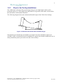
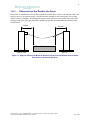
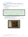
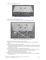
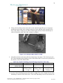
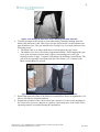
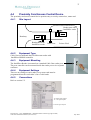
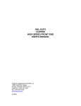
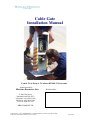
19
5. Dig a conduit trench (100 mm wide and 200 mm deep) between:
• The master post hole and the entry point of the place where the access control
system(s) are to be installed (if required)
• AND/OR, the master post hole and location for the solar panel pole (if required)
• AND/OR, the master post hole and the location of the external power supply plug
pack (if required)
Note that in installations into asphalt or a concrete slab, the conduit may be replaced
with a slot cut in the pavement surface. In this instance, the electrical cables can be
held in place with mastic after being installed.
6. Using a gas burner to soften the PVC conduit, make a right-angled bend 500 mm from
the end of a length of conduit.
7. Place this conduit in the trench to correspond with the slot in the master post
baseplate. Note that when the master post is viewed from the front, the cables should
enter the post 80 mm to the right of the post centreline. Wedge the conduit in place so
that the 500 mm straight section is pointing directly upward.
Figure 3-2: Conduit in Post Hole
8. Run a string line through all the conduit to be laid.
9. Using PVC adhesive, attach the required conduit, along the trench to the entry point or
weatherproof gate control box.
10. Place four M20 nuts on the master post bolt cage, one to each threaded section. Screw
these nuts down until about 50 mm of thread is showing on each section.
11. Place a bolt cage levelling board over the threads and place another nut on each
thread. Screw these nuts down until the top of each nut is 5 mm below the top of the
threaded section.
Document No. 13-01 (CONFIDENTIAL – Matilda Products Limited Copyright © 2004)
Cable Gate Installation Manual (Revision 0.2)
July 2004