1
FAST RADIO MODEM
ARD9900
Multi-Mode And Digital Voice Interface
Instruction Manual
AOR LTD.
Authority On Radio communications
Thank you for purchasing the AOR ARD9900 Multi-mode and Digital Voice Interface.
The ARD9900 is designed to convert your HF radio equipment to a multi-mode and digital voice
capable radio without performing any modifications to your transceiver.
Please read through this instruction manual and familiarise yourself with the operation of the
ARD9900.
We suggest you keep this instruction manual for future reference.
We believe the ARD9900 will become a powerful tool to enhance your communication capabilities.
AOR LTD.
Supplied Accessories:
The following items are provided in the box
Quantity
Speaker microphone ---------------------------------------------------------------------------------------- 1
PC interface cable -------------------------------------------------------------------------------------------- 1
Speaker cable ------------------------------------------------------------------------------------------------- 1
DC power cable ----------------------------------------------------------------------------------------------- 1
Microphone connector --------------------------------------------------------------------------------------- 1
Instruction manual (this booklet) -------------------------------------------------------------------------- 1
Optional accessories:
Memory Module ME-1 (necessary for SSTV and video functions).
Interface cables for most proprietary amateur transceivers.
Features:
z
z
z
z
z
z
z
z
z
z
Digital voice communications using existing analogue 2 way radios with encryption capability.
The ARD9900 uses the same audio frequencies (300 Hz ~ 2500 Hz) as
microphone audio to modulate the voice signal. This allows you to use an analogue
radio as a digital voice transceiver.
Digital voice communications in the Single Side Band (SSB) mode.
The automatic frequency clarifier function adjusts frequency drift automatically in the
SSB mode (approximately up to +/- 125 Hz).
Utilises an ODFM (Multi Carrier Modulation) circuit that is effective against Multi-path or Selective
Fading.
Automatic digital receive.
Automatic voice signal detector recognises the received signal as analogue or digital,
automatically switching to the appropriate mode.
Digital Slow Scan TV (SSTV). NB: Requires optional ME-1 memory module.
Built-in video capture function (NTSC or PAL depending on Country in which unit is purchased).
NB: Requires optional ME-1 memory module.
Compresses the signal into our original adaptive JPEG format.
Send and receive images in the Digital mode.
Built-in video output connector (NTSC or PAL depending on the country in which the unit is
purchased). Allows viewing of the picture on an external monitor.
Built–in high grade Vocoder (AMBE).
Utilising high-grade digital voice compression; delivers quality digital voice communications.
Built-in FEC error correction.
A powerful error correction circuit delivers stable and reliable communications.
Data communications on the HF band.
Data communication is possible on the HF (High frequency) bands at no extra cost.
(Speed may be limited by regulations in certain jurisdictions.)
Small and compact unit. Easy to operate.
Simply connect the ARD9900 to the microphone jack and speaker out jack of your transceiver.
No complicated or risky radio modifications are necessary.
z
Utilises a uniquely designed high performance DSP (Digital Signal Processor) engine.
z
Battery operation possible for field use.
Please note that it is a mandatory requirement within terms of the UK
Amateur Radio License that the call sign of the station is given at either
the beginning and end of each transmission, or at fifteen minute intervals
throughout the contact. This should be done by putting the ARD9900
back into analogue mode and making the announcement.
Precautions
To prevent fire, personal injury, or damage to the unit, please observe the following
precautions:
z
Do not attempt to adjust the unit unless instructed to do so by this manual.
z
Do not expose the unit to direct sunlight or place the unit close to heating appliances.
z
Do not place the unit in excessively dusty, humid or wet areas.
We are not responsible for any damage to the radio equipment due to improper
settings or interfacing.
We are not responsible for any loss of communications due to an unexpected change
of propagation or operating environment.
Table of Contents
Page
Supplied and optional accessories
Controls and functions
Front Panel
Rear Panel
Top Panel
Internal View
Bottom View
Interfacing the ARD9900
Connection to a Radio
Connection to a Microphone
Connection to a PC
Connection to a Power supply
Connection to an External speaker
Level Adjustment
Microphone level
Radio Input level
Code Setting
Master Key Code Setting
User ID Code Setting
Air Key Code Setting
Channel Switch Setting
Operation
Voice Communication
Digital Voice Communication
Analogue Voice Communication
Force Receive
Data Communication
Receive
Transmit
Digital Image Communication
Receive
Transmit
Type of Communications and their respective features
Communication Selection Guidance
Communication Mode Setting
Detailed functions of communication modes
Control Commands
Interfacing to a PC
Terminal Settings
Command format
Entering the System Management Screen
Operator’s Command List
Operator’s Command Details
Command List for the System Manager
Command Details of the System Manager
Specification
1
5
5
7
9
9
10
11
11
11
12
12
12
12,13
12
13
14
14
14
14
15
16
16
16
16
16
17
17
17
17
17
17
18
19
20
22
24
24
24
24
25
26
26
29
29
34
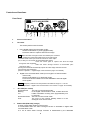
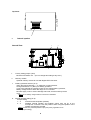
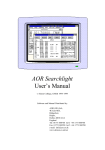
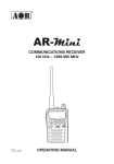
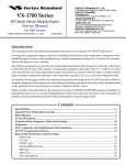
Controls and functions
Front Panel
FAS T R AD IO M O DEM
ARD 9 9 0 0
10101
4 56
23
POWER
a
TX
b
a.
Power on/off switch
b.
TX switch
BUS STA
c
SP
d e
C DE
Max
AB
Min
›•
7 9
F01
b•
MIC
MODE CHAN OVER
f
g
h
i
j
This switch performs two functions:
1. In the Digital Image Communication mode:
Set the mode switch to [10101] (digital mode).
Press this switch to capture and send an image.
Note: When the Video Through Function is activated (AVT command
is ON), pressing this switch will enable output of the video signal
connected to the Video Input to also be sent to the video output
port, so that you can monitor the transmitted video image.
Press this switch again to capture and send the image
through the radio equipment.
When the Video Through Function is de-activated (AVT
command is OFF),
pressing this switch will automatically capture the video image and then transmit
it through the radio equipment.
(Refer to: Operation -- Digital Image Communication at page 16 for details.)
2.
Digital Voice Communication mode (non encryption or fixed scramble
code mode)
Set the mode switch to [~] (analogue mode).
Press and hold this switch to force the ARD9900 to decode digital
voice signals.
Caution: Frequency tolerance for both parties must within the range of +/- 125 Hz.
(Refer to Operation -- Digital Voice Communication “force receive” on page 16 for details).
c.
Bus LED (two colour)
Illuminated red
The unit is in the transmit mode.
Blinking
In the digital communication mode, it blinks while the
red
header information is being sent (approximately one
[1] second).
Illuminated Green The unit is in the receive mode.
Unlit
The unit is in the receive standby mode or in the
analogue voice receive mode.
d.
Status LED (STA LED) (orange)
Lit when unsent data remains in the memory.
It is illuminated when the Video Through Function is activated in digital video
communication mode.
It is not lit when Video Through Function is deactivated by the dedicated
command (AVT_OFF) using the PC because the TX switch then activates a
sequential function of capturing and transmitting the data.
.
e.
Speaker volume adjustment
Adjustment for the internal speaker output level (or the external speaker output level
when one is connected).
f.
MODE LED (Operation Mode LED)
Indicates the current operation mode:
Illuminated green ------------------------Illuminated red --------------------------Illuminated orange-----------------------Not illuminated ----------------------------
g.
Digital voice mode
Analogue voice mode
Data communication mode
Digital image communication mode
CHANNEL switch
Select preloaded encryption code.
(Refer to: Channel Switch Setting on page 15 for details.)
h.
OVER-LED
Lit when the microphone input is overloaded (too high).
A proper microphone input level will cause the LED to flash from time to time
when speaking into the microphone at a normal level.
The microphone level can be adjusted with the microphone level controller.
(Refer to: Level Adjustment on page 12 for details.)
In addition, the OVER-LED operates in receive mode as an input level indicator:
To set the optimum level of audio from the transceiver (crucial for good decoding of
digital signals), the OVER-LED operates as an input level indicator in receive mode in
the following ways:
Operation of input level indicator (transceiver squelch control fully open):
Input level indicator flashes whilst receiving
Input level indicator extinguished
Input level indicator is solidly lit
Input level is too low
Input level is optimally set
Input level is too high
NB:
When the squelch is closed on the transceiver the OVER–LED will flash
continuously indicating that no signal is being fed to the ARD9900.
i.
j.
Mode switch
Selects the Digital voice mode [10101] or the Analogue voice mode [~].
When the Analogue voice mode [~] is selected, ordinary analogue voice
communications will be made.
In the receive mode however, the ARD9900 will automatically detect the
mode of the incoming signal and decode signals accordingly.
The LED indicates the respective operation mode.
Microphone connector
Connect the supplied microphone to this connector.
Below are the pin assignments of the connector:
1. SPEAKER OUTPUT -2. BIAS ---------------------3. GND ---------------------4. TX-------------------------5. D/A ------------------------
6. MIC PTT -----------------
Monitor output signal available at this pin.
Power source for an electret condenser type of
microphone. (5V DC through 2.2K Ohm resistor).
Chassis ground.
Taking this pin to the ground will enable the transmit mode;
the same as operating the TX switch on the front panel.
Taking this pin to the ground will force the unit into the
digital voice communication mode. When this pin is left
open, the operation mode will be set by the mode switch
on the front panel.
PTT (Push To Talk) input.
7. MIC GND ---------------8. MIC IN --------------------
Microphone ground signal.
Microphone signal input.
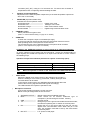
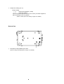
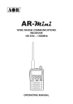
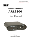
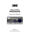
Rear Panel
AOR,LTD.
OUT
VIDEO
-
+
SP
IN
IN
k
l
DC IN
OUT
m
RADIO
n
o
p
q
r
k. Communication Connector (mini DIN 8 pin)
Connector to PC (RS-232C)
Pin Number
1
2
3
4
5
6
7
8
Shell
Signal
TX
DTR
DSR
GND
RX
RTS
CTS
NC
FG
Signal Direction
ARD9900----->PC
ARD9900----->PC
ARD9900<-----PC
GND
ARD9900<-----PC
ARD9900----->PC
ARD9900<-----PC
No Connection
Frame ground
Baud Rate
Data bit
Start bit
Stop bit
Parity
Synchronisation
Flow control
9600
8
1
1
None
Asynchronous
Hardware
l.
VIDEO - IN connector
NTSC or PAL depending on country of purchase, 1V p – p, 75 ohm (RCA type
connector).
Connect a video signal source such as a video camera, VCR output, etc.
m.
VIDEO – OUT connector
NTSC or PAL depending on country of purchase 1V p – p, 75 ohm (RCA type
connector).
Connect a video monitor to this connector to monitor a received image or a picture to be
sent.
n.
RADIO Connector
The pin connections of this port conform to those used by the manufacturer Adonis and
many of the current amateur radio transceivers are catered for by ready made cable
assemblies available from AOR. Otherwise, use the supplied 8-pin connector to connect
the ARD9900 to your radio equipment.
You will need to wire a cable according to the microphone connector specifications of your
radio.
Below are the pin assignments of the connector on the ARD9900:
Pin number
1
2
3
4
5
6
7
8
Signal
MIC GND
MIC OUT
PTT
GND
NC
NC
GND
NC
Details
Microphone ground
Microphone Output
PTT (Push To Talk) output
PTT ground
No connection
No connection
Ground
No connection
Caution: MIC GND and GND must not be connected together in the ARD9900
connector, or RF feedback will result.
o.
SP IN Connector (3.5 mm mono jack)
Connect to the radio equipment’s external speaker jack.
(Input level: 0.5 V – 5 V p-p)
p.
SP OUT Connector (3.5 mm mono jack)
Connect an external speaker to this jack (the internal speaker will be disabled).
q.
DC IN Connector (EIAJ Type 4)
Connect to a regulated power supply. (10.7 ~ 16.0 V DC, Centre pin – positive)
For lower voltage battery operation, set the internal jumper JP 9 for battery
operation, and then connect external batteries (see page 9 for details).
Caution: If you have changed the internal jumper for low-voltage battery operation, the
battery voltage must be within the range of 5.6 ~6.5 VDC.
(DO NOT apply 12.0V or severe damage will result, and the warranty will be void!)
Note: No low battery voltage detector is built-in the ARD9900.
r.
FG
Frame Ground
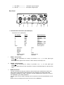
Top Panel
s
s.
Internal speaker
Internal View
v
w
x
u
t
t.
Factory setting jumper (JP 8)
Must be set between 2-3. (Do not change this setting at any time.)
u.
Memory module
Optional memory module for use with Digital SSTV functions.
v.
Battery operation selector (JP 3)
Place the jumper between 1 – 2 (NOR) for normal operation.
Change it between 2-3 (BATT) for battery operation.
If you have changed the internal jumper for low-voltage battery operation,
battery voltage must be within the range of 5.6 ~6.5 VDC.
DO NOT apply 12.0V or severe damage will result, and the warranty will be
void!
Note: No low battery voltage detector is built-in the ARD9900.
w.
Internal speaker setting (JP 6)
Jumper setting
1 -- 2
Activates internal speaker (default).
2 -- 3
Disables internal speaker and enables output from pin #1 of the
microphone connector. Use this position when using the speaker of the
speaker microphone provided.
Note: The SP OUT (external speaker output) has priority regardless of the
above jumper setting.)
x. Output level setting (JP 10)
Jumper setting
1-2
Normal level (default) (LOW)
2-3
High level (HIGH)
If the microphone output level is too low to drive your radio equipment,
place the jumper in the 2-3 position.
(Refer to: Radio Input Level setting on page13 for details.)
Bottom View
y
y.
Microphone output (Radio Input) level
(Refer to setting level adjustment on page 13 for details)
Interfacing the ARD9900
Connection to a Radio
Before using your ARD9900, you will first need to wire the cable between your radio
equipment and the ARD9900. For convenience the connector on the ARD9900 is
wired to a standard specification used by the manufacturer Adonis.
ARD9900
Radio Equipment
Radio Connector
1
2
3
4
5
6
7
8
MIC GND
MIC IN
PTT IN
PTT GND
GND
EXTERNAL SPEAKER OUT
GND
MIC GND
MIC OUT
PTT (H)
PTT (l)
N.C.
N.C.
GND
N.C.
SHELL
SP IN Connector
Signal
GND
An 8-pin microphone connector for the ARD9900 is included to enable you to make your own
connection cable, however you will need to supply and prepare your own microphone
connector for your radio equipment. Alternatively, various ready-made cables to suit most of
the current transceivers on the market are available from AOR.
Below are the pin assignments of the 8-pin RADIO connector on the rear panel
of the ARD9900.
Pin number
1
2
3
4
5
6
7
8
Signal
MIC GND
MIC OUT
PTT (H)
PTT (L)
NC
NC
GND
NC
Details
Microphone ground.
Microphone output.
PTT (Push To Talk) output.
PTT (Push To Talk) ground.
No connection.
No connection.
Ground.
No connection.
Note: MIC GND and GND must not be connected together in the ARD9900 connector,
or RF feedback will result.)
Connection to a Microphone
A speaker microphone is included with your ARD9900. However, if you wish to use
your own microphone with the ARD9900, you may do so by wiring your microphone to
correlate with the input socket of the ARD9900. Below are the pin assignments of the
Microphone connector of the ARD9900:
Pin
1.
Function
Speaker output
2.
BIAS
3.
4.
GND
TX
5.
D/A
6.
7.
8.
PTT
MIC GND
MIC IN
Description
Monitor output signal is present at this pin when the
internal speaker Jumper is set to 2 – 3.
Power source for an electret condenser type of
microphone. (5V DC through a 2.2K Ohm resistor).
Chassis ground .
Taking this pin to the ground will enable transmit. (The
same as the operation of the TX switch on the front
panel.)
Taking this pin to ground will force the ARD9900 into
the Digital voice communication mode. When this pin is
left open the operation mode will be set by the mode
switch on the front panel.
PTT (push to talk) input.
Microphone ground signal.
Microphone signal input.
Connection to a PC
A PC interface cable is included with the ARD9900.
Parameter settings can be made by using terminal software such as Windows HyperTerminal.
(Refer to: Control Commands on page 24 for details.)
Connection to a Power Supply
To operate your ARD9900, use a regulated power supply.
The operating voltage must be within the range of 10.7 ~ 16.0 V DC (current
requirement approximately 200mA).
A DC power cable is included with the ARD9900 following the standard convention:
RED
BLACK
Positive ( + )
Negative ( - )
If you have changed the internal jumper for low-voltage battery operation, the
voltage used must be within the range of 5.6 ~ 6.5 VDC.
DO NOT apply 12.0 V with the jumper in this position or severe damage will
result, and the warranty will be void!
Note: There is no low battery voltage detector built into the ARD9900.
Connection to an External Speaker
If you wish to use an external speaker, connect it to the SP OUT jack. This will also disable the
internal speaker.
Level Adjustment
Microphone Level
The microphone level has been properly adjusted at the factory for use with the microphone
provided, therefore no further adjustment is needed for normal operation.
If you wish to use your own microphone rather than the included one, you will need to wire
your microphone connector to match the pins of the ARD9900, and then adjust the microphone
level as described in the following steps:
1. Connect your microphone to the Microphone connector on the ARD9900.
(Note: The microphone cable to the radio MUST be unplugged at this time.)
2. Select the mode switch (i) to the digital [10101] position.
3. Select the 0 (zero) transmitting channel [CHAN].
4. Turn ON the ARD9900 while pressing the TX switch. The status LED will blink orange
indicating the ARD9900 is now in the microphone level-adjusting mode.
5. Now speak into the microphone whilst pressing PTT button. Rotate the transmitting
channel [CHAN] control clockwise until the [OVER] LED is lit on speech peaks.
6. After you have chosen the appropriate microphone level, press TX switch while pressing
PTT button. The TX LED will illuminate orange and the new microphone level will have
been memorised.
7. Release the PTT button and select Mode switch to analogue (~) position.
8. The microphone level adjustment in Analogue mode is not normally required however, if
the audio signal level is weak at the distant station, you can carry out the same process
from 1 to 4 above even though it is for analogue mode. Pressing TX switch while pressing
the PTT button will confirm the new setting as before.
Turn the power OFF on the ARD9900 to terminate the microphone level-adjusting mode.
Radio Input Level
Perform the following steps to obtain the correct level of input for your radio equipment:
connect the microphone to the ARD9900, and then connect the ARD9900 to your radio
equipment. Finally, Connect the ARD9900 to a power supply and turn the output level
adjustment on the bottom of the ARD9900 fully counter clockwise. Now:
1.
2.
3.
4.
5.
6.
Turn the power on to the ARD9900.
Turn the power on to your radio equipment.
Set the mode switch to [10101] (digital mode).
Press the [PTT] switch of the microphone to transmit from the radio equipment.
Adjust the microphone gain of the radio equipment until the ALC function just activates.
If the microphone gain is too low, readjust the output level on the bottom of the
ARD9900 (See page 8 for adjustment location).
7. If the microphone gain is still too low after adjustment, turn off the ARD9900, remove the
top cover and set the output level setting jumper (JP 10) to the high level position [2-3]
and repeat the above procedure (See page 9 for jumper position).
Code Setting
Master Key code setting
The master key code is a password to allow the authorised operator access to the system
management settings for maintenance. It also forms the key onto which the encryption
algorithm is applied.
To prevent unauthorised tampering with the system code settings and possible damage to the unit
from incorrect code entry (see warning below), the master key code MUST be changed to your own
code prior to operation and the new code should be noted and securely stored.
To change the Master Key code, type the [AMS] command using a terminal program on a PC.
cmd>AMA_123456789012 [CR]
CMD>AMA OK
CMD>AMS_************ [CR]
Å Enter the factory default code. ( _
: space key)
(Response from PC)
(Enter a new master key code.)
Note : The master key code consists of 12 digits of numeric code (0 ~ 9). Default code: 123456789012
(Refer to: Control commands on page 24 for details.)
Warning!
The master key code MUST be kept in a secure place. Without a master key
code no code changes can be made.
If you made an entry error during the initial code setting, correct it under the Master Key code entry
screen before exiting. Once you exit from the master key code setting screen with an
incorrect/unknown code, neither you nor the factory will be able to change it!
User ID code Setting
The User ID code is a unique code set by you to identify your own ARD9900 for use with the digital
squelch mode.
To change the ID code, first type the [AMA] command to allow entry into the
Data management Menu:
cmd>AMA_ ************ [CR] Å Enter the master key code
CMD>AMA OK
(Response from PC) note that the command prompt is now upper
case to indicate you are in the System Management screen.
(Enter a new user ID code.)
CMD>AUI_***** [CR]
Note : The user ID code consists of 5 digits of numeric code (0 ~ 9)
Default : 77777
(Refer to: Control command on page 24 for details.)
Air Key code Setting
The Air Key code is a string of encryption code information that is attached to the beginning
of the transmitted data packet.
To set the Air Key code, first type the [AMA] command to allow entry into the
Data management Menu:
cmd>AMA_ ************ [CR]
CMD>AMA OK
CMD>AAK_**** [CR]
Å Enter the master key code
(Response from PC)
(Enter a new Air Key code.)
Note : The Air Key code consists of 4 digits of numeric code (0 ~ 9)
Default : 0000
(Refer to: Control commands on page 24 for details.)
Channel Switch Setting
There are 16 different channel settings for the ARD9900. By simply rotating the channel
switch on the front panel of the ARD9900 to the desired setting, a pre-programmed
encryption mode can be easily recalled from the memory.
To set the Channel Switch setting, first type the [AMA] command to gain entry into the
data management menu.
Rotate and select the desired channel switch position (0 ~ F).
cmd>
(Stand by for command)
cmd>AMA_ ************ [CR]
(Enter the master key code.)
CMD>AMA OK
(Response)
CMD>AAK_**** [CR]
(Enter a new Air Key code.)
Note: The Air Key code consists of 4 digits of numeric code (0 ~ 9)
Default : 0000
(Refer to: Detailed function description on page 22 and Control Commands on page 24 for details.)
CMD>ACP [CR]
(Display current channel )
CH: $ _ ID: !!!!!! _ NM: @@@@@ _ MD : &
(Setting for the current channel data)
CMD>
(Standby for command)
CMD>ACP _ !!!!! _ @@@@@ _ XX ZZ (Set current channel data)
CH : 1 _ !!!!! _ NM : @@@@@ _ MD : &
(Response)
Note : [$] , [!], [@] , [&], [X], [Z] - - - Parameters]
$
Channel number (Selected by the front channel switch)
_ Space
(Press the space key of the PC keyboard)
!!!!! Other party’s ID (Other party’s unique ID i.e. their AUI code)
@@@@@
Netmask
(Current Netmask)
F (1): Netmask valid 0: Netmask invalid
&
Communication mode (Displays the communication mode on the channel)
0 : Non encryption mode
This is how the modes are displayed under the
1 : Digital squelch mode
ACP command, they cannot be entered as 1 digit
codes like this, they are entered as part of the
setting mode and algorithm setting parameters
2 : Fixed encryption mode
below (XXZZ)
3 : Random encryption mode
!!!!!
Other party’s ID
I D : 00000 ~ 99999
@@@@@ Netmask
(Set Netmask
valid/
invalid)
Enter “1” or “0” to each digit.
1 : ID digit valid
0 : ID digit invalid
(Set other party’s unique ID i.e. their AUI code)
The net mask serves to identify how much of the other party’s unique
ID i.e. AUI code is necessary for communication to be achieved. If you
enter an ID of 12345 and a net mask of 11100 only the first three digits
will be required to match for communication to take place. This means
you can arrange a net communication if all members AUI identifier
begins with the numbers 123.
Note : On the PC screen, “1” will be displayed as “F.”
X X Setting mode 80 : Non encryption mode
00 : Fixed encryption mode
40 : Fixed airkey random encryption mode
50 : Random encryption mode
ZZ
Algorithm
Set communication algorithm
Note : When the communication mode is set to Non Encryption mode (80), then the algorithm must be set to
either[ 0 0 ] or [ 01] .
00 : Non encryption mode (default)
01 : Digital squelch mode
Note : When the communication mode is set to Fixed Encryption
mode (00) or Random Encryption mode (40, 50), then the
algorithm must be set as follows:
00 ~ 79 : Fixed Scramble Code
80 ~ 99 : Variable Scramble Code
(every 20 mS)
Note : When you execute the ACP command, it will not display detailed communications settings or algorithm
values. If you wish to check detailed settings, use the ADS command in the system management mode.
Typical example of channel setting entry for with the ARD9900 set to channel 1:
ACP_12345_11100_8001<CR>
When you then type ACP<CR> at the command prompt, to check this, it will return the following:
CH: 1 ID:12345 NM:FFF00 MD:1 indicating that channel 1 has been set for a remote ID of 12345
where only a match on the first three digits is required and the digital squelch is set to on. The
fact that the number 8001 was used shows that a none encryption mode has been selected and
the digital squelch is set to on.
For details of all the communication modes possible, see page 19 communication Selection
Guidance.
Operation
Note: All adjustments must be properly performed before operation.
Voice Communication
Your ARD9900 is capable of digital or analogue voice communications. In the
receive mode, the ARD9900 will automatically recognise the type of communication,
and set itself to the appropriate mode. In the transmit mode, the desired operating
mode can be selected by using the front panel Mode switch.
Digital Voice Communication
Set the mode switch [10101 ~ ] upward to the digital mode position [10101].
Rotate the Channel switch on the front panel to select the desired communication
code setting.
Press and hold the PTT switch on the microphone. The STA (Status) LED will flash for
about 0ne (1) second while sending a data header signal.
When the LED stops flashing, speak into the microphone normally.
Analogue Voice Communication
Set the mode switch [10101 ~ ] downward to the analogue mode position [~] .
Press and hold the PTT switch on the microphone, and speak into the microphone
normally.
Note: The front Channel switch setting will be ignored in the Analogue Voice Communication
mode.
Force Receive
While in the Non Encryption mode (80) or Fixed code encryption mode (00) if a
Header signal is not properly received during communication, you can “force” the
ARD9900 to receive in the digital voice mode under following conditions:
z
z
z
The communication mode is in the Non Encryption mode (80) or the
Fixed Encryption mode (00).
The frequency difference between both parties is within +/- 125 Hz.
Both parties have the same communication settings.
[Procedure]
1.
2.
3.
Set the mode switch [10101 ~ ] downward to the analogue mode position [ ~ ].
Press and hold the TX switch for about 5 ~ 10 seconds until an audio signal is
heard from the speaker.
Once an intelligible audio signal is obtained, release the TX switch.
Data Communication
Run a terminal software program such as Windows HyperTerminal to control the
ARD9900, and enter control commands.
[Refer to: Control Commands at page 24 for details.]
Two different types of data, ASCII or binary data can be used. Both data types can be mixed
as communication data.
Receive
Enter the command [ACO] to go into the converse mode. The valid received data will be
decoded and displayed on the PC screen. If received data is missing, (which may occur during
poor propagation conditions) “garbage” data may be displayed on the PC screen.
Transmit
Enter the command [ACO] to enter the converse mode then type text on the keyboard. When
you have finished, press the enter key.
NNNNNNNN [CR]
NNNNNNNN : ASCII character
[CR]:
Carriage Return
Note: Maximum data length is 2046 bytes per packet.
To send binary data, add [FE] (hexadecimal) as a header and footer to your data.
FE BBBBBBBBBBBBBBBB FE
BBBBBBBBBBBBBBB : Binary data
FE :
ID as a binary data
Note : If you need to insert the data [FE] in hexadecimal in the middle of the text, convert it into
two (2) bytes of hexadecimal data.]
FE
Æ
FD
Æ
FDD8
If you need to insert the data [FD] in hexadecimal in the middle of the text, convert it to
two (2) bytes of hexadecimal data.
FDDD
Note : Maximum data length is 2046 bytes per packet.]
At the receive side, the data will be automatically decoded and displayed on the PC screen.
If the [ALF] command is set ON, the LF (line feed) code will be added at the end of the
received data.
Digital Image Communication
Receive
When valid digital image data is received, it will be decoded and output as a video image from
the VIDEO OUT connector.
If received data is missing during a transmission, that portion will be displayed as invalid
(Like noise).
Transmit
When pin - 4 of the microphone connector is grounded, the ARD9900 starts sending an image.
When the Video Through Function is activated (AVT command is ON), pressing the TX switch
once will enable output of the video signal connected to the Video Input to be sent to the video
output port so that the video image can be checked before transmission. Pressing the TX
switch again will capture the image and then transmit it through your radio equipment. When
the Video Through Function is de-activated (AVT command is OFF), pressing the TX switch
will automatically capture the video image and then transmit it through the radio equipment. A
Progress indicator will display on the monitor during image transmission.
Types of communication and their respective features:
Encryption Method
•
The Master key and algorithm is used to create the encryption table therefore the Master
key and algorithm must be set to the same values for both the transmit and receive units.
•
The actual encryption code is selected from the encryption table by the Air Key.
In the Fixed Encryption mode (Flag : 00), the transmit data does not contain the Air Key. To
decode the received signal then, both parties must set the air key to the same value. Therefore
the Air Key must be obtained in advance, to select the encryption code and decode the
signals.
•
In the Random Encryption Mode 1, 2 (Flag : 40), the Air Key selected at the transmit end is sent
along with transmit data. At the receive end, the received data will be decoded by selecting
from the encryption table using the received Air Key, therefore matching Air Keys are not
required between parties.
•
In the Random Encryption Mode 3, 4 (Flag : 50), the random number coded Air Key is sent
along with transmit data. At the receive end, the received data will be decoded by selecting
from the encryption table using the received Air Key so again matching Air Keys are not
required.
•
Additionally, in the Random Encryption Mode 2, 4 (algorithm 80 – 99), the scramble function is
enabled and the encryption code will be changed in every 20 mSec. At the receive end, the
received data will be decoded by changing the encryption code in every 20 mSec. in
synchronisation with the original Air Key so again matching Air Keys are not required.
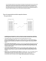
With reference to the points above, choose the most appropriate communication mode from the table
below:
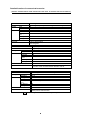
Communication Selection Guidance
The following is a list of communication modes for the ARD9900. Choose the most suitable
communication mode for your application. The factory default setting is the non encryption
mode (Communication mode : 0).
Communication
Mode
Non Encryption
Mode
Digital Squelch
Mode
Fixed Encryption
Mode
Random
Encryption Mode
1
Random
Encryption Mode
2
Random
Encryption Mode
3
Random
Encryption Mode
4
Mode
Flag
Setting
Algorithm Encrpt. SQ
Function
Air Key at
RX
Air Key TX
Scramble
0
80
00
No
No
---
---
---
1
80
01
No
Yes
---
---
---
2
00
00-79
Yes
No
Pre-set
No
Fixed
3
40
00-79
Yes
Yes Received
Air Key
Pre-set
Fixed
3
40
80-99
Yes
No
Pre-set
Variable
3
50
00-79
Yes
Yes Received
Air Key
Random
number
Fixed
3
50
80-99
Yes
Yes Received
Air Key
Random
number
Variable
(Note: Encrpt: Encryption.
Received
Air Key
SQ: Squelch RX : Received transmission )
•
When the flag value is set to [80], enter the algorithm value for either [00] or [01] only. No other
value must be entered.
•
When the flag value is set to [00], enter algorithm value between [00] to [79]. No other value must
be entered.
•
The scramble function is valid only in the random encryption mode when the algorithm is set
Between flags [80 – 99]. During the communication, the encryption code will be changed every 20
mSec according to the algorithm.
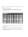
Communication Mode Setting
The communication setting is set into discrete channels.
[Procedure]
1. Using the AMA command, enter the Master Key Code to gain access to the System
Management Screen.
2. Select the desired channel on the front panel.
3. Using the ACP command set the desired communication mode setting.
To verify details of the setting, use the ACP command.
ACP [CR]
To verify details of the communication channel, use the ADS command.
ADS [CR]
[Example]
CH : 5
ID : 12345
NM : FFFFF
MD : 0
ACP [CR]
CH: 5 ID : 12345 NM : FFFFF MD : 0
Channel 5 is selected
Destination ID is set to 12345
Displays the nest mask setting. [ F] is indicating the digit is valid.
Communication mode is [ 0 ] (Non encryption mode entered as 8000).
This would have been entered as:
ACP_12345_11111_8000
Checking with the ADS command would reveal the following:
Flag:80
Algorithm:00
AirKey:0000
UserID:77777
CH:8 ID:12345 NM:FFFFF MD:0
None encryption mode
Digital squelch off
Air key (previously set with AAK command)
Your unique user ID set with the AUI command
Reported back information from ACP setting
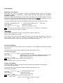
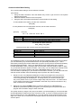
The ARD9900 provides 16 channels (A~F, 0~9) and has a digital squelch system that enables
you to avoid hearing any transmissions that are not specifically intended for you. This is
achieved by matching the remote stations AUI (or part of it) using the ID command and setting
the appropriate NETMASK. This is only applicable to those modes that have a squelch
function attributable to them; referring to the communication selection guidance table on page
19, you will see that this is applies to modes 1 and 3 only. You can assign each channel for the
remote ID of your chosen contacts, and use the NETMASK feature to set up group
communications. Depending on your desired communication scenario, you can then select the
channel number suitable. Take the following steps to perform the channel setting:
1.
Decide on your own individual identification number and program this using the AUI
command. Type AUI at the System Manager command prompt, press return and the
current 5 digit setting will be displayed. To change this to your chosen number type
AUI_xxxxx (where xxxxx is your chosen 5 digit code) and press return. The AUI number
is now saved in the memory of the ARD9900. Note that only numbers not letters or any
other characters are acceptable.
2.
Select the TX channel [CHAN] where you want to assign the ID, NETMASK and
SQUELCH parameters (and any encryption you wish) using the front panel switch and
program the information using the ACP command.
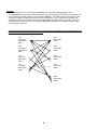
The system works by using the ID (AUI) of the station you are attempting to communicate with,
and the NETMASK to define how much of that ID is used. If you are contacting someone with
an ID of 12345 and you use a NETMASK of 11111 this means you are requiring all five of the
digits of the other user to match before their digital squelch will be broken and communication
can take place.
Example
Consider setting an ID of 12345 and a NETMASK of 11100 with the digital squelch set on.
The NETMASK you have set enables contact with any remote station that contains the numbers 123
in the first part of the AUI code set on the remote ARD9900. This means that someone with an AUI
of 12345 or 12366 or 12367 etc will all hear your transmission. If you consider this carefully, this
enables you to have an exclusive net by using appropriate AUI codes within your group. You have
16 channels that can be set with varying ID and NETMASK settings so it is possible to store many
communication scenarios.
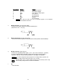
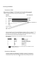
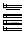
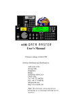
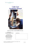
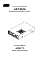
The diagram below illustrates the types of communication possibilities using the DCS and the
ID of the remote stations you are contacting:
Tx1
ID:12345
NM:FFF00
MD:1
Rx1
AUI:12345
MD:1
Tx2
ID:12345
NM:FFFF0
MD:1
Rx2
AUI:12355
MD:1
Tx3
ID:12345
NM:FFFFF
MD:1
Rx3
AUI:12348
MD:1
Tx4
ID:12345
NM:FFFFF
MD:0
Rx4
AUI:13345
MD:1
Rx5
AUI:12345
MD:0
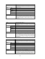
Detailed function of communication modes
[Caution: Communication mode must be set to the same for transmit and receive stations.]
Mode
Features
Setting
Functions
Mode Code
Remarks
Mode
Features
Setting
Functions
Flag
Algorithm
Encryption
Squelch
Air Key at RX
end
Air Key TX
Rolling Code
Non encryption mode
Non encryption (factory default setting). Force receiving available.
80
00
No
No
------0
Factory default setting
Non encryption
Flag
Algorithm
Encryption
Squelch
Air Key at RX
end
Air Key TX
Rolling Code
Mode Code
Remarks
Mode
Features
Setting
Functions
Mode Code
Remarks
Flag
Algorithm
Encryption
Squelch
Air Key at RX
end
Air Key TX
Rolling Code
Digital Squelch mode
Digital Squelch is available.
80
01
No
No
------1
Squelch will open or close by comparing the destination ID
and value of the net mask with the receiver’s user ID.
Fixed Encryption mode
Effective against noise. Force receiving is available.
00
00-79
Yes
No
Use the Air Key set at the receive end
No
Fixed
2
Air Key, Flag, Algorithm must be set to the same for both
parties prior to communication
Note: A value of algorithm must be set between [00 ~ 79].
Mode
Features
Setting
Functions
Flag
Algorithm
Encryption
Squelch
Air Key at RX
end
Air Key TX
Rolling Code
Mode Code
Remarks
Mode
Features
Setting
Functions
Flag
Algorithm
Encryption
Squelch
Air Key at RX
end
Air Key TX
Rolling Code
Mode Code
Remarks
Mode
Features
Setting
Functions
Mode Code
Remarks
Flag
Algorithm
Encryption
Squelch
Air Key at RX
end
Air Key TX
Rolling Code
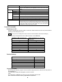
Random Encryption mode 1
Communication can be made with the station that has Flag
40 or Flag 50. (The Master key and algorithm must be set to
the same value.)
40
00-79
Yes
Yes
Use the Air Key in the transmit data
Send the pre-set code from the transmit end
Fixed
3
Once the mode code and algorithm is set to the same at both
ends, communication can be made with the station that has
Flag 40 or Flag 50. Since the Air Key is sent from the transmit
end, It is not necessary to have the same Air Key at the
receive end.
Random Encryption mode 2
Communication can be made with the station that has Flag 40
or Flag 50. (The Master key and algorithm must be set to the
same value.)
40
80-99
Yes
No
Use the Air Key in the transmit data
Send the pre-set code from the transmit end
Will change in every 20 mSec according to the algorithm
3
Once the mode code and algorithm is set to the same at both
ends, communication can be made with the station that has
Flag 40 or Flag 50. Since the Air Key is sent from the transmit
end, It is not necessary to have the same Air Key at the
receive end. The code will be scrambled and will change in
every 20 mSec.
Random Encryption mode 3
Communication can be made with the station that has Flag 40
or Flag 50. (The Master key and algorithm must be set to the
same value.)
50
00-79
Yes
Yes
Use the Air Key in the transmit data
Send the random coded Air Key from the transmit end
Fixed
3
Once the mode code and algorithm is set to match,
communication can be made with the station that has Flag 40
or Flag 50 since the Air Key is sent from the transmit end. It is
not necessary to have the same Air Key at the receive end.
The code will be scrambled and will change every 20 mSec.
Mode
Features
Setting
Function
Random Encryption Mode 4
Communication can be made with the station that has Flag 40 or
Flag 50. (The Master key and algorithm must be set to the same
value.)
50
80-99
Yes
Yes
Use the Air Key in the transmit data
Flag
Algorithm
Encryption
Squelch
Air Key at RX
end
Air Key TX
Send the random coded Air Key from the transmit end
Rolling Code
Mode Code
Remarks
Will change in every 20 mSec according to the algorithm
3
Once the mode code and algorithm is set to the same at both ends,
communication can be made with the station that has Flag 40 or Flag
50. Since the Air Key is sent from the transmit end It is not necessary
to have the same Air Key at the receive end. The code will be
scrambled and will change every 20 mSec.
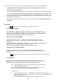
Control Commands
Interfacing to a PC
Using the supplied PC interface cable, connect the COM connector at the rear panel (marked
[10101] ) to the serial port of a PC.
NOTE: Be sure your PC’s serial port is active. Check for correct hardware and software settings!]
Below are the pin assignments of the COM connector of the ARD9900:
ARD9900 COM connector pin)
Serial connector of a PC (DSub 9-pin)
Pin
2
6
4
5
3
8
7
1
GND
Pin
1
2
3
4
5
6
7
8
GND
Terminal Settings
Communication Speed:
Data Length
Start Bit
Stop Bit
Parity:
Flow Control:
Local Echo
Specifications:
9600 bps
8 bit
1
1
None
Hardware
None
RS-2332C
Command Format
Run a terminal software program such as Windows HyperTerminal, and then turn the power of
the ARD9900 on.
The following message should appear on the PC screen:
cmd>
This indicates the ARD9900 is ready to accept commands from the PC.
Each command consists of three (3) alphabetical characters:
cmd>CCC_NN [CR]
CCC:
_
NN:
[CR]:
Command (Must be in upper case)
Space
Parameter
Carriage Return
Entering a command without a parameter will display the current parameter (value)
setting.
cmd>CCC[CR]
If an invalid parameter or command is entered, the ARD9900 will respond as follows:
cmd>
?
cmd>
Entering the System Management Screen
Using the AMA command with the master key code, you can enter the System Management
Screen. To let you know that you are in the System Manager Screen, the command prompt
changes from lower to upper case:
cmd>AMA_************ [CR]
( _ : space key)
CMD>
(Å Enter the master key code.)
(Response from PC)
Note : The master key code consists of 12 digits of numeric code (0 ~ 9).
The factory default is 123456789012]
Warning !
The master key code MUST be kept in a secure place. Without the proper master key code,
no System Manager specific code changes can be made. In addition, it is the number on
which the encryption algorithms base their encryption so as the system manager, you will
need to be aware of the number to arrange communications within your communication group.
If you made an entry error whilst changing the Master Key
Code, correct it before pressing the return key. If you exit
from the master key code setting screen with an
incorrect/unknown code neither you nor our factory can
change it.
Operator’s Command List
Command
AAQ
ACD
ACN
ACO
ACS
ADC
ADS
AMA
ATX
AVR
Function
Send VIDEO In signal to VIDEO OUT (to a monitor screen)
Capture image into memory of the ARD9900
Display the last received sender’s ID
Display the last received net mask
Enter the Converse mode
Display the last received sender’s ID
List the current commands
Display current settings
Entering to the System Management Screen
Send digital image
Display the current firmware version
Operator’s Command details
AAQ
Function
Default
Format
Parameter
Details
Example
Send VIDEO In signal to the VIDEO OUT (to the monitor screen)
Capture image into memory of the ARD9900
None
AAQ {0 / 1} [CR]
1: Send VIDEO In signal to the VIDEO OUT (to the monitor
screen)
0: Capture image into memory of the ARD9900
While AVT command is OFF, [AAQ 0] will be accepted.
Entering AAQ[CR] will respond with the current status.
AAQ ON --- Video signal is passed to the VIDEO OUT port
AAQ OFF --- Video signal is not passed to VIDEO OUT
AAQ_0 [CR]
ACD
Function
Default
Format
Parameter
Details
Example
Display the last received sender’s ID
12356
ACD [CR]
None
Display the last received sender’s ID
ACD [CR]
ACN
Function
Default
Format
Parameter
Details
Example
Display the last received net mask
FFF00
ACN [CR]
None
Display the last received net mask
ACN [CR]
ACO
Function
Default
Format
Parameter
Details
Example
Enter the Converse mode
None
ACO [CR]
None
Change from the command mode (displaying [cmd>] on the
screen) to the converse mode.
In the converse mode, characters and/or binary data can be
sent.
To return to the command mode, press the “C” key while holding
the “Ctrl “(control) key.
ACO [CR]
ACS
Function
Display the last received sender’s ID
Default
Format
Parameter
Details
Example
12356
ACS [CR]
None
Display the last received sender’s ID
ACS [CR]
ADC
Function
Default
Format
Parameter
Details
Example
List the current commands
None
ADC [CR]
None
List the current commands
ADC [CR]
ADS
Function
Display current settings
Default
Headerlen: 1.00
AFC = ON
Analogue : ON
UserID : 77777
CH : X ID : 00000 NM : 00000 MD : 0
X : Currently selected channel number
ADS [CR]
None
Display current settings
ADS [CR]
Format
Parameter
Details
Example
AMA
Function
Entering to the System Management Screen
Default key
Format
Parameter
Details
123456789012
AMA_ {000000000000 – 999999999999} [CR]
000000000000 - 999999999999
Entering the System Management Screen by using the master
key code.
AMA_123456789012 [CR]
Example
ATX
Function
Default
Format
Parameter
Details
Example
AVR
Function
Default
Format
Parameter
Details
Example
Send digital image
None
ATX [CR]
None
An image must be captured and stored into memory before it can
be sent.
ATX [CR]
Display the current firmware version
None
AVR [CR]
None
Displays the current firmware version
AVR [CR]
Command List for the System Manager
Note:
1. The following commands are available under the system management
screen only.
2 After any of the following commands have been changed, the ARD9900power must
be turned off, and then turned back on to reinitialise.
Command
AAK
ACP
ADC
ADS
AFC
AHL
ALF
AMS
APR
ARA
ATT
AUI
AVT
Function
Set an Air Key code
Set the transmit channel
Display the current commands
List the current channel settings
Set AFC on/off
Set the duration of the synchronous header signal
Adds the LF command when the [CR] key of the PC is pressed
Change the master code key
Reset the unit to the factory’s default setting
Select to monitor digital voice and analogue voice or analogue
only analogue voice
Set the output level of the ARD9900 to the radio
Set user ID
Activate/deactivate the video through function
Command details for the System Manager
AAK
Function
Set an Air Key code
Default
Format
Parameter
Details
Example
0000
AAK {0000 – 9999} [CR]
{0000 – 9999}
Set an Air Key code
AAK_1111 [CR]
ACP
Function
Default
Format
Parameter
Details
Set the transmit channel
CH : X
ID : 00000 NM : 00000 MD : 0
X : The current selected channel
ACP _ {00000 – 99999} _ {each digit 1/0} _ {80/00/40/50}{00 – 99}[CR]
00000 – 99999
Other party’s ID (numbers only, no other characters)
Number 1/ 0
Net mask setting
0 : Net mask / squelch invalid
1 : Net mask / squelch valid
(Note: the “1” will be displayed as “F” on the screen.)
80/00/40/50
Flag setting
80 : Non encryption communication mode
00 : Fixed encryption communication mode
40 : Random encryption communication mode 1 or 2
50 : Random encryption communication mode 3 or 4
Note : When the flag is set to [40], then the Random
encryption mode 1 or 2 will be selected according
to the value of algorithm.
When the flag is set to [50], then the Random
encryption mode 3 or 4 will be selected according
to the value of algorithm.
00 –99
Algorithm setting
When the flag is set to [80], the algorithm MUST be set to
00 (Non encryption mode) or 01(Digital squelch mode.)
When the flag is set to [00], the algorithm MUST be set
between 00 – 79.
When the flag is set to [40] or [50], the algorithm MUST be
00 – 79 (Fixed rolling code mode) or 80 – 99 (Variable rolling code
changing every 20 mSec.)
Each channel can store and select any desired setting. In the factory
default setting typing ACP [CR] will display the following setting
parameters:
CH : 0 ID : 00000 NM : 00000 MD : 0
:
:
:
:
:
:
:
Communication mode
:
:
:
[0] Non encryption mode
:
:
:
[1] Digital squelch mode
:
:
:
[2] Fixed encryption mode
:
:
:
[3] Random encryption mode
:
:
Net mask setting [1] valid, [0] invalid
:
Other party’s ID {00000 – 99999}
Channel switch number
Example
Note: Using the ACP command will NOT display the algorithm
value. Use the ADS command instead.
Channel : 8, ID : 12345, Net mask : 11100, Fixed encryption mode,
algorithm : 20
Set the channel switch to [8].
ACP_12345_11100_0020 [CR] ( _ indicates a space)
ADC
Function
Default
Format
Parameter
Details
Example
Display the current commands
None
ADC [CR]
None
Display the current commands
ADC [CR]
ADS
Function
Default
Format
Parameter
Details
Example
List the current channel settings
Flag : 80
Algorithm : 00
Air Key : 0000
User ID : 77777
CH : X ID : 00000 NM : 00000 MD : 0
X : The current selected channel
ADS [CR]
None
List the current commands
ADS [CR]
AFC
Function
Set AFC on/off
Default
Format
Parameter
ON
AFC {ON/OFF} [CR]
ON : AFC valid
OFF: AFC invalid
Set the AFC (Automatic Frequency Control) function on/off.
In the SSB mode, the AFC function must be set to be valid.
In the FM mode, the AFC function may be set to be invalid
AFC_ON [CR]
Details
Example
AHL
Function
Default
Format
Parameter
Details
Example
Set the duration of the synchronous header signal
1.00 ( 1 second)
AHL {050 – 198} [CR]
050 – 198 (0.02 incremental)
Set the duration of the synchronous header signal.
{100} means 1.00 second of duration.
AHL_146 [CR] - - - Set AHL to 1.46 seconds
ALF
Function
Select to add the LF code followed by the CR to the terminal
Default
Format
Parameter
ON
ALF {ON/OFF} [CR]
ON : Add LF after CR
OFF: Does not add LF after CR
Select to add the LF (Line Feed) code followed by the CR (Carriage
Return) to the terminal
ALF_ON [CR]
Details
Example
AMS
Function
Change the master code key
Default
Format
Parameter
Details
Example
123456789012
AMS_ {000000000000 – 999999999999} [CR]
000000000000 - 999999999999
Change the master code key
AMS_111333444555 [CR]
Warning !
If you made an entry error whilst changing the Master Key
Code, correct it before pressing the return key. If you exit
from the master key code setting screen with an
incorrect/unknown code neither you nor our factory can
change it.
APR
Function
Reset the unit to the factory’s default setting
Default
Format
Parameter
Details
Example
None
APR [CR]
None
Reset the unit to the factory’s default setting
APR [CR]
ARA
Function
Default
Format
Parameter
Details
Example
Select to monitor digital voice/analogue voice or only analogue voice
ON
ARA_{ON/OFF} [CR]
ON : Monitor digital voice and analogue voice signal
OFF: Only analogue voice signal can be monitored
Select to monitor digital voice/analogue voice or only analogue voice
ARA_ON [CR]
ATT
Function
Set the output level of the ARD9900 to the radio
Default
Format
Parameter
ON
ATT_{ON/OFF} [CR]
ON : Select low level signal output to the radio
OFF: Select high level signal output to the radio
Set the output level of the ARD9900 to the radio
ATT_OFF [CR] - - - Select high level output
Details
Example
AUI
Function
Default
Format
Parameter
Details
Example
Set user ID
77777
AUI_{00000 – 99999} [CR]
00000 – 99999
Set user ID. The user ID is used in the digital squelch mode
AUI_12345 [CR]
AVT
Function
Activate/deactivate the video through function
Default
Format
Parameter
ON
AVT_{ON/OFF}[CR]
ON: Activate the video through function
OFF: Deactivate the video through function
When the AVT is set to ON, pressing the TX switch will display the “live”
image on the screen. Pressing the TX switch again will capture the image
and send it from the ARD9900.
When the AVT function is set to OFF, pressing the TX switch will
automatically capture the image and send it from the ARD9900.
AVT_ON [CR]
Details
Example
Specifications
Modulation
Method
Frequency Offset
Error Correction
OFDM
Symbol Rate
Guard Interval
Tone Space
Individual Tone
Modulation
Method
+/- 125 Hz AFC
Band Width: 300 Hz ~ 2.5 KHz, 36 carrier
20 mS (50 Baud)
4 mS
62.5 Hz
36 carrier: DQPSK(3.6K)
Header
Data: Reed Solomon + Vitabi Decoder
Voice: Golay + Hamming
1 second, 3 tone + BPSK training pattern for synchronisation
Digital Audio
AMBE ® 2020 Coder/Decoder
Mode Selection
Receive: --------------------Transmit: --------------------
Video
Compression
Video
Input/output
Power
Requirement
Communication
I/O Connectors
Dimensions
Digital voice mode: ------Digital Image mode:------Analogue voice mode:---AOR original JPEG format
Automatic selection.
Data communication mode: Automatic exchange
according to TX request from PC.
Manually selected by the mode switch Manually
selected by pressing the TX switch
Manually selected by the mode switch.
NTSC or PAL depending on country in which unit is purchased. (1Vp-p 75ohm).
10.7 ~ 16 V DC (Approximately 200 ma @ 12 V DC)
6.0 V DC with battery operation ( 5.6 ~ 6.5 V DC)
RS-232C Asynchronous, 9600 bps (setting / data)
115.2 kbps (image)
Microphone: 8 – pin metal
Radio: 8 – pin metal
PC interface: Mini 8 – pin DIN
Video In/Out: RCA
Speaker In/Out: 3.5 mm mono jack
Power: EIAJ type 4
100 (w) x 32 (h) x 156 (d) (mm)
4 (w) x 1.3 (h) x 6.2 (d) (inches) Projections not included
Weight: Approximately 600 g (1 lb. – 5 oz)
AOR, LTD.
2-6-4, Misuji, Taito-Ku
Tokyo 111-0055, Japan
Phone: 81 3 3865 1695
Fax: 81 3 3865 1697
http://www.aorja.com
e-mail: [email protected]
AOR (UK) LTD
4E East Mill, Bridgefoot
Belper
Derbys
DE56 2UA
England
Phone: 44 1773 880788
Fax: 44 1773 880780
http://www.aoruk.com
e-mail: [email protected]
Copyright © 2003
All rights reserved