1
HSL-CUP3
CUPPER
HIGH SPEED FRONT END
USER’S MANUAL
Systems Engineering Associates, Inc.
14989 West 69th Avenue
Arvada, Colorado 80007 U.S.A.
Telephone: (303) 421-0484
Fax: (303) 421-8108
www.sea-seg.com
01/2004
HSL-CUP3
CUPPER
HIGH SPEED FRONT END
USER’S MANUAL
Copyright © 1996 Systems Engineering Associates, Inc.
All Rights Reserved!
WARNING
To ensure the equipment described by this User Manual, as well as the equipment connected to
and used with it, operates satisfactorily and safely, all applicable local and national codes that
apply to installing and operating the equipment must be followed. This includes the National
Electric Code in the USA and other applicable legislation, regulations, and codes in practice
elsewhere. Since codes can vary geographically and can change with time, it is the user’s
responsibility to determine which standards and codes apply, and to comply with them.
FAILURE TO COMPLY WITH APPLICABLE CODES AND STANDARDS CAN RESULT IN
DAMAGE TO EQUIPMENT AND/OR SERIOUS INJURY TO PERSONNEL.
Persons supervising and performing installation or maintenance must be suitably qualified and
competent in these duties, and should carefully study this User Manual and any other manuals
referred to by it prior to installation and/or operation of the equipment.
_____________________________________________________________________________
_
The contents of the User Manual are believed to be correct at the time of printing; however, no
responsibility is assumed for inaccuracies. In the interests of a commitment to a policy of
continuous development and improvement, the manufacturer reserves the right to change the
specification of the product or it’s performance or the contents of the User Manual without notice.
_____________________________________________________________________________
_
Copyright © 1996 Systems Engineering Associates, Inc.
All Rights Reserved !
CONTENTS
1. General Description
1
1.1
1.2
1.3
Features
General Description
Clutch/Brake Control
1.3.1 Control of Clutch Via Host PLC
1
1
2
2
1.4
1.5
1.6
1.7
Air Strip Control
Brake Wear Compensation
Alarm Detection
Data Collection
3
3
4
4
2. Installation
5
2.1
What's Included
2.1.1 HSL-CUP3 (for back-panel mounting)
2.1.2 HSL-CUP3-ENCL (with NEMA 12 Enclosure)
2.1.3 HSL-CUP3 Options
5
5
5
6
2.2
HSL-CUP3 Installation
2.2.1 Power Required
2.2.2 Mounting and Wiring the HSL-CUP3
2.2.3 Mounting the RSV34-MS1 Resolver
6
6
6
7
2.3
HSL-CUP3 Software Installation
2.3.1 HSL-CUP3 Set-up Software Installation
2.3.2 SYSdev Program Development Software
Installation
2.3.3 HSL-CUP3 Application Program Installation
7
8
2.4
Tuning the HSL-CUP3
2.4.1 Set Cupper Set-up Parameters
2.4.2 Set Lubricator Speed References
2.4.3 Set Machine Zero
2.4.4 Verify Machine Operation
10
11
12
13
13
2.5
M4500/P4500/D4591 Installation
2.5.1 M4500 Module Installation
2.5.2 P4500 Power Supply Installation
2.5.3 D4591 Keypad/Display Installation
2.5.4 Download HSLCUP3 Program and Set-up Data
to M4500
14
14
16
16
HSL-CUP3 User’s Manual
9
9
17
SYSTEMS Electronics Group
-i-
CONTENTS
3. Using the "HSLCUP3" Set-up Program
19
3.1
Set Cupper/Lubricator Set-up Parameters
3.1.1 Cupper/Lubricator Parameter Definitions
3.1.2 Cupper/lubricator Set-up Parameter Selections
19
20
21
3.2
Set Machine Timing
3.2.1 Zeroing the Machine
3.2.2 Adjusting the Timing Channel Set-points
21
22
23
3.3
Shift Data
3.3.1Shift Data Definitions
24
24
3.4
3.5
3.6
Download Program to M4500
Download Set-up Data to M4500
Upload (Save) Set-up Data from M4500
25
26
27
4. Using the HSL-CUP3 Keypad/Display
29
4.1
4.2
4.3
Default Screen
"Brake Response" Key
"Last Shift" Key
4.3.1 Last Shift Data Definitions
29
29
30
30
4.4
"Set-Up" Key
4.4.1 Set Cupper Parameter
4.4.2 Set Lubricator Parameters
4.4.3 Set Machine Timing (Set-Points, etc.)
4.4.4 Zero Machine (Set Resolver Offset)
30
31
32
33
35
5. General Timing Signal Locations
37
6. Recommended Spare Parts
39
APPENDICES
MODBUS Communications
HSL-CUP3 User’s Manual
Appendix A
SYSTEMS Electronics Group
- ii -
SECTION 1
GENERAL DESCRIPTION
________________________________________________________________________________
1.1 FEATURES
•
Performs high speed control functions of Cupper to speeds in excess of 300 CPM. This includes
clutch control, air strip control, as well as brake wear compensation.
•
Performs the following control functions:
1) Rapid response control of clutch/brake system for emergency stops as well as precise TDC stops.
2) Highly repeatable air strip control to reduce die jam problems.
3) Brake Wear compensation (Auto TDC timing programming) algorithm to stop press at TDC
regardless of brake response.
4) Brake response determination allows displaying of actual brake response (in degrees).
5) Brake response alarm to indicate when brake stopping response (in degrees) has exceeded user
preset limit.
6) Lubricator speed reference (0-10volt analog output) provides reference to lubricator proportional to
speed of cupper (user scalable).
7) Alarm detection: timing signal fail detection and brake response too long alarm.
8) Data Acquisition: Total number of strokes (for both current shift and last shift).
•
Built-in 2 Line X 40 character sealed display with 24 key membrane keypad allows local
viewing of collected data (stroke count, brake response) by operator and set-up of all user
variables.
•
Interfaces directly with machine mounted resolver and all clutch and air strip solenoids.
•
Based on high performance M4500 PLC/PLS module which allows easy trouble-shooting and
user customization using SYSdev (DOS-based) programming package.
•
Built-in PLS provides all machine timing, eliminating need for an additional PLS.
________________________________________________________________________________
1.2 GENERAL DESCRIPTION
The HSL-CUP3 Cupper high speed control package is an electronic upgrade package for cuppers
which performs the high speed control functions of the cupper including: rapid response
clutch/brake control and precise air strip control. In addition, the package provides a brake wear
compensation feature which automatically adjusts the TDC timing signal to stop the press at TDC
regardless of brake stopping time. Alarm detection is provided including: timing signal failure and
brake response too long alarm. Data collection includes: Total strokes (both for the current shift and
previous (last) shift). The package interfaces directly to the machine mounted resolver,
clutch/brake, and air strip solenoids as well as the host PLC via discrete DC I/O.
HSL-CUP3 User’s Manual
SYSTEMS Electronics Group
-1-
SECTION 1
GENERAL DESCRIPTION
The package is not a dedicated "black box", but is instead implemented using the high performance
SYSTEMS M4500 PLC/PLS module which allows easy customization by either SEA or the end
user. The M4500 module is programmed using the DOS-based SYSdev programming package
which allows the module to be programmed in any combination of Ladder or High-level (subset of
"C"), as well as perform on-line monitoring and trouble-shooting. The M4500 module incorporates
a built-in PLS which interfaces directly with the machine mounted resolver and provides all
machine timing, eliminating the need for an external PLS.
________________________________________________________________________________
1.3 CLUTCH/BRAKE CONTROL
The clutch/brake solenoids are activated by the HSL-CUP3 through the electro mechanical two
hand control circuitry provided externally by the user. The throughput of the HSL-CUP3 is 0.5
milliseconds. The fast throughput along with the fact that the PLS is fully integrated into the
M4500, allows extremely fast and repeatable declutching and braking response to be achieved.
Normally the clutch is controlled via inputs on the HSL-CUP3 that are controlled from outputs on
the host PLC. However, detection of any of the alarms (timing signal failure, etc.) results in an
immediate de-clutch of the solenoids.
________________________________________________________________________________
1.3.1 CONTROL OF CLUTCH VIA HOST PLC
Four discrete DC inputs to the HSL-CUP3 from the host PLC are used to control the clutch: "Clutch
On (TDC)", "Clutch On (IMED)", "Cont/Single Mode", and "Inch Mode". The following
description of operation defines the requirements of the host PLC logic to activate the clutch
through the HSL-CUP3:
Continuous Mode:
1) To activate the clutch in continuous mode, turn both the "Clutch On (TDC)" and "Clutch On
(IMED)" inputs "on" simultaneously while the "Cont/Single Mode" input is "on".
2) To perform a TDC stop, turn "off" the "Clutch On (TDC)" input while leaving the "Clutch On
(IMED)" input "on". Once the clutch is de-energized, then turn "off" the "Clutch On (IMED)"
input.
3) To perform an immediate (emergency) stop, turn both the "Clutch On (TDC)" and "Clutch On
(IMED)" inputs "off" simultaneously.
HSL-CUP3 User’s Manual
SYSTEMS Electronics Group
-2-
SECTION 1
GENERAL DESCRIPTION
Single Mode:
1) To single stroke the press, with the "Cont/Single Mode" input "on", turn the "Clutch On (TDC)"
input on for 5 to 50 milliseconds while simultaneously turning the "Clutch On (IMED)" input
"on". Turn "off" the "Clutch On (IMED)" input once the press has de-clutched and stopped. The
press will make one stroke.
Inch Mode:
1) To inch the press, with the "Inch Mode" input "on", simultaneously turn "on" and "off" both the
"Clutch On (TDC)" and "Clutch On (IMED)" inputs. The clutch is activated as long as both
inputs are "on" or until the TDC (low) timing signal occurs.
Bar Mode:
1) With both the "Cont/Single Mode" and "Inch Mode" inputs "off", the clutch can be activated by
simultaneously turning both the "Clutch On (TDC)" and "Clutch On (IMED)" inputs "on". The
clutch is activated as long as both inputs are "on".
Note: In all the above modes, the "Clutch On (TDC)" and "Clutch On (IMED)" inputs must be
turned "on" simultaneously (within 0.5 seconds) in order for the clutch to activate.
________________________________________________________________________________
1.4 AIR STRIP CONTROL
The HSL-CUP3 provides a repeatability of 0.5 milliseconds for the air strip thus die jam problems.
________________________________________________________________________________
1.5 BRAKE WEAR COMPENSATION
The HSL-CUP3 incorporates a brake wear compensation or automatic TDC timing feature which
stops the press at TDC regardless of the actual braking response of the clutch/brake. The stopping
compensation is accomplished by automatically adjusting the TDC timing signal based on the
previous stop. Any overrun is detected and a new TDC timing signal is computed such that the
machine will stop at the desired location on the next stop. Two TDC signals are provided: one for
low speed and one for high speed. Both incorporate the break wear compensation feature. The
appropriate TDC timing signal (low or high) is adjusted based on the speed of the machine when
the TDC stop was initiated.
HSL-CUP3 User’s Manual
SYSTEMS Electronics Group
-3-
SECTION 1
GENERAL DESCRIPTION
In addition to the brake wear compensation, the HSL-CUP3 also calculates the actual brake
response (in degrees). This is the number of degrees from where the clutch was de-activated (TDC
timing location) to where the crankshaft actually ended up stopping. This can then be displayed by
the operator or maintenance personnel to determine the condition of the brake.
A "Brake Response Too Long" alarm is also generated when the actual brake response exceeds a
user specified maximum allowed brake response. This can be used to indicate that service to the
brake should be performed.
________________________________________________________________________________
1.6 ALARM DETECTION
The package detects the following alarms: timing signal failure and brake response too long.
TIMING SIGNAL FAIL: The timing signal fail occurs when any of the timing signals generated in
the PLS section fail to change state periodically while the machine is running.
BRAKE RESPONSE TOO LONG: The "Brake Response Too Long" alarm is generated when
the actual brake response exceeds a user specified maximum allowed brake response. This can be
used to indicate that service to the brake should be performed.
The above alarms are available to the host PLC via discrete outputs. These should be used to stop
the machine and indicate the problem when any one of the alarms occurs.
________________________________________________________________________________
1.7 DATA COLLECTION
The following data is collected for both the current shift and the previous (last) shift:
1) Total strokes made
This data can either be viewed locally on the display by the operator or can be sent to the host PLC
via RS-232 communications (MODBUS or Allen-Bradley DF1 protocols) using the optional S4516
communications board. This information is updated ("current" shift transferred to "Last" shift)
based on the change of state of a discrete bit (set via the MODBUS or DF1 communications). This
bit can be activated on an 8 or 12 hour shift basis.
HSL-CUP3 User’s Manual
SYSTEMS Electronics Group
-4-
SECTION 2
INSTALLATION
The standard HSL-CUP3 package is provided for back-panel mounting inside the existing user's
control cabinet. In addition, the HSL-CUP3 can be purchased in a self contained NEMA 12
enclosure for mounting adjacent to the existing control cabinet by specifying part number HSLCUP3-ENCL.
________________________________________________________________________________
2.1 WHAT'S INCLUDED
Depending on which package is purchased, verify that the following items are included when
unpacking the HSL-CUP3:
________________________________________________________________________________
2.1.1 HSL-CUP3 (for back-panel mounting)
1ea.
HSL-CUP3 back-panel for mounting in the existing user's control cabinet including the
following:
1ea. M4500 PLC/PLS module
1ea. P4500 Power Supply
1ea.
D4591 Display with ribbon cable for mounting in the existing user's control cabinet
door.
HSL-CUP3 User's Manual
M4500 User's Manual
HSL-CUP3 Program Disk
1ea.
1ea.
1ea.
________________________________________________________________________________
2.1.2 HSL-CUP3-ENCL (with NEMA 12 ENCLOSURE)
1ea.
HSL-CUP3 NEMA 12 enclosure including the following:
1ea.M4500 PLC/PLS module
1ea.P4500 Power Supply
1ea.D4591 Display/Keypad
1ea.HSL-CUP3 User's Manual
1ea.M4500 User's Manual
1ea.HSL-CUP3 Program Disk
HSL-CUP3 User’s Manual
SYSTEMS Electronics Group
-5-
SECTION 2
INSTALLATION
________________________________________________________________________________
2.1.3 HSL-CUP3 OPTIONS (PURCHASED SEPARATELY)
The following items can be purchased separately as required or desired. All items are compatible
with both the back-panel mountable package or the NEMA 12 enclosed package:
1ea.
1ea.
1ea.
S4516 Data Communications Board (MODBUS and DF1 protocols)
RSV34-MS1 Resolver
RSV-RSCBLE-XX Resolver Cable
________________________________________________________________________________
2.2 HSL-CUP3 INSTALLATION
________________________________________________________________________________
2.2.1 POWER REQUIRED
The HSL-CUP3 is powered from 115VAC/230VAC 50/60HZ and +24VDC. The
115VAC/230VAC is used to power the M4500 module while the +24VDC is used to power the
+24VDC I/O (clutch solenoids, etc.).
Note: +24VDC solenoids must be used for all clutch and air strip solenoids. These provide a much
more consistent and repeatable response time than 115VAC solenoids. Assuming +24VDC
solenoids were used in the existing system, the +24VDC current required by the HSL-CUP3 is no
more than the existing systems +24VDC current requirement, therefore the existing +24VDC power
supply should be adequate.
________________________________________________________________________________
2.2.2 MOUNTING AND WIRING THE HSL-CUP3
If installing the HSL-CUP3-ENCL package mounted in the NEMA 12 enclosure, mount the HSLCUP3 NEMA 12 enclosure in proximity to the existing control cabinet.
If installing the HSL-CUP3 package, mount the back-panel in the existing control cabinet.
Referring to the M4500 User's manual, cut a cut-out in the existing control cabinet door and mount
the D4591 display.
Note: The D4591 must be located within 6 feet of the M4500 module to avoid EMI pick-up on the
Display ribbon cable. Connect the ribbon cable from the M4500 module to the D4591 module.
HSL-CUP3 User’s Manual
SYSTEMS Electronics Group
-6-
SECTION 2
INSTALLATION
Wire the HSL-CUP3 to the existing control system, referring to the electrical control schematic at
the back of this manual, keeping all +24VDC wiring away from high voltage wiring. Wire the
machine mounted resolver directly to the 8-pin resolver input connector on the M4500 module
using a three pair, two conductor shielded cable. The shield of the resolver cable should be tied to
the "SHLD" terminal of the M4500 resolver input connector. Make sure the resolver cable shield is
left floating at the resolver. Refer to the electrical control schematic at the back of this manual for
details.
________________________________________________________________________________
2.2.3 MOUNTING THE RSV34-MS1 RESOLVER (IF REQUIRED)
The HSL-CUP3 is designed to interface to a resolver (not encoder) for machine timing. If the
machine is not already equipped with a resolver, then the existing encoder will have to be removed
and an RSV34-MS1 resolver will have to be mounted in it's place. If this is the case, refer to the
RSV34-MS1 data sheet for details on mounting the resolver. Use the RSV-RSCBLE cable to
connect the resolver to the HSL-CUP3. Route the resolver cable in a separate conduit, away from
all other high voltage and control wiring. Wire the cable directly to the 8-pin resolver connector on
the M4500 (see section 2.2.2).
________________________________________________________________________________
2.3 HSL-CUP3 SOFTWARE INSTALLATION
Follow the steps below to install the HSL-CUP3 Set-up software package and the HSL-CUP3
application programs onto the IBM PC or compatible which will be used to support the HSL-CUP3
package.
HSL-CUP3 User’s Manual
SYSTEMS Electronics Group
-7-
SECTION 2
INSTALLATION
________________________________________________________________________________
2.3.1 HSL-CUP3 SET-UP SOFTWARE INSTALLATION
The HSL-CUP3 set-up software is used to download the program to the M4500 module, tune (setup) the user adjustable variables of the HSL-CUP3, download and upload (save) the user set-up
variables to disk, and view shift data on the IBM PC used to support the HSL-CUP3. To install the
set-up software, perform the following steps:
1) Create one directory off the root directory of the PC for each cupper the HSL-CUP3 will be
used on called "HSLCUP1" for cupper #1, "HSLCUP2" for cupper #2, etc. These will be used
to store the "HSLCUP3.EXE" setup programs and HSLCUP3 set-up data for each cupper.
Create these directories by typing the following at the DOS prompt:
MD \HSLCUP1<ENTER>
MD \HSLCUP2<ENTER>
MD \HSLCUP3<ENTER>
etc.
2) Install the disk labeled "HSL-CUP3 PROGRAMS" into the A: drive. For each "HSLCUP"
directory you created in the previous step, switch to that directory and install the "HSL-CUP3"
set-up programs by typing the following at the DOS prompt (cupper #1 is shown):
CD \HSLCUP1<ENTER>
A:INSTALL<ENTER>
3) Add each cupper's HSL-CUP3 set-up program to your computer's menu software by creating a
selection for each cupper called "SET-UP CUPPER #1" for cupper #1, "SET-UP CUPPER #2"
for cupper #2, etc.. The DOS commands executed for these selections should be:
For the "SET-UP CUPPER #1" selection:
CD \HSLCUP1
HSLCUP3 HSLCUP3
CD \
For the "SET-UP CUPPER #2" selection:
CD \HSLCUP2
HSLCUP3 HSLCUP3
CD \
etc.
4) To execute the respective cupper's set-up program, simply select the corresponding "SET-UP
CUPPER" selection from the menu software's menu.
HSL-CUP3 User’s Manual
SYSTEMS Electronics Group
-8-
SECTION 2
INSTALLATION
________________________________________________________________________________
2.3.2 SYSdev PROGRAM DEVELOPMENT SOFTWARE INSTALLATION
The SYSdev Program Development software is used to perform on-line trouble-shooting and
program modifications to the HSL-CUP3. If SYSdev was purchased with the HSL-CUP3 package
and is not already installed on the your computer, install SYSdev onto the hard drive of your
computer following the steps in section 1.5 of the SYSdev Program Development manual.
________________________________________________________________________________
2.3.3 HSL-CUP3 APPLICATION PROGRAM INSTALLATION
The HSLCUP3 application program is a SYSdev based program which is loaded into the M4500
module and performs the HSL-CUP3 logic. The HSLCUP3 program is written in a combination of
Ladder logic and High-level. If the user desires to make program changes or perform on-line
monitoring of the program execution, the files which constitute the HSLCUP3 program will have to
be loaded onto the hard drive of the PC which is used to support the HSL-CUP3. The SYSdev
Program Development Software will also have to be loaded on the PC (see section 2.3.2). To install
this program perform the following:
1) If not already done, perform steps 1 through 3 of section 2.3.1. This creates the directories and
menu selections which will be used to store and select the HSLCUP3 application programs.
2) Install the disk labeled "HSL-CUP3 PROGRAMS" into the A: drive. For each of the
"HSLCUP" directories, switch to that directory and install the HSLCUP3 application program
by typing the following at the DOS prompt (cupper #1 is shown):
CD \HSLCUP1<ENTER>
COPY A:HSLCUP3.*<ENTER>
CD \
3) Add the HSLCUP3 application programs to your computer's menu software by creating
selections called "HSL-CUP3 PROGRAM CUPPER #1", etc. for each cupper. The DOS
commands executed for these selections should be (cupper #1 shown):
CD \
SYSDEV \HSLCUP1 HSLCUP3
4) To initiate SYSdev with the "HSLCUP3" program, simply select the respective "HSL-CUP3
PROGRAM" selection from the menu software's menu. The main development menu of
SYSdev will be initiated with the HSLCUP3 program. See the SYSdev Program Development
manual and the M4500 Program Development manual for complete details on on-line
monitoring and program development with SYSdev.
HSL-CUP3 User’s Manual
SYSTEMS Electronics Group
-9-
SECTION 2
INSTALLATION
________________________________________________________________________________
2.4 TUNING THE HSL-CUP3
The HSL-CUP3 is shipped from the factory with the PLC program "HSLCUP3" loaded in the
M4500 module (PLC section) and the PLS channel set-point file "CUP3TMG" loaded in the PLS
section of the M4500 module. These are the standard programs used to implement the standard
HSL-CUP3 cupper algorithm. In addition, as shipped, the user variables for the M4500 are set the
following defaults:
Brake Wear Compensation:
Enabled
Desired TDC Stop Position (Low Speed)
Desired TDC Stop Position (High Speed)
:N
: 000
: 000
Maximum Allowed Stopping Response (degrees)
: 300
Cupper Running Speeds:
Low Speed (SPM)
High Speed (SPM)
: 120
: 220
Lubricator Speed Reference:
Maximum Speed
Idle Speed (Cupper stopped)
: 250
: 100
The "CUP3TMG" timing channel file, as shipped, contains the following default timing set-points:
CHAN
ON - OFF
DESCRIPTION
CH00:
CH01:
CH02:
CH03:
CH04:
CH05:
CH06:
CH07:
CH10:
CH11:
CH12:
CH13:
CH14:
CH15:
CH16:
CH17:
140
180
120
300
000
120
020
180
000
___
___
___
___
___
___
___
TDC (High) timing
TDC (Low) timing
Die Jam Check timing
Cup Jam Check timing
Die Check Reset timing
Air Strip timing
Scrap Jam timing
Stroke Count timing
Motion ("on" for 30, "off" for 30 thru-out)
-
160
200
270
320
020
200
040
000
030
___
___
___
___
___
___
___
HSL-CUP3 User’s Manual
SYSTEMS Electronics Group
- 10 -
SECTION 2
INSTALLATION
In most cases, the previous user variables and timing channels will have to be altered to tune the
HSL-CUP3 to the actual cupper it is controlling.
Once the HSL-CUP3 is installed and the control system is powered back up, perform the following
to set-up and tune the HSL-CUP3. The set-up is performed using either an IBM PC or compatible
running the "HSLCUP3" set-up program or the Display/Keypad of the HSL-CUP3. See section 3
for a description of the "HSLCUP3" menus and variables and how to use the "HSLCUP3" program.
See section 4 for a description of the Keypad commands and menu displays of the HSL-CUP3
Display/Keypad.
________________________________________________________________________________
2.4.1 SET CUPPER SET-UP PARAMETERS
The Cupper set-up parameters include: enabling or disabling the brake wear compensation, setting
the desired low and high speed stopping points (if the brake wear compensation is enabled), setting
the maximum allowed stopping response, and setting the cupper running low and high speeds.
Brake Wear Compensation: If the brake wear compensation is to be used, enable it by setting
the "Brake Wear Compensation Enable" to "Y". Set the "Desired TDC Stop Position (Low)" and
"(High)" as well if the compensation is enabled. The "Desired TDC Stop positions" are the location
you want the ram to be at when it comes to rest after a TDC stop. Both the "Low" and "High"
desired stopping positions are generally set to 000 degrees. Enabling the brake wear compensation
allows the HSL-CUP3 to automatically adjust the TDC timing channels (CH00-High) and (CH01Low) as necessary such that the press will stop at the desired stopping position regardless of the
actual brake response.
If the brake wear compensation is not to be used, disable it by setting the "Brake Wear
Compensation Enable" to "N". Disabling the brake wear compensation requires the TDC (High)
timing (CH00) and the TDC (Low) timing (CH01) signals to be set manually such that the press
stops at TDC.
Note: If the brake response then changes, the press will not stop at the desired position if the brake
wear compensation is disabled.
HSL-CUP3 User’s Manual
SYSTEMS Electronics Group
- 11 -
SECTION 2
INSTALLATION
Maximum Allowed Stopping Response: This parameter defines what the maximum allowed
brake response is before the "Brake Response Too Long" alarm is generated. If the actual brake
response (number of degrees from when the brake is activated to the position where the press ends
up at rest) when a TDC stop is performed is longer than this number, the alarm is generated. If the
actual brake response is less, the alarm is not generated. Set this parameter to the value where the
brake response is considered too long and service to the brake should be performed (typically 270
to 300 degrees).
Cupper Running Speeds: Set the Cupper running "Low Speed" and "High Speed" to the speeds
that the cupper will actually run at when the respective speed is selected.
Note: This is not a speed reference that will make the cupper run at the speeds entered but is
instead simply parameters used by the HSL-CUP3 to know when to switch between the TDC (Low)
and TDC (High) timing etc.
See section 3.1 (HSLCUP3 set-up program) or section 4.4.1 (HSL-CUP3 keypad) for details on
setting the above set-up parameters.
________________________________________________________________________________
2.4.2 SET LUBRICATOR SPEED REFERENCES
Set both the "Lubricator Maximum Speed" and "Lubricator Idle Speed" as desired. These two
parameters are used to actually control the speed of the lubricator (via the 0-10VDC lubricator
speed reference output of the M4500).
Lubricator Maximum Speed: The "Lubricator Maximum Speed" parameter is used to scale the
0-10VDC analog output such that when the cupper is running at the speed entered in "Lubricator
Maximum Speed", the analog output will be at 10 volts.
Lubricator Idle (Minimum) Speed: This parameter determines the speed the lubricator will run
at when the cupper is stopped (de-clutched).
Note: When the cupper is running, the lubricator speed reference is proportional (as set by the
"Lubricator Maximum Speed" scaling) to the speed of the cupper. This parameter is used to provide
the speed reference when the cupper speed is zero.
See section 3.1 (HSLCUP3 set-up program) or section 4.4.2 (HSL-CUP3 keypad) for details on
setting the above set-up parameters.
HSL-CUP3 User’s Manual
SYSTEMS Electronics Group
- 12 -
SECTION 2
INSTALLATION
________________________________________________________________________________
2.4.3 SET MACHINE ZERO
Inch the cupper to top dead center (TDC) and set the M4500 offset per section 3.2.1 ("HSLCUP3"
set-up program) or section 4.4.4 (HSL-CUP3 keypad).
________________________________________________________________________________
2.4.4 VERIFY MACHINE OPERATION
Once steps 2.4.1 thru 2.4.4 are complete, run the machine in normal production (both at low and
high speeds where practical) and verify the following:
Verify Air Strip Timing: With the machine running with the coil stock, verify that the cups are
stripped with-out any problems. If a problem is occurring, adjust the "Air Strip" timing (CH05)
until the problem is corrected. See section 3.2.2 (HSLCUP3 set-up program) or section 4.4.3 (HSLCUP3 keypad) for details on adjusting CH05.
Verify Die Protection: Adjust the "Die Jam Check" (CH02), "Cup Jam Check" (CH03), and "Die
Check Reset" (CH04) timing signals as required by the host PLC to perform die jam and cup jam
checks successfully.
Verify TDC Stops: If the brake wear compensation is enabled, verify that the press does stop at
the desired location in both the high and the low speeds.
Note: When the HSL-CUP3 is first installed, it will take a few successive stops for the algorithm to
program the TDC timing channels to the correct position. Also note that the compensation is
enabled after the press has been running at a fixed speed in continuous. The TDC timing channels
will not be modified when single strokes are made or if press is started in continuous and then
immediately stopped again. Wait about 5 seconds after the press is started before performing the
TDC stop to verify the stop position.
If the brake wear compensation is disabled, manually adjust both the TDC (High) timing (CH00)
and the TDC (Low) timing (CH01) such that the press stops at top dead center at both respective
speeds. See section 3.2.2 (HSLCUP3 set-up program) or section 4.4.3 (HSL-CUP3 keypad) for
details on adjusting CH00 and CH01.
Verify Lubricator Speed References: Verify that the coil stock is feed adequately from the
lubricator when the machine is running in continuous. The lubricator will feed stock proportionally
to the speed of the cupper (based on the scaling set in "Lubricator Maximum Speed (Calibration).
Also verify that the stock is feed satisfactorily in inch and single modes. The "Lubricator Minimum
Speed" reference is used to feed stock by hand, etc. when the cupper is de-clutched.
The machine is now set-up and ready to run.
HSL-CUP3 User’s Manual
SYSTEMS Electronics Group
- 13 -
SECTION 2
INSTALLATION
________________________________________________________________________________
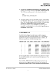
2.5 M4500/P4500/D4591 INSTALLATION
The following is provided only as a reference. These steps are performed by the factory prior to
shipping the HSL-CUP3. These steps need only be performed in the event either the M4500
module, P4500 power supply, or D4591 display need to be replaced. Refer to the M4500 User's
Manual for general details on installing the M4500, P4500, and D4591.
________________________________________________________________________________
2.5.1 M4500 MODULE INSTALLATION
To install the M4500 module, perform the following:
1) Remove the cover from the M4500 chassis (retained with three captive screws on the lower
front of the cover and two captive screws on each side of the M4500 chassis).
2) Install S4573 (SLOT0-0): Set the slot address dip switches (SW1) on the S4573 to the following
positions (slot0):
S4573:
SW1 switch1 = "OFF"
SW1 switch2 = "OFF"
Install the S4573 in Slot0-0 (furthest left slot) of the M4500 chassis.
3) Install S4568 (SLOT0-1): Set the slot address dip switches (SW1) on the S4568 to the following
positions (slot1):
S4568:
SW1 switch1 = "ON"
SW1 switch2 = "OFF"
Install the S4568 in Slot0-1 (slot next to S4573) of the M4500 chassis.
HSL-CUP3 User’s Manual
SYSTEMS Electronics Group
- 14 -
SECTION 2
INSTALLATION
4) Install S4516 (SLOT0-3) (OPTIONAL): Set the slot address dip switches (SW2) on the S4516
to the following positions (slot3):
S4516:
SW2 switch1 = "ON"
SW2 switch2 = "ON"
Set the RS-232/RS-422 select dip switches (SW1) on the S4516 to the following positions (RS232 selected):
S4516:
SW1 switch1 = "ON"
SW1 switch2 = "OFF"
Install the S4516 in Slot0-3 of the M4500 chassis.
5) Install the cover back over the M4500, making sure all the board connectors protrude through
the slots in the cover. Tighten the three captive screws on the lower front of the cover and the
two captive screws on each side of the M4500 chassis.
6) Connect the display ribbon cable to the connector on the back of the M4500 (the connector on
the cable is polarized and should mate with the connector on the M4500 only one way).
7) Mount the M4500 chassis to the HSL-CUP3 back panel using four 8-32 screws.
8) With power to the P4500 "off", install the P4500 power supply cable to the +5/C/+12/C/-12
connector on the M4500 (the connector on the cable is polarized and should mate with the
connector on the M4500 only one way).
9) Install the respective field wiring arms on all the I/O boards of the M4500 (I/O slots0 and 1,
MODBUS connector on USER PORT, resolver connector, and IN0/IN1 connector). Make sure
all the field wiring connectors are fully mated in the M4500.
HSL-CUP3 User’s Manual
SYSTEMS Electronics Group
- 15 -
SECTION 2
INSTALLATION
________________________________________________________________________________
2.5.2 P4500 POWER SUPPLY INSTALLATION
To install the P4500, perform the following steps:
1) Mount the P4500 to the HSL-CUP3 in the mounting holes next to the M4500 (left side) using
two 8-32 screws.
2) With power to the P4500 "off", install the P4500 power supply cable to the +5/C/+12/C/-12
connector on the M4500 (the connector on the cable is polarized and should mate with the
connector on the M4500 only one way).
________________________________________________________________________________
2.5.3 D4591 KEYPAD/DISPLAY INSTALLATION
To install the D4591, perform the following steps:
1) With the gasket installed on the mounting studs of the D4591, install the D4591 in the cut-out
either in the HSL-CUP3 enclosure or the cut-out in the user's existing control cabinet. Secure
the display to the enclosure using 7ea. 8-32 nuts and external lock washers.
2) Connect the display ribbon cable to the connector on the lower back of the display (the
connector on the cable is polarized and should mate with connector on the M4500 only one
way).
HSL-CUP3 User’s Manual
SYSTEMS Electronics Group
- 16 -
SECTION 2
INSTALLATION
________________________________________________________________________________
2.5.4 DOWNLOAD HSLCUP3 PROGRAM AND SET-UP DATA TO M4500
Once the M4500/P4500/D4591 are installed, perform the following to download the HSLCUP3
application program to the M4500 as well as download the previously saved set-up data and timing
channel set-points:
1) Power up the M4500 and the IBM PC or compatible used to interface with the HSL-CUP3.
2) Connect an RS-232 cable from the computer COM port to the "PROG" port on the M4500.
3) From the computer's menu program, select the respective cupper's "SET-UP CUPPER"
selection (this was set in section 2.3.1). The "HSLCUP3" set-up program will be invoked with
the corresponding HSLCUP3 application program for that cupper.
4) Download the HSLCUP3 application program to the M4500 by selecting "4: Download
Program to M4500" from the HSL-CUP3 main menu. A prompt will be displayed verifying the
download, press the <ENTER> key to start the download. Once the download is complete, press
any key to return to the HSL-CUP3 main menu. See section 3.4 for complete details.
5) Download the PLS timing set-points to the M4500 by selecting "2: Machine Timing" from the
HSL-CUP3 main menu. From the PLS main development menu, select "4: Download Channels
to PLS". Press the <ENTER> key to start the download. Press any key to return back to the PLS
main development menu. Press 12<ENTER> to return back the HSL-CUP3 main menu.
6) Download the previously saved to disk set-up data to the M4500 by selecting "5: Download Setup data to M4500" from the HSL-CUP3 main menu. Press the <ENTER> key to start the
download. Once the download is complete, press any key to return to the HSL-CUP3 main
menu. See section 3.5 for complete details.
7) The M4500 is now ready to run, loaded with the HSLCUP3 application program, timing setpoints, and set-up data that was previously saved for the respective cupper. Press <ESC> to
return back to the computer's menu software program.
HSL-CUP3 User’s Manual
SYSTEMS Electronics Group
- 17 -
SECTION 2
INSTALLATION
(This Page Intentionally Left Blank)
HSL-CUP3 User’s Manual
SYSTEMS Electronics Group
- 18 -
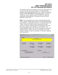
SECTION 3
USING THE “HSLCUP3”
SET-UP PROGRAM
The "HSLCUP3" set-up program is a DOS based menu driven program which allows the user to
easily view the HSL-CUP3 data or alter the HSL-CUP3 set-up variables using an IBM PC or
compatible. In addition to setting the set-up variables, "HSLCUP3" can be used to set the machine
timing (machine offset, timing signal locations, etc.). The set-up variables are used to configure and
tune the HSL-CUP3 to match the configuration and performance of the specific cupper (see section
2.4).
The main menu of the "HSLCUP3" set-up program incorporates the following menu selections:
1:
2:
3:
4:
5:
6:
Set Cupper/Lubricator Set-up Parameters
Set Machine Timing
Shift Data/Brake Response
Download Program to M4500
Download Set-up data to M4500
Upload (Save) Set-up data from M4500
Note: The "HSLCUP3" program is an on-line communications program used to interface with the
M4500 module. The data displayed in the menus and set in the menus is communicated directly to
the M4500. Therefore, prior to selecting any of the above selections, make sure an RS-232 cable is
connected from the COM port on the computer running "HSLCUP3" to the "PROG" port on the
M4500.
The following sections are a complete description of the "HSLCUP3" selections and menus.
________________________________________________________________________________
3.1 SET CUPPER/LUBRICATOR SET-UP PARAMETERS
The Cupper/Lubricator set-up menu is used to set the various set-up parameters in the M4500. This
menu is invoked by selecting "1: Set Cupper/Lubricator Set-Up Parameters" from the Main Menu.
Note: Prior to selecting this selection, make sure the RS-232 cable is connected from the COM port
on the computer to the PROG PORT on the M4500.
HSL-CUP3 User’s Manual
SYSTEMS Electronics Group
- 19 -
SECTION 3
USING THE “HSLCUP3”
SET-UP PROGRAM
________________________________________________________________________________
3.1.1 CUPPER/LUBRICATOR PARAMETER DEFINITIONS
Brake Wear Compensation Enable? (0=No, 1=Yes): This prompt is used to enable or
disable the brake wear compensation. If the compensation is to be disabled, enter "0" and press
<ENTER>. If the compensation is to be enabled, enter "1" and press <ENTER>.
Desired TDC Stop Position (Low Speed): This is the desired stopping location (in degrees)
for a TDC stop in low speed when the brake wear compensation is enabled. This is typical set to
000 degrees (Top Dead Center)..
Desired TDC Stop Position (High Speed): This is the desired stopping location (in degrees)
for a TDC stop in high speed when the brake wear compensation is enabled. This is typical set to
000 degrees (Top Dead Center).
Maximum Allowed Stopping Response (degrees): This defines what the maximum allowed
brake response is before the "Brake Response Too Long" alarm is generated. If the actual brake
response (number of degrees from when the brake is activated to the position where the press ends
up at rest) when a TDC stop is performed is longer than this number, the alarm is generated. If the
actual brake response is less, the alarm is not generated. Set this parameter to the value where the
brake response is considered too long and service to the brake should be performed (typically 270
to 300 degrees).
Running Cupper Low Speed (SPM): This is the speed (in strokes per minute) that the cupper
will run when in low speed.
Running Cupper High Speed (SPM): This is the speed (in strokes per minute) that the cupper
will run when in high speed.
Lubricator Maximum Speed (CPM): The "Lubricator Maximum Speed" parameter is used to
scale the 0-10VDC analog output such that when the cupper is running at the speed entered in
"Lubricator Maximum Speed", the analog output will be at 10 volts. This is typically set to the
running high speed of the Cupper or slightly higher.
Lubricator Idle Speed (CPM): This parameter determines the speed the lubricator will run at
when the cupper is stopped (de-clutched).
Note: When the cupper is running, the lubricator speed reference is proportional (as set by the
"Lubricator Maximum Speed" scaling) to the speed of the cupper. This parameter is used to provide
the speed reference when the cupper speed is zero.
HSL-CUP3 User’s Manual
SYSTEMS Electronics Group
- 20 -
SECTION 3
USING THE “HSLCUP3”
SET-UP PROGRAM
________________________________________________________________________________
3.1.2 CUPPER/LUBRICATOR SET-UP PARAMETER SELECTIONS
The menu selections on the "Cupper/Lubricator Set-Up Parameters" menu allow you to set the setup variables listed under the following menu selections:
1: Enable/Disable Brake Wear Compensation
- Enable/Disable Brake wear compensation
- Desired TDC Stop Position (Low speed)
- Desired TDC Stop Position (High speed)
2: Maximum Allowed Cupper Stopping Response
- Maximum Allowed Cupper Stopping Response
3: Set Cupper Running Speeds
- Low Speed (SPM)
- High Speed (SPM)
4: Set Lubricator Speed References
- Maximum Speed (CPM)
- Idle Speed (CPM)
To set a particular variable, select the corresponding menu selection and follow the prompts as they
occur.
________________________________________________________________________________
3.2 SET MACHINE TIMING
The Set Machine Timing selection is used to invoke the PLS programming command menus (these
are the same menus used in SYSdev to program the PLS section of the M4500). When selected, the
PLS programming main development menu will be invoked using the default CUP3TMG channel
set-point file. From this menu, the user can zero the machine (set the resolver offset) and adjust the
timing signal set-points. The following sections describe how to perform these functions, section 5
provides a complete description of each timing signal.
Note: Prior to selecting the Machine Timing selection, make sure the RS-232 cable is connected
from the COM port on the computer to the PROG PORT on the M4500.
HSL-CUP3 User’s Manual
SYSTEMS Electronics Group
- 21 -
SECTION 3
USING THE “HSLCUP3”
SET-UP PROGRAM
________________________________________________________________________________
3.2.1 ZEROING THE MACHINE
To set the machine zero (resolver offset) perform the following:
1) Connect the RS-232 cable from the COM port on the computer to the "PROG" port on the
M4500.
2) Select the "2: Set Machine Timing" selection from the HSL-CUP3 set-up program main menu.
3) Select "1: Online Channel Setpoint Programming" from the Main Development menu.
4) Select "F9: POS/RPM" and observe the "POS:" field. Verify that as the machine is rotated
forward (either inching or barred) that the position increases linearly from 0 through 359. If not,
swap the S1 and S3 leads of the resolver at the M4500 resolver connector. Then verify that the
position then indeed does increase with forward movement. Press "ESC" to exit the
"POS/RPM" update.
5) Position the machine at top dead center.
6) Auto zero the resolver by selecting "F10: Set Offset". Enter "0" in the offset field and press
<ENTER>.
7) The M4500 will calculate the actual offset value required to make this the 000 position and will
display this number in the offset field. The position will now read 0.
8) Exit back to the PLS Main Development menu by pressing <ESC>. Exit back to the
"HSLCUP3" set-up main menu by pressing <ESC> again.
HSL-CUP3 User’s Manual
SYSTEMS Electronics Group
- 22 -
SECTION 3
USING THE “HSLCUP3”
SET-UP PROGRAM
________________________________________________________________________________
3.2.2 ADJUSTING THE TIMING CHANNEL SET-POINTS
To set or alter any of the timing signal set-points, perform the following:
1) Connect the RS-232 cable from the COM port on the computer to the "PROG" port on the
M4500.
2) Select the "2: Set Machine Timing" selection from the HSL-CUP3 set-up program main menu.
3) Select "1: Online Channel Setpoint Programming" from the Main Development menu.
4) Set all channels per section 5. Set-points are entered for a particular channel simply by typing in
the set-point in the form XXX-YYY<ENTER> in the first set-point of the given channel.
Note: Up to 50 set-points may be entered for any channel. However for the cupper only one
set-point is used per channel and this should be entered in the number 1 set-point.
The XXX is the location the set-point will turn "on" while YYY is the location where the setpoint will turn "off". Use the PgUp, PgDn, F1:Next Chan, or F2: Prev Chan keys to select the
desired channel for programming.
5) Once all channels are programmed, press <ESC> to exit back to the PLS Main Development
Menu. Press <ESC> again to exit back to the "HSLCUP3" set-up main menu. The new channels
will be saved both in the M4500 and in the "CUP3TMG" file on the hard drive.
HSL-CUP3 User’s Manual
SYSTEMS Electronics Group
- 23 -
SECTION 3
USING THE “HSLCUP3”
SET-UP PROGRAM
________________________________________________________________________________
3.3 SHIFT DATA
The shift data menu displays the following information:
Current Shift:
Total Strokes
Last Shift:
Total Strokes
Brake Response:
Low Speed
High Speed
This data is the totals so far into the current shift and the totals for the last (previous) shift. The
current shift data is transferred to the "Last shift" data when the end of shift bit (set via the RS-232
data communications) transfers from a "0" to a "1". This can be at the end of either an 8 or 12 hour
shift. This data cannot be reset either from this menu or by the operator, only at the end of shift
transition.
In addition to the shift data, this screen also shows the brake response of the brake for both high and
low speeds. This data is updated after each TDC stop.
To exit back to the main menu, press <ESC>.
________________________________________________________________________________
3.3.1 SHIFT DATA DEFINITIONS
Total Strokes: This is the total number of strokes the press has made for the shift. This is essentially
a can counter.
Low Speed Brake Response (degrees): This is the number of degrees from the when the
clutch was de-activated (at the TDC (Lo) timing) to where the cupper crankshaft came to rest when
a TDC stop was performed at Low speed. This can be used to determine the general condition of the
brake and whether servicing of the brake is required.
High Speed Brake Response (degrees): This is the number of degrees from the when the
clutch was de-activated (at the TDC (hi) timing) to where the cupper crankshaft came to rest when a
TDC stop was performed at high speed. This can be used to determine the general condition of the
brake and whether servicing of the brake is required.
HSL-CUP3 User’s Manual
SYSTEMS Electronics Group
- 24 -
SECTION 3
USING THE “HSLCUP3”
SET-UP PROGRAM
________________________________________________________________________________
3.4 DOWNLOAD PROGRAM TO M4500
This selection is used to download the HSLCUP3 application program to the M4500 module. This
should only be performed when either replacing the M4500 module (see section 2.5) or when the
program has been changed. To download the program, perform the following:
Note: Program download cannot be performed while the cupper is running. All outputs on the
M4500 are turned "off" and no program execution is performed. The clutch would therefore be
disengaged. The cupper should be stopped before the download takes place (approximately 15 to 45
seconds depending on the computer used).
1) Connect the RS-232 cable from the COM port on the computer to the "PROG" port on the
M4500.
2) Select "4: Download Program to M4500". A prompt will be displayed asking to continue or
abort. To continue, press any key except the <ESC> key. To abort, press the <ESC> key. If a
prompt stating that the "HSLCUP3.REV" file could not be opened is displayed, then the
"HSLCUP3" application program is not installed in the current directory. To install the
program, perform the steps in section 2.3.3 to install the program.
3) Once program download is initiated, M4500 program execution will cease, the current address
being downloaded will be displayed, and the "RUN" LED on the M4500 will flash
continuously.
4) Once the download is complete, the "RUN" LED on the M4500 will illuminate solid and
program execution in the M4500 will resume. Press any key to return back to the "HSLCUP3"
main menu.
HSL-CUP3 User’s Manual
SYSTEMS Electronics Group
- 25 -
SECTION 3
USING THE “HSLCUP3”
SET-UP PROGRAM
________________________________________________________________________________
3.5 DOWNLOAD SET-UP DATA TO M4500
This selection is used to download the previously uploaded (saved) set-up variables to the M4500.
This should only be performed when replacing the M4500 module (see section 2.5).
Note: The set-up data consists of the cupper and lubricator set-up parameters (see section 3.1).
Timing channel set-points are not stored as part of the set-up data. To download the set-up data,
perform the following:
1) Connect the RS-232 cable from the COM port on the computer to the "PROG" port on the
M4500.
2) Select "5: Download Set-up data to M4500". A prompt will be displayed asking to continue or
abort. To continue, press any key except the <ESC> key. To abort, press the <ESC> key.
3) Once data download is initiated, the current address being downloaded will be displayed.
Note: M4500 program execution is not ceased, therefore data download can be performed
while the machine is running.
4) Once set-up data download is complete, press any key to return to the "HSLCUP3" main menu.
HSL-CUP3 User’s Manual
SYSTEMS Electronics Group
- 26 -
SECTION 3
USING THE “HSLCUP3”
SET-UP PROGRAM
________________________________________________________________________________
3.6 UPLOAD (SAVE) SET-UP DATA FROM M4500
This selection is used to save the set-up variables from the M4500 to the hard drive (current
directory selected). This should be performed anytime any of the set-up variables have been
changed.
Note: When the set-up variables are changed, they are changed directly in the M4500, not on the
file in the computer. By uploading (saving) the set-up variables to disk, they can be downloaded to
the M4500 in the event the module must be replaced. The set-up data consists of the cupper and
lubricator set-up parameters (see section 3.1). Timing channel set-points are not stored as part of the
set-up data. To upload the set-up data, perform the following:
1) Connect the RS-232 cable from the COM port on the computer to the "PROG" port on the
M4500.
2) Select "6: Upload (Save) Set-up data from M4500". A prompt will be displayed asking to
continue or abort. To continue, press any key except the <ESC> key. To abort, press the <ESC>
key.
3) Once data upload is initiated, the current address being uploaded will be displayed.
Note: M4500 program execution is not ceased, therefore data upload can be performed while
the machine is running.
4) Once set-up data upload is complete, press any key to return to the "HSLCUP3" main menu.
HSL-CUP3 User’s Manual
SYSTEMS Electronics Group
- 27 -
SECTION 3
USING THE “HSLCUP3”
SET-UP PROGRAM
(This Page Intentionally Left Blank)
HSL-CUP3 User’s Manual
SYSTEMS Electronics Group
- 28 -
SECTION 4
USING THE HSL-CUP3
KEYPAD/DISPLAY
The keypad of the HSL-CUP3 contains 24 keys consisting of data display commands, set-up
commands, and a numeric keypad. The display of the HSL-CUP3 is 2 line by 40 character back-lit
LCD display which displays the selected data and set-up menus. The keypad/display can be used by
the operator to view data or can be used to adjust the timing and all set-up parameters.
The display/keypad allows the following to be viewed or adjusted:
1)
2)
3)
4)
5)
6)
7)
Set the Cupper Set-Up Parameters
Set the Lubricator Speed References
Set Machine Timing
Set Machine Zero
View the Actual Brake Response (in degrees)
View the Current Shift Data
View the Last Shift Data
The definitions of the keypad commands and menus are described in the following sections.
Note: For virtually all the menus, the "NEXT" and "PREV" keys can be used to advance to the
next item of the menu or retard to the previous item on the menu.
________________________________________________________________________________
4.1 DEFAULT SCREEN
The default screen (displayed when no other commands are active) contains the following data:
MACHINE SPEED (SPM):xxxx POSITION:xxx
TOTAL STROKES:xxxxxxx
Where the "Machine Speed" is the current speed of the cupper, the "Position" is the current angular
position of the cupper crankshaft, and the "Total Strokes" field is the total number of strokes the
press has made so far into the current shift. This display effectively replaces a speed meter, a
position display, and a counter. This screen is always returned to when no commands are active.
________________________________________________________________________________
4.2 "BRAKE RESPONSE" KEY
This key displays the brake response of both low speed and high speed stops. The response is the
number of degrees it takes the press to stop from when the clutch is de-activated for a TDC stop to
the position that the machine comes to rest. This can be used to determine the general condition of
the brake and whether servicing of the brake is required. To exit back to the default screen, simply
press the "ESC" key.
HSL-CUP3 User’s Manual
SYSTEMS Electronics Group
- 29 -
SECTION 4
USING THE HSL-CUP3
KEYPAD/DISPLAY
________________________________________________________________________________
4.3 "LAST SHIFT" KEY
The Last shift data menu displays the following information:
TOTAL STROKES:
This data is the totals for the last (previous) shift. This data is transferred from the current shift to
the "Last shift" data when the end of shift bit (set via the RS-232 communications) transfers from a
"0" to a "1". This can be at the end of either an 8 or 12 hour shift. This data cannot be reset by the
operator, only at the end of shift transition.
Note: The Current shift "Total Strokes" is displayed as part of the default screen (see section 4.1).
________________________________________________________________________________
4.3.1 LAST SHIFT DATA DEFINITIONS
Total Strokes: This is the total number of strokes the press made for the previous shift. This is
essentially a counter.
________________________________________________________________________________
4.4 "SET-UP" KEY
This selection is used to invoke the primary set-up menu. This consists of the following four
selections:
1:
2:
3:
4:
SET CUPPER PARAMETERS
SET LUBRICATOR SPEED REFERENCE
SET MACHINE TIMING (SET-POINTS, ETC.)
ZERO MACHINE (SET RESOLVER OFFSET)
When selected, each of the above selections bring up a sub-menu with the corresponding set-up
parameters. The following sections describe these sub-menus and the definitions of the
corresponding variables. To select the respective set-up sub-menu, simply press the corresponding
numeric key (1 thru 4).
HSL-CUP3 User’s Manual
SYSTEMS Electronics Group
- 30 -
SECTION 4
USING THE HSL-CUP3
KEYPAD/DISPLAY
________________________________________________________________________________
4.4.1 SET CUPPER PARAMETER
This menu is activated when the "1" key (SET CUPPER PARAMETERS) is pressed while the
primary set-up menu is active. The following four set-up parameters may then be adjusted or
viewed:
BRAKE WEAR COMP ENBLE? (0=NO, 1=YES): This prompt is used to enable or disable the
brake wear compensation. If the compensation is to be disabled, enter "0" and press <ENTER>. If
the compensation is to be enabled, enter "1" and press <ENTER>.
DESIRED TDC STOP POS (LOW SPEED): This is the desired stopping location (in degrees)
for a TDC stop in low speed when the brake wear compensation is enabled. This is typical set to
000 degrees (Top Dead Center). This prompt is only displayed when the brake wear compensation
is enabled.
DESIRED TDC STOP POS (HIGH SPEED): This is the desired stopping location (in degrees)
for a TDC stop in high speed when the brake wear compensation is enabled. This is typical set to
000 degrees (Top Dead Center). This prompt is only displayed when the brake wear compensation
is enabled.
MAXIMUM ALLOWED STOPPING RESPONSE: This defines what the maximum allowed
brake response is before the "Brake Response Too Long" alarm is generated. If the actual brake
response (number of degrees from when the brake is activated to the position where the press ends
up at rest) when a TDC stop is performed is longer than this number, the alarm is generated. If the
actual brake response is less, the alarm is not generated. Set this parameter to the value where the
brake response is considered too long and service to the brake should be performed (typically 270
to 300 degrees).
RUNNING CUPPER LOW SPEED (SPM): This is the speed (in strokes per minute) that the
cupper will run when in low speed.
RUNNING CUPPER HIGH SPEED (SPM): This is the speed (in strokes per minute) that the
cupper will run when in high speed.
The "NEXT" and "PREV" keys can be used to advance to the next parameter or the previous
parameter respectively. To change the currently displayed parameter, simply enter the new value on
the numeric keypad and press <ENTER>. The value will be entered and the next parameter will
automatically be displayed. When the last parameter (Running Cupper High Speed) is entered, the
primary set-up menu is again displayed. Pressing <ESC> at anytime will also exit you back to the
primary set-up menu.
HSL-CUP3 User’s Manual
SYSTEMS Electronics Group
- 31 -
SECTION 4
USING THE HSL-CUP3
KEYPAD/DISPLAY
________________________________________________________________________________
4.4.2 SET LUBRICATOR SPEED REFERENCE
This menu is activated when the "2" key (SET LUBRICATOR SPEED REFERENCE) is pressed
while the primary set-up menu is active. The following lubricator set-up parameters may then be
adjusted or viewed:
LUBRICATOR MAXIMUM SPEED (CPM): The "Lubricator Maximum Speed" parameter is
used to scale the 0-10VDC analog output such that when the cupper is running at the speed entered
in "Lubricator Maximum Speed", the analog output will be at 10 volts. This is typically set to the
running high speed of the Cupper or slightly higher.
LUBRICATOR MINIMUM SPEED (CPM): This parameter determines the speed the lubricator
will run at when the cupper is stopped (de-clutched).
Note: When the cupper is running, the lubricator speed reference is proportional (as set by the
"Lubricator Maximum Speed" scaling) to the speed of the cupper. This parameter is used to provide
the speed reference when the cupper speed is zero.
The "NEXT" and "PREV" keys can be used to advance to the next parameter or the previous
parameter respectively. To change the currently displayed parameter, simply enter the new value on
the numeric keypad and press <ENTER>. The value will be entered and the next parameter will
automatically be displayed. When the last parameter (Lubricator Minimum Speed) is entered, the
primary set-up menu is again displayed. Pressing <ESC> at anytime will also exit you back to the
primary set-up menu.
HSL-CUP3 User’s Manual
SYSTEMS Electronics Group
- 32 -
SECTION 4
USING THE HSL-CUP3
KEYPAD/DISPLAY
________________________________________________________________________________
4.4.3 SET MACHINE TIMING (SET-POINTS, ETC.)
This selection brings up the timing set-point menu which displays the following fields:
CHuu SETPOINT:xxx [] "channel name"
RPM:yyyy POS:zzz OFFSET:wwww SCALE:360
Each field is defined as follows:
Field
Chuu
Definition
Currently selected channel (CH00 thru CH17) where "uu" is the octal channel
number.
SETPOINT:xxx
Channel "on" or "off" set-point where "xxx" is the set-point position
[]
State of channel set-point (blank = "off", solid block character = "on")
"channel name"
selected channel name: (CH00) TDC (HIGH) TIMING, (CH01) TDC (LOW)
TIMING, etc.
RPM:yyyy
Current machine speed where "yyyy" is in CPM.
POS:zzz
Current resolver position where "zzz" is in degrees.
OFFSET:wwww
Resolver offset where "wwww" is the offset in degrees.
SCALE:360
Resolver SCALE FACTOR (360 degrees per revolution).
In addition to displaying the timing set-point menu, the following keys are also enabled: "ENTER
SET-POINT", "CLEAR CHANNEL", "SELECT CHANNEL", and "SEARCH CHANNEL".
The "ENTER SET-POINT" key is used to enter a new set-point (both "on" and "off" set-points) in
the selected channel. The "CLEAR CHANNEL" key is used to clear all set-points from the selected
channel. The "SELECT CHANNEL" key is used to select a new channel for programming. The
"SEARCH CHANNEL" is used to view both the "on" and "off" set-points in the selected channel.
Searching Channel: To view the set-points in a channel simply press the "SEARCH
CHANNEL" key. The next "off" to "on" or "on" to "off" position is shown in the "SETPOINT"
field. If the transition was "off" to "on", the state character [] will be a solid block. If the transition
was "on" to "off", the state character [] will be blank.
HSL-CUP3 User’s Manual
SYSTEMS Electronics Group
- 33 -
SECTION 4
USING THE HSL-CUP3
KEYPAD/DISPLAY
Entering or Adjusting Set-point: To set or adjust a timing channel, perform the following:
1) Select the channel to be adjusted by pressing the "SELECT CHANNEL" key, entering the
channel number (00 to 17) and pressing enter. In addition, the "NEXT" and "PREV" keys can
be used to advance to the next channel or retard to the previous channel.
2) Press "CLEAR CHANNEL" to clear the existing set-point out.
Note: Entering a new set-point does not automatically clear the old set-point out. If the two setpoints are not in the same place, the channel will simply have two set-points in it if the old one
is not cleared out first. Therefore always clear the channel before entering a new set-point. A
set-point may, however, be "extended" by programming another set-point onto an existing setpoint using either the existing "on" or "off" set-point as the starting position for the new setpoint. This will result in one larger set-point.
3) Press "ENTER SET-POINT" to enter the new set-point. The display will then prompt ""ON"
SETPOINT:". Enter the position (in degrees) where the set-point should go "on" and press
<ENTER>. The display will now prompt ""OFF" SETPOINT:". Enter the position (in degrees)
where the set-point should go "off" and press <ENTER>. The channel will now be programmed
with a set-point that goes "on" at the "on" position entered and "off" at the "off" position
entered.
4) Exit back to the primary set-up menu by pressing <ESC>. Exit back to the default screen by
pressing <ESC> again.
HSL-CUP3 User’s Manual
SYSTEMS Electronics Group
- 34 -
SECTION 4
USING THE HSL-CUP3
KEYPAD/DISPLAY
________________________________________________________________________________
4.4.4 ZERO MACHINE (SET RESOLVER OFFSET)
This selection is used to auto zero the resolver. To set the machine zero (resolver offset) perform
the following:
1) Select "3: SET MACHINE TIMING" and observe the "POS:" field. Verify that as the machine
is rotated forward (either inched or barred) that the position increases linearly from 0 through
359. If not, swap the S1 and S3 leads of the resolver at the M4500 resolver connector. Then
verify that the position then indeed does increase with forward movement. Press "ESC" to exit
back to the primary set-up menu.
2) Position the machine at machine zero (top dead center).
3) Auto zero the resolver by selecting "4: ZERO MACHINE" from the primary set-up menu. Enter
"0" to zero the resolver. The timing set-up menu will be displayed, now showing the "POS:" at
zero.
4) The M4500 will calculate the actual offset value required to make this the 000 position and will
display this number in the offset field.
5) Exit back to the primary set-up menu by pressing <ESC>. Exit back to the default screen by
pressing <ESC> again.
HSL-CUP3 User’s Manual
SYSTEMS Electronics Group
- 35 -
SECTION 4
USING THE HSL-CUP3
KEYPAD/DISPLAY
(This Page Intentionally Left Blank)
HSL-CUP3 User’s Manual
SYSTEMS Electronics Group
- 36 -
SECTION 5
GENERAL TIMING SIGNAL LOCATIONS
The following is a general description of the timing signals and the locations they should be set at:
CH00: TDC (HIGH) TIMING: This signal is used to de-activate the clutch for a TDC stop at high
speed.
Note: The leading edge is used to de-activate the clutch, thus the width of the signal is not
critical (generally set 20 degrees wide). When the brake wear compensation is enabled,
this signal is adjusted automatically by the M4500. If the brake wear compensation is
disabled, this signal must be set manually. In this case is should be set such that the press
stops at top dead center for a TDC stop at high speed.
CH01: TDC (LOW) TIMING: Same as the TDC (High) timing (CH00) except used when the
machine is running in low speed.
CH02: DIE JAM CHECK TIMING: This signal is used by the host PLC to perform the Die
Jam Check. This should be set per the algorithm the host PLC uses to perform the check.
CH03: CUP JAM CHECK TIMING: This signal is used by the host PLC to perform the Cup
Jam Check. This should be set per the algorithm the host PLC uses to perform the check.
CH04: DIE CHECK RESET TIMING: This signal is used by the host PLC as part of the Die
Jam/Cup Jam die protection. This should be set per the algorithm the host PLC uses to
perform the check.
CH05: AIR STRIP TIMING: This signal is used to activate the air strip solenoid. The air strip is
"on" for the entire window that CH05 is "on" while the machine is running. This signal is
generally set "on" about 120 degrees and then set "off" at about 200.
CH06: SCRAP JAM TIMING: This signal is used by the host PLC to perform the Scrap Jam
Check. This should be set per the algorithm the host PLC uses to perform the check.
CH07: STROKE COUNT TIMING: This signal is used by the host PLC to count strokes.
CH10: MOTION TIMING: This signal is provided to the PLC via a discrete DC output. This is
used by the host PLC to detect when the crankshaft is moving as a back-up to verify that
the clutch was activated when commanded to. This is a pulse train set "on" for 30 degrees
and then set "off" for 30 degrees through-out the entire channel.
HSL-CUP3 User’s Manual
SYSTEMS Electronics Group
- 37 -
SECTION 5
GENERAL TIMING SIGNAL LOCATIONS
(This Page Intentionally Left Blank)
HSL-CUP3 User’s Manual
SYSTEMS Electronics Group
- 38 -
SECTION 6
RECOMMENDED SPARE PARTS
The following are recommended spares for the HSL-CUP3. These parts are available through
Systems Engineering Assoc. Inc.
Quantity
Part Number
1ea.
1ea.
1ea.
1ea.
1ea.
M4500
P4500
S4568
S4573
D4591
Description
PLC/PLS Processor/Chassis – 4 Slot
Power Supply
8 input/8 output 10-30VDC I/O Board
16 point 10-30VDC Output Board
Display/Keypad
HSL-CUP3 User’s Manual
SYSTEMS Electronics Group
- 39 -
SECTION 6
RECOMMENDED SPARE PARTS
(This Page Intentionally Left Blank)
HSL-CUP3 User’s Manual
SYSTEMS Electronics Group
- 40 -
APPENDIX A
MODBUS COMMUNICATIONS
The MODBUS communications driver uses the S4516 communications board to both read and
write data to a MODICON PLC.
The following data is written to the MODICON PLC:
MODICON Dest
4x Address
401700
401701
401702
401703
401704
401705
401706
401707
401708
401709
401710
401711
Data Definition
Speed (CPM)
Resolver Position
Number of Strokes (Lo-0 to 9,999)
Number of Strokes (Hi-10,000's)
Spare Count
Status (to MODICON)
Hi Speed Brake Response (degrees)
Lo Speed Brake Response (degrees)
TDC Timing "On" (Hi) - BW Comp
TDC Timing "Off" (Hi) - BW Comp
TDC Timing "On" (Lo) - BW Comp
TDC Timing "Off" (Lo) - BW Comp
M4500 Source
Address
W182
W180
W1100
W1102
W1104
W790
W1042
W1040
W2120
W2122
W2124
W2126
The definitions of the data sent from the M4500 to the MODICON are as follows:
401700:
Speed - Current strokes per minute of the cupper
401701:
Resolver Position - Current angular position of the cupper crankshaft (in degrees)
401702:
Number of Strokes - This is the total number of strokes the press has made so far in
the current shift. This is essentially a counter.
401704:
Spare Count - Not Used.
401706:
Hi Speed Brake Response (degrees) - This is the number of degrees from the when
the clutch was de-activated (at the TDC (hi) timing) to where the cupper crankshaft
came to rest when a TDC stop was performed at high speed. This can be used to
determine the general condition of the brake and whether servicing of the brake is
required.
401707:
Lo Speed Brake Response (degrees) - This is the number of degrees from the when
the clutch was de-activated (at the TDC (Lo) timing) to where the cupper crankshaft
came to rest when a TDC stop was performed at Low speed. This can be used to
determine the general condition of the brake and whether servicing of the brake is
required.
HSL-CUP3 User’s Manual
SYSTEMS Electronics Group
- A-1 -
APPENDIX A
MODBUS COMMUNICATIONS
401708:
TDC Timing "On" (Hi) [BW Comp] - This is the "on" set-point of the TDC (Hi)
timing (CH00) when modified by the brake wear compensation algorithm. This is
modified by the M4500 when the brake wear compensation is enabled and CH00
was reprogrammed when the brake response was too long or too short on a high
speed TDC stop. This is only updated if the brake wear compensation is enabled,
otherwise it is not used.
401709:
TDC Timing "Off" (Hi) [BW Comp] - This is the "off" set-point of the TDC (Hi)
timing (CH00) when modified by the brake wear compensation algorithm. This is
modified by the M4500 when the brake wear compensation is enabled and CH00
was reprogrammed when the brake response was too long or too short on a high
speed TDC stop. This is only updated if the brake wear compensation is enabled,
otherwise it is not used.
401710:
TDC Timing "On" (Lo) [BW Comp] - This is the "on" set-point of the TDC (Lo)
timing (CH01) when modified by the brake wear compensation algorithm. This is
modified by the M4500 when the brake wear compensation is enabled and CH01
was reprogrammed when the brake response was too long or too short on a low
speed TDC stop. This is only updated if the brake wear compensation is enabled,
otherwise it is not used.
401711:
TDC Timing "Off" (Lo) [BW Comp] - This is the "off" set-point of the TDC (Lo)
timing (CH01) when modified by the brake wear compensation algorithm. This is
modified by the M4500 when the brake wear compensation is enabled and CH01
was reprogrammed when the brake response was too long or too short on a low
speed TDC stop. This is only updated if the brake wear compensation is enabled,
otherwise it is not used.
The bits of the Status register (to the MODICON from the M4500) are mapped as follows:
W790: Status to MODICON (4x address 401705 in MODICON)
B790.0: Not Used
B790.1: Not Used
B790.2: Timing Signal Fail Alarm
B790.3: Brake Wear Alarm
B790.4: Not Used
thru
B791.7: Not Used
HSL-CUP3 User’s Manual
SYSTEMS Electronics Group
- A-2 -
APPENDIX A
MODBUS COMMUNICATIONS
The Status bits sent to the MODICON PLC are defined as follows:
B790.2:
Timing Signal Fail Alarm - The timing signal fail occurs when any of the timing
signals generated in the PLS section fail to change state periodically while the
machine is running.
B790.3:
Brake Response Too Long - The "Brake Response Too Long" alarm is generated
when the actual brake response exceeds a user specified maximum allowed brake
response. This can be used to indicate that service to the brake should be performed.
The following data is read from the MODICON PLC:
MODICON Dest
4x Address
401760
401761
401762
401763
401764
401765
401766
401767
401768
401769
401770
401771
401772
401773
401774
401775
401776
401777
401778
401779
401780
401781
401782
401783
Data Definition
Status/Control (from MODICON)
CH00 "On" - TDC Timing (Hi)
CH00 "Off" - TDC Timing (Hi)
CH01 "On" - TDC Timing (Lo)
CH01 "Off" - TDC Timing (Lo)
CH02 "On" - Die Jam Check Timing
CH02 "Off" - Die Jam Check Timing
CH03 "On" - Cup Jam Check Timing
CH03 "Off" - Cup Jam Check Timing
CH04 "On" - Die Check Reset Timing
CH04 "Off" - Die Check Reset Timing
CH05 "On" - Air Strip Timing
CH05 "Off" - Air Strip Timing
CH06 "On" - Scrap Jam Timing
CH06 "Off" - Scrap Jam Timing
CH07 "On" - Stroke Count Timing
CH07 "Off" - Stroke Count Timing
BW Comp Desired Stop (Lo)
BW Comp Desired Stop (Hi)
Max Allowed Stop Response (BW Alarm)
Cupper Running Low Speed
Cupper Running High Speed
Lubricator Maximum Speed (Calibrate)
Lubricator Idle Speed
HSL-CUP3 User’s Manual
M4500 Source
Address
W900
W902
W904
W906
W908
W910
W912
W914
W916
W918
W920
W922
W924
W926
W928
W930
W932
W934
W936
W938
W940
W942
W944
W946
SYSTEMS Electronics Group
- A-3 -
APPENDIX A
MODBUS COMMUNICATIONS
The definitions of the data read from the MODICON to the M4500 are as follows:
401761:
thru
401776:
CH00 "On" - TDC Timing (Hi)
401777:
BW Comp Desired Stop (Lo) - This is the desired stopping location (in degrees) for
a TDC stop in low speed when the brake wear compensation is enabled. This is
typical set to 000 degrees (Top Dead Center)..
401778:
BW Comp Desired Stop (Hi) - This is the desired stopping location (in degrees) for a
TDC stop in high speed when the brake wear compensation is enabled. This is
typical set to 000 degrees (Top Dead Center).
401779:
Max Allowed Stop Response (BW Alarm) - This defines what the maximum allowed
brake response is before the "Brake Response Too Long" alarm is generated. If the
actual brake response (number of degrees from when the brake is activated to the
position where the press ends up at rest) when a TDC stop is performed is longer
than this number, the alarm is generated. If the actual brake response is less, the
alarm is not generated. Set this parameter to the value where the brake response is
considered too long and service to the brake should be performed (typically 270 to
300 degrees).
401780:
Cupper Running Low Speed - This is the speed (in strokes per minute) that the
cupper will run when in low speed.
401781:
Cupper Running High Speed - This is the speed (in strokes per minute) that the
cupper will run when in high speed.
CH07 "Off" - Spare Timing
Variables 401761 thru 401776 are the "On" and "Off" timing set-points for CH00
thru CH07 respectively. This allows the MODICON to program these timing
channels when the "Timing Channel Program Enable" bit (401760.3 from the
MODICON) is set to a "1". These are the same "On" and "Off" set-points that would
normally be set through the HSL-CUP3 keypad (see section 4.4.3 of the HSL_WI3
User's manuals) or set through the HSLCUP3 set-up program (See section 3.2.2 of
the HSL-CUP3 User's manual). See section 5 of the HSL-CUP3 user's manual for the
definitions of the CH00 through CH07 timing channels.
HSL-CUP3 User’s Manual
SYSTEMS Electronics Group
- A-4 -
APPENDIX A
MODBUS COMMUNICATIONS
401782:
Lubricator Maximum Speed (Calibrate) - The "Lubricator Maximum Speed"
parameter is used to scale the 0-10VDC analog output such that when the cupper is
running at the speed entered in "Lubricator Maximum Speed", the analog output will
be at 10 volts. This is typically set to the running high speed of the Cupper or
slightly higher.
401783:
Lubricator Idle Speed - This parameter determines the speed the lubricator will run
at when the cupper is stopped (de-clutched).
Note: When the cupper is running, the lubricator speed reference is proportional (as
set by the "Lubricator Maximum Speed" scaling) to the speed of the cupper. This
parameter is used to provide the speed reference when the cupper speed is zero.
Note: The above parameters (401777 thru 401773) are effective only when the "Set-Up Parameters
Enable" bit (401760.2 from the MODICON) is set to a "1". Otherwise these variables are not
updated in the M4500.
The bits of the Status/Control register (from the MODICON to M4500) are mapped as follows:
W900: Status/Control from MODICON (4x address 401760 in MODICON)
B900.0: End of Shift
B900.1: Brake Wear Compensation Enable
B900.2: Set-Up Parameters Enable
B900.3: Timing Channel Program Enable
B900.4: Set Resolver Zero (Auto-Zero)
B900.5: Alarm Reset
B900.6: Not Used
thru
B901.7: Not Used
HSL-CUP3 User’s Manual
SYSTEMS Electronics Group
- A-5 -
APPENDIX A
MODBUS COMMUNICATIONS
The Status/Control bits sent from the MODICON PLC are defined as follows:
B900.0:
End of Shift - Setting this bit to a "1" transfers the current shift data in the M4500 to
the last shift data and clears the current shift data (to start data collection for the next
shift). The current shift data in the MODICON should be saved to the last shift data
stack prior to setting this bit.
B900.1:
Brake Wear Compensation Enable - This bit is used to enable or disable the brake
wear compensation. If the compensation is to be disabled, set B900.1 to a "0". If the
compensation is to be enabled, set B900.1 to a "1".
B900.2:
Set-Up Parameters Enable - Setting this bit to a "1" enables the set-up parameters
(401777 thru 401783 in the MODICON) to be used in the M4500. If this bit is set to
a "0", the values in 401777 thru 401783 in the MODICON are not used as the set-up
parameters, the M4500 instead uses the values set-up thru the HSL-CUP3 keypad or
the "HSLCUP3" set-up program.
B900.3:
Timing Channel Program Enable - Setting this bit to a "1" enables the CH00 thru
CH07 "On" and "Off" set-points (401761 thru 401776) from the MODICON to be
used as the set-points for CH00 thru CH07 in the PLS section of the M4500. If this
bit is set to a "0", the values in 401761 thru 401776 in the MODICON are not used
as the set-points, the M4500 instead uses the values set-up thru the HSL-CUP3
keypad or the "HSLCUP3" set-up program.
B900.4:
Set Resolver Zero (Auto Zero) - Setting this bit sets the PLS offset such that the
current position is "0". To set the resolver zero, position the machine at Top Dead
Center and then set this bit to a "1". The resolver position will now read 000. Reset
this bit back to "0" when done.
B900.5:
Alarm Reset - Setting this bit to a "1" resets the timing signal fail alarm and the
brake response too long alarm.
HSL-CUP3 User’s Manual
SYSTEMS Electronics Group
- A-6 -
APPENDIX A
MODBUS COMMUNICATIONS
The MODBUS driver uses the following data format and parameters (the MODBUS port on the
MODICON PLC must be set to match these):
MODBUS Port (PLC address):
MODBUS Baud:
MODBUS framing mode:
Number of start bits:
Number of data bits:
Number of stop bits:
Parity:
5
19.2K
RTU
1
8
1
NONE
HSL-CUP3 User’s Manual
SYSTEMS Electronics Group
- A-7 -