1
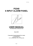
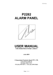
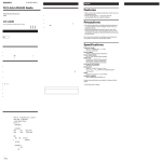
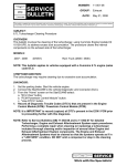
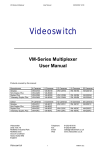
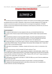
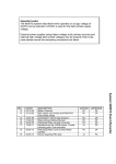
23227-01
P2263
ALARM PANEL
USER MANUAL
FOR OPERATING SYSTEM 23223-01
August 2009
© Associated Controls (Australia) Pty. Limited
2-4 Norfolk Road,
Greenacre NSW 2190.
PH (02) 9642 4922, FAX (02) 9642 4955
Page 1 of 17
23227-01
Table of Contents
1.
2.
3.
4.
Introduction
P2263 Introduction
3
Unit Description
FRONT PANEL - Main Electronics
1)
40 Digit Display
2)
5 LED’s
3)
Switches
4)
7 Segment Display
RS232 Socket
Network Socket
Network Termination Link
Network Select/Deselect Link
Alarm Relay
Connector PCB
Inputs
4
4
4
4
5
5
6
8
8
8
8
9
Unit Operation
Use Of Unit
Mute Button
Test Button
Display Audio Level
Unit Set Up - Installer Accessible Only
Error Messages
Normal Operation
Set Up Mode
12
12
12
12
12
14
14
15
Specifications
Specifications
Socket Connections
16
17
Page 2 of 17
23227-01
1
Introduction
P2263 INTRODUCTION
The P2263 is a direct replacement for the P2262. They are functionally
identical with the P2263 having an improved display.
The P2263 Alarm Panel is designed to monitor up to 24 local inputs
and up to 150 networked inputs. Both audible and visual indication of
any alarm condition is provided. Networked input information is
obtained from other panels connected to the network.
Each local or networked input can be programmed to have a unique
message assigned to it which will be displayed when the input is in the
alarm condition. In addition to the message, one of two LED’s can be
selected to provide a steady or flashing status. If the non-alarm
condition is satisfied on all inputs used, a common “system
normal” message is displayed along with the green LED. If more than
one alarm condition exists simultaneously, the appropriate messages
are displayed in sequence; however the highest priority LED (Red) will
always be displayed should one of the messages require it. This warns
the operator that an emergency message is contained in the rotating
sequence even if the current message being displayed is of a low
priority. A single digit seven segment display is also provided to display
how many messages are in the queue, if there are more than 9
messages, the number nine will continue to be displayed and will flash.
The audible alarm is sounded with each new alarm condition detected.
It can be muted using the mute switch, however it will sound again
after a predefined time should the alarm condition still exist.
Local input connection to the P2263 is made via plug in terminal
blocks. The terminal blocks are mounted on a separate dedicated PCB
that can be suitably mounted at the installation wiring stage. This
allows the main electronics to be kept safely out of harms way until
final commissioning of the system, at which point, the main electronics
is plugged into the connector PCB via a ribbon cable.
Network connection is made directly to the main electronics via an 8
way plug.
If networking is not required, it can be disabled by removing a plug in
link on the main PCB, the unit then functions as a “local” 24 input stand
alone alarm panel.
All P2263 programming is done via a 4 pin RS232 plug and socket that
couples it to a computer. This feature permits full custom set up of
Messages, LED’s, Input Type, Audio Repeat Period etc.
Page 3 of 17
23227-01
2
Unit Description
FRONT PANEL - Main Electronics
The main electronics PCB is mounted to a metal backing plate.
The front panel presents the operator with the following items.
A 40 digit 5 x 7 dot matrix vacuum fluorescent display.
Five LED’s, 2 x Red, 2 x Amber, 1 x Green.
Three switches, Test, Mute & Audio Level Check.
A single digit 7 Seg display.
1)
40 Digit Display - used to convey all messages to the operator.
2)
5 LED’s - There are 3 LED’s, Red, Amber & Green associated
with input alarm conditions. These LED’s provide an operator
with a quick visual status of the panel. If the green LED is on, all
is considered normal; this LED is associated with the “System
Normal” message only & does not flash. The Red and Amber
LED’s are associated with alarm messages, providing a simple
method of prioritorising an alarm as a warning (amber) or
emergency (red), both Red and Amber LED’s can be on solid or
flashed when illuminated, this depends on what was selected
when the panel was being programmed.
Two additional LED’s provide information on the panel itself. A
Red LED is provided to indicate an electronics failure and will
illuminate solid (non flashing) when such a state exists. An
Amber LED is provided as a secondary warning indicator for
messages relating to the panel itself, e.g. input S/C or O/C
problems, network problems etc.
3)
Switches - There are three switches, Test, Mute & Display audio
level.
Mute is used to silence the audible alarm once an operator has
been made aware of the alarm condition. The mute button is
also used to put the panel into “off” mode. (see operation
section).
Test switch initiates a test cycle that sounds the audible alarm,
cycles each LED on & off, then cycles through all the
messages programmed, both local and networked, with their
associated LED’s, the test routine is then terminated. The test
cycle can be terminated at any time by operating the Test
switch a second time. The test program is automatically
terminated if an alarm condition is detected while in test mode.
Display audio level sounds the audio and uses the display as a
bar graph to display the level setting. The level display will auto
Page 4 of 17
23227-01
cancel after 3 sec, or it can be manually cancelled be operating
the display audio level button a second time.
4)
Single digit 7 Seg display - This display indicates how many
alarm messages are in the queue to be displayed. If the number
is greater than 9, the number 9 will be displayed and flashed.
RS232 SERIAL PORT SOCKET
The RS232 connection is made via a 4 way socket on the left side of
the unit, (see fig 5 below). When connected to a computer running
“APM” software supplied by Associated Controls, the operator can
configure the P2263 as required.
The RS232 socket also serves as the output socket for connection to a
BMS should it be required. The P2263 has to be configured at setup to
perform as a BMS interface.
Each panel outputs it’s alarm status onto the network whenever there
is a change to any of it’s input conditions, i.e. any input changes from
alarm to non-alarm or non-alarm to alarm, or every 20 sec as a system
heart beat. This information is received by the P2263 being used as
the BMS interface and redirected to the RS232 port.
This alarm information is in the following format:AA
NN
NN
NN
AA
Unique panel ID number assigned at set up. It is transmitted as
2 ASCII characters, e.g. panel #1 would be sent as $30, $31
(01). Panel #10 would be sent as $30, $41 (0A). Panel #250
would be sent as $46, $41 (FA).
NN
Three 8 bit bytes representing the alarm status for 24 inputs,
0 = non alarm, 1= alarm. Each byte is transmitted as 2 ASCII
characters. Input bit assignment is as follows:1st byte (7 6 5 4 3 2 1 0) =
inputs 1 to 8
bit 7 =
input 1
bit 6 =
input 2
bit 5 =
input 3
bit 4 =
input 4
bit 3 =
input 5
bit 2 =
input 6
bit 1 =
input 7
bit 0 =
input 8
2nd byte (7 6 5 4 3 2 1 0)
bit 7
bit 6
bit 5
bit 4
Page 5 of 17
=
=
=
=
=
inputs 9 to 16
input 9
input 10
input 11
input 12
23227-01
bit 3
bit 2
bit 1
bit 0
3 rd byte (7 6 5 4 3 2 1 0)
bit 7
bit 6
bit 5
bit 4
bit 3
bit 2
bit 1
bit 0
=
=
=
=
input 13
input 14
input 15
input 16
=
=
=
=
=
=
=
=
=
inputs 17 to 24
input 17
input 18
input 19
input 20
input 21
input 22
input 23
input 24
Each status byte is again sent as 2 ASCII characters, eg. if input 1 was
in alarm, the first status byte would be (80) and thus sent as $38, $30.
If inputs 1 and 2 were in alarm the byte would be (C0), thus sent as
$43, $30.
The panel ID and each of the status bytes are separated by spaces
and preceded with a line feed and carriage return. Therefore a typical
string for a panel would be as follows, eg. panel #11 in the non alarm
state..
$0A $0D $30 $42 $20 $30 $30 $20 $30 $30 $20 $30 $30
The information is presented in this format so that it can be received
and displayed by a computer running a simple terminal program as a
means of checking the system output.
IMPORTANT!
The output from the panels is RS232, it has limitations on the distance
that it can be transmitted (approx 10 metres). If a greater distance is
required a different version of the terminal block PCB can be used
which has an RS422 interface incorporated.
NETWORK SOCKET
The network connection is made via either one of two 8 way sockets
on the left hand of the unit, (see Fig 5 below). Two sockets are
provided, should a “daisy chain” wiring configuration be required. The
system wiring can be of any configuration as shown if Fig 1 to 4 below,
however there are limits on the cable length. The maximum total wire
length in the installation is 450 metres and the maximum distance
between any nodes (to any node) or termination is 250 metres.
Page 6 of 17
23227-01
The cable length figures above apply to a category 5 UTP solid twisted
pair cable. Only 2 of the 8 ways of the network socket are used at this
stage (see specifications for pin outs). 8way is provided for future
expansion.
Figure 1 Loop Topology
Figure 2 Mixed Topology
Figure 3 Single Terminated Bus Topology
Page 7 of 17
23227-01
Figure 4 Star Topology
NETWORK TERMINATION LINKS
While the network system used by the P2263 is of a “Free Topology”
nature, it still requires one termination on the network. It is not critical
where the termination should be, so long as it is there. Each panel has
the ability to provide the termination, only one on the network is
required. There are 2 link blocks beside the 8 way network sockets to
the left of the unit, they are marked as “TERM.” and “S/D”. To provide
termination both links should be installed, both should be left out if
termination is not required.
NETWORK SELECT/DESELECT LINK
A network select link is provided on the left hand side of the main
board labelled as “NET SEL”. If this link is left out the P2263 functions
as a “stand alone” 24 local input alarm panel. All network functions are
ignored, therefore no network error messages will be displayed.
If this link is installed, the P2263 functions as a fully networked panel
and expects to communicate with other panels as set up at installation.
If communication is lost with these panels, error messages will be
displayed to that effect.
ALARM STATUS RELAY
There is an alarm status relay provided, this relay is wired as a fail safe
device, being normally energised in the non alarm state & deenergised in the alarm state, thus providing an alarm signal should
supply to the panel fail, or in the event of an alarm during normal
operation. Connection to the relay contacts is via a terminal block on
the “Connector PCB”.
CONNECTOR PCB
All connections to the P2263, with the exception of the network, are
made via the separate terminal block PCB. There are 3 banks of 12
way T/B’s, with 8 inputs & 4 commons per bank, totalling 24 inputs and
Page 8 of 17
23227-01
12 commons. There is a 6 way block as well, providing for connection
of supply and a clean set of changeover contacts from the alarm status
relay. Three 8 way DIP switches provide source resistor isolation for
the 24 inputs ( see “inputs” ).
INPUTS
The 24 inputs can be configured to accept a switch input directly or to
monitor the input line for alarm, non-alarm, open circuit or short circuit
conditions. All 24 inputs must be configured as switched or monitored,
they can’t be mixed. Each input has an internal 1K pullup resistor to
supply current from an internally regulated 7.5V supply, to the external
switch or line monitoring circuit.
In switched mode an input voltage less than 3.6V is considered to be
in the non-alarm condition. Above 3.6V is considered as an alarm
condition.
Monitored inputs rely on a balanced string of resistor values to operate
correctly. This resistive string is distributed between the monitor PCB
mounted in the pressure switch housing and the alarm panel input
itself. Each input provided a current sourcing resistor to drive the
monitor PCB, if more than one P2263 input in connected to a monitor
PCB, action must be taken to remove all but one of these sourcing
resistors otherwise the balance is lost and incorrect voltage levels will
result.
The P2263 accommodates this with 3 x 8 way dip switches on the
connector PCB. If a switch is ON the sourcing resistor is in circuit, if a
switch is OFF the resistor is removed.
In monitored mode an input voltage below 1.65V is a short circuit,
between 1.65V - 3.68V is the non-alarm condition, between 3.68V 5.8V is the alarm condition, above 5.8V is an open circuit. The
following summary shows the relationship between the input voltage
and the corresponding analogue value expressed in both decimal and
hexadecimal. The alarm and non-alarm figures shown show a
monitored line with zero resistance (470R & 1470R) and one with a
total of 150 ohms (620R & 1620R).
Page 9 of 17
23227-01
SUMMARY
MONITORED MODE
x..................... x............... x.......... x.......
|
S/C
|
NON-ALARM
0
56
|
0
$38
|
|
0V
1.65V
|
|
|
|
|
|
MON. BRD READINGS
81
97
$51
$61
2.4V
2.9V
470R 620R
x....... x....... x....... x......................
|
ALARM
|
O/C
123 |
|
194
$7B |
|
$C2
3.68V |
|
5.8V
|
|
|
|
150
$96
4.46V
1470R
|
156
$9C
4.64V
1620R
SWITCHED MODE
x......................................................…… x...........................................................
|
NON-ALARM
|
ALARM
0
122
0
$7A
0V
3.6V
Page 10 of 17
x
|
244
$F4
7.5V
x
|
244
$F4
7.5V
23227-01
4 way
SOCKET POSITION DETAIL
4 way
8 way 8 way
DISPLAY
8 way
8 way
4 way
8 way
Figure 5
Page 11 of 17
23227-01
3
Unit Operation
USE OF UNIT
From the user point of view there is very little to know. An
understanding of the messages and the priority rating of the LED’s is
essential, This is a “local”, or “site” issue and can’t be explained here.
Otherwise, there are only three pushbuttons that can be operated on
the front panel, “Test”, “Mute” & “Display Audio Level”.
Mute The Mute pushbutton is used to silence the audible alarm once
an alarm has been raised. If the alarm condition is forgotten,
and left unattended, the audible alarm will sound again after a
predefined period as a reminder, again it can be silenced with
the Mute button. This cycle will continue until the alarm
condition is removed. The predefined period is selected and set
at installation.
If the mute button is held down for 3 sec. the panel will go into a
shutdown mode and display the message “UNIT OFF” . If held
down in the “off” mode for 3 sec, the panel will turn back on
again. This feature is useful to prevent false alarms during
installation of a network system.
Test The Test button initiates a test cycle that sounds the audible
alarm, cycles each LED on & off, then cycles through all the
resident messages programmed, both local and networked, with
their associated LED’s, the test routine is then terminated. The
test cycle can be terminated at any time by operating the test
button a second time. The test program is automatically
terminated if an alarm condition is detected while in test mode.
Display Audio Level The display audio level button allows the operator
to view and hear the current audio level that is programmed.
Operation of this button will sound the audio and convert the
display to a horizontal bar graph that displays the set level. The
audio level can be set at 1 of 8 levels when the unit is
programmed at installation. For each unit of level the display will
show 4 solid blocks, therefore level 1 will show 4 blocks, level 2
will show 8 blocks, and so on up to 32 blocks for level 8. This
display mode will self cancel after 3 sec, or can be manually
cancelled by operation of the “display” button a second time.
UNIT SET UP - Installer Accessible Only
With the exception of those hardware features already described, the
P2263 is configured at installation using “APM” (Alarm Panel
Management) software supplied by Associated Controls. The “APM”
Page 12 of 17
23227-01
software is run on a suitable computer connected to the P2263 panel
via the RS232 socket.
The “APM” software has its own User Manual giving detailed
instruction on its use. A summary only of the features will be given
here.
The “APM” software has two sections.
1)
File Generation Mode
File generation is the first step in setting up a P2263 panel. It contains
all the messages, both local and networked, with associated LED
information. It also contains a unique panel ID number, identification
message, audio level, audio repeat time & local input mode (switched
or monitored) The computer need not be connected to the P2263 at
this stage.
This file can be downloaded to a P2263 panel using the second
section “monitor mode”. No further panel setup is required if the file
information is correct.
2)
Monitor Mode
The Monitor Mode is used to communicate with the P2263; the
computer must be connected to the P2263 panel when using this
section.
When the communications cable is connected to the P2263 panel the
message “SETUP MODE” will be displayed when the panel is ready to
proceed.
The functions provided in monitor mode are as follows:Download
Used to send a file generated under “File Generation” to the
P2263 panel.
Upload
Used to receive a file from a P2263 panel. This is useful if a
panel setup has been modified and a file record is required, it
can be uploaded from the panel; therefore, it is not necessary
to generate a new file under “File Generator”
Display Setup
Will display the current panel setup information
Unit ID
Unit Message ID
Number Of Local Messages Programmed.
Number Of Remote Messages Programmed
Current Audio Level
Current Audio Repeat time
Current Input Mode
Page 13 of 17
23227-01
Display Messages
Will display all the programmed messages, both local and
networked.
Display inputs
Will display in real time the current analogue value present at
each of the 24 inputs. This command is a very useful tool during
system commissioning. Input values are in hexadecimal.
e.g.
NO. 01 02 03 04 05 06 07 08 09 10 11 12 13 14 15 16 17 18 19 20 21 22 23 24
I/P 55 56 56 56 56 56 55 56 56 DE E0 E1 DC DC E4 DB E5 DE D8 DC DB E4 55 55
Audio Level
This function allows direct adjustment of the alarm audio level.
Audio Repeat Time
This function allows direct adjustment of the alarm audio repeat
timer.
Input Mode
Used to directly select the local input operating mode i.e.
switched or monitored.
ERROR MESSAGES
The P2263 has numerous error messages that will be displayed.
These messages are divided into two categories, those that will be
displayed during normal operation and those that will be displayed
during set up. What they are and their meaning is given below.
Normal Operation Error Messages
Displayed on the P2263 Display.
SHORT CIRCUIT I/P = (I/P No)
When the inputs are configured as monitored inputs, this message will
be displayed if a short circuit is detected on an input.
OPEN CIRCUIT I/P = (I/P No)
When the inputs are configured as monitored inputs, this message will
be displayed if an open circuit is detected on an input.
NO MESSAGE THIS I/P = (I/P No)
This message will be displayed in either switched or monitored modes
if the signal level on an input is such that it indicates an input device is
connected and no associated message is programmed.
Page 14 of 17
23227-01
EEPROM FAIL, REPLACE PROC.
This message can be displayed at any time. It will occur if an
unsuccessful attempt in made to write to the EEPROM. It if a serious
problem and the P2263 should be returned for service.
NO INPUTS PROGRAMMED
If the P2263 is turned on with no inputs programmed this message will
appear.
NETWORK COMMUNICATION FAILURE
If total network failure is experienced this message will appear.
COMMUNICATION FAILURE WITH UNIT (panel ID number )
If network communication with a specific panel is experienced this
message will appear followed by the lost panel ID number.
Set Up Mode Error Messages
Displayed on the P2263 Display.
ERROR - CHECK SUM MISMATCH
or
ERROR - BYTE COUNT MISMATCH
or
FILE TRANSMISSION NOT ACK
These messages will appear on the P2263 display if an error is
encountered during the uploading or downloading of message files.
Page 15 of 17
23227-01
4
Specifications
SPECIFICATIONS
Power Consumption
Operating Voltage - 12 Volts AC +/- 10%
Current Consumption - 0.7 Amps
Power Consumption - 8 Watts
Environmental Conditions
Operating Temperature Range - 0 - 45 Deg C
Operating Humidity Range - 95% R.H. non-condensing
Inputs
All input devices should be of a passive nature. No externally
generated voltages should be applied.
Maximum current supplied by an input circuit is = 7.5 ma.
Maximum loop resistance of input cable = 150 ohms
Relay Output
Alarm status relay contact rating = 1A @ 30V DC
Serial Output Format
1200 Baud, 8 Bit, 1 Stop, No Parity
Network Information
Cable Type - Category 5 UTP solid
Cable Length
Maximum total length in system
= 450 metres
Maximum length any node to any node or termination = 250 metres
Network Frequency - 78 kbps
Maximum Number Of Nodes - 30
Page 16 of 17
23227-01
Socket Connections
Pin numbering runs left to right
Figure 6
Figure 6 numbering applies to both 4 way RS232 socket and 8 way
Network sockets
RS232 4 Way
Pin No.
1
2
3
4
Function
Common ( Ground )
N/C
TXD ( Data Out )
RXD ( Data In )
Network 8 Way
Pin No.
1
2
3
4
5
6
7
8
Function
N/C
N/C
N/C
N/C
N/C
N/C
Network
Network
Page 17 of 17