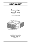
1
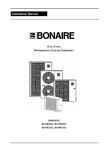
Installation Manual
DUCTED REVERSE CYCLE
REFRIGERATED AIR CONDITIONING
B007RS, B009RS, B012RS, B015RS, B016RT, B019RT
DUCTED REVERSE CYCLE REFRIGERATED AIR CONDITIONING
Table of Contents
General ......................................................................................................................................... 4
UNIT DETAILS ................................................................................................................................. 5
Outdoor Unit Dimensions .............................................................................................................. 5
Outdoor Unit Access and Clearances ........................................................................................... 7
Indoor Unit Dimensions ................................................................................................................. 8
Indoor Unit Clearances ................................................................................................................. 9
UNIT INSTALLATION .................................................................................................................... 10
Indoor Installation........................................................................................................................ 10
Indoor Unit Location ................................................................................................................................ 11
Floor or Platform Mounting...................................................................................................................... 12
Suspension Mounting.............................................................................................................................. 12
Leveling the Unit...................................................................................................................................... 12
Outdoor Unit ................................................................................................................................ 13
Condenser Installation ................................................................................................................ 14
Interconnecting Tubing................................................................................................................ 14
Installation Notes..................................................................................................................................... 15
Unit Interconnecting Tubing Table .......................................................................................................... 15
Recommendation for Interconnection Tubing Installation....................................................................... 16
Pipe Installation........................................................................................................................... 17
Flare Preparation..................................................................................................................................... 17
Pipe Welding Preparation........................................................................................................................ 17
Pipe Welding ........................................................................................................................................... 18
Connecting the tubes .............................................................................................................................. 18
Evacuation and setting in operation ............................................................................................ 19
Additional Charge........................................................................................................................ 20
Drain Line Installation.................................................................................................................. 20
ELECTRICAL CONNECTIONS...................................................................................................... 21
Indoor Unit Connections.............................................................................................................. 21
Outdoor Unit Connections ........................................................................................................... 22
Wiring Diagram - Single Phase Indoor Unit................................................................................. 22
Wiring Diagram - Single Phase Outdoor Unit.............................................................................. 23
Wiring Diagram - 3 Phase Outdoor Unit...................................................................................... 24
CONTROL INSTALLATION........................................................................................................... 25
Before Starting ............................................................................................................................ 25
Installation ............................................................................................................................................... 25
Setting Up the Thermostat ...................................................................................................................... 26
Coding The Unit ...................................................................................................................................... 26
COMMISSION ................................................................................................................................ 27
Operating Parameters ................................................................................................................. 27
Setting the Operating Parameters............................................................................................... 27
Led Operation And Interpretation ................................................................................................ 28
Commissioning Check List .......................................................................................................... 29
Page 3
DUCTED REVERSE CYCLE REFRIGERATED AIR CONDITIONING
General
GENERAL
Bonaire Ducted Reverse Cycle air conditioners include two separate units – Indoor and Outdoor
Unit. The two units are interconnected by two refrigerant tubes and an electric cable. Unit
functions are controlled by a Radio Frequency Remote controller or a hard wired low voltage
controller (depending on the option purchased).
WARNING
The air conditioner must be installed by authorized technicians, according to Climate Technologies
specifications and using recommended standard tubing, electric cables and proper installation
tools. Failure to comply with the above may invalidate your warranty!
Page 4
DUCTED REVERSE CYCLE REFRIGERATED AIR CONDITIONING
Dimensions & Clearances
Unit Details
OUTDOOR UNIT DIMENSIONS
B007RS
B009RS
B012RS
Unit
Weight
A
B
C
B007RS
60kg
870
860
340
B009RS
92kg
970
960
365
160
90
B012RS
97kg
970
960
365
160
90
Page 5
D
E
Connections Inside Unit
DUCTED REVERSE CYCLE REFRIGERATED AIR CONDITIONING
Dimensions & Clearances
B015RS
B016RT
B019RT
Unit
Weight
A
B
C
B015RS
103kg
970
1260
395
Connections Inside Unit
B016RT
108kg
970
1260
395
Connections Inside Unit
B019RT
131kg
970
1460
365
Page 6
D
160
E
90
DUCTED REVERSE CYCLE REFRIGERATED AIR CONDITIONING
Dimensions & Clearances
OUTDOOR UNIT ACCESS AND CLEARANCES
When the back is close to the Wall
In selecting a proper location, the following criteria
must be considered:
The top and the front need to be open.
This includes protruding window sills.
a)
b)
The outdoor unit and the indoor unit must be
installed as close to each other as possible, within
10m. If longer tubing is required see table on
page 14 or consult your technical sales rep.
Outdoor unit installation should provide for:
1. Easy service access.
2. Minimum disturbance to the owner and nearby
neighbors.
3. A minimum distance of 100 mm from the wall
4. If installed in a closed place (balcony, attic, etc),
outdoor air vent must be provided to prevent
hot/cold air from recirculation through the
outdoor unit.
5. If several outdoor units are installed in the
same area, make sure that the hot air outlet
from one outdoor unit does not enter another
outdoor unit.
6. Verify that any wall on which the outdoor unit is
installed is capable of carrying the unit’s
weight. Do not install on a light unstable
structure susceptible to vibration.
7. When installing on a balcony above the first
floor, make sure that the outdoor unit location
allows easy access for removal of the top
cover and/or the entire unit, if necessary.
8. If the outdoor unit is installed in a nonaccessible location, long and flexible
refrigerant tubing and electrical cable must be
installed to allow the unit to be moved for
servicing.
9. Do not install the unit in a highly polluted area
in which the air is contaminated by oil mist, salt
or sulfuric gas.
Multiple Units – Lateral and Behind relationships
When the top is blocked
The front and the sides must be clear for
these minimum clearances.
When the back & sides are blocked
The back and the side minimum
clearances must be achieved
When all the sides are blocked
If all sides are blocked, this will be an
unacceptable installation
Page 7
DUCTED REVERSE CYCLE REFRIGERATED AIR CONDITIONING
Dimensions & Clearances
INDOOR UNIT DIMENSIONS
Unit Dimensions
Unit
Net
Weight
A
B
C
D
E
F
G
H
I
B007HD
39Kg
946
891
246
510
716
831
381
292
251
B009HD
39Kg
946
891
246
510
716
831
381
292
251
B012HD
46Kg
1181
1126
721
510
951
1066
401
342
281
B015HD
46Kg
1181
1126
721
510
951
1066
401
342
281
B016HD
49Kg
1301
1246
721
510
1071
1186
401
342
295
B019HD
53Kg
1301
1246
721
510
1071
1186
401
342
295
Page 8
DUCTED REVERSE CYCLE REFRIGERATED AIR CONDITIONING
Dimensions & Clearances
INDOOR UNIT CLEARANCES
Clearance Options for Maintenance
Unit
(Mandatory)
Fan Removal Clearances Options
A
A+B
C
D
B007HD
500
500
500
450
B009HD
500
500
500
450
B012HD
500
850
850
450
B015HD
500
850
850
450
B016HD
500
850
850
450
B019HD
500
850
850
450
Page 9
DUCTED REVERSE CYCLE REFRIGERATED AIR CONDITIONING
Unit Installation
Unit installation
INDOOR INSTALLATION
Page 10
DUCTED REVERSE CYCLE REFRIGERATED AIR CONDITIONING
Unit Installation
Indoor Unit Location
The indoor unit is designed for installation
within a ceiling/roof space or other
compartment, where there is no influence
from outdoor conditions.
While selecting the location, the following
conditions must be assured:
a) The location should assure free flow of the
return air into the unit without interference.
b) The unit should not be installed close to
rooms where noise should be avoided
(bedrooms, children rooms, etc).
1.
Insulated Acoustic ducting
2.
Discharge air grilles
c) Consider air distribution from the unit to
the rooms and select a suitable location
for even air flow.
3.
Transition duct – air off
4.
Suspended hanging option –
indoor fan coil
d) Avoid obstacles which may restrict the run
air intake or the discharge supply air flow.
5.
Indoor Fan Coil
6.
Platform Option – Indoor fan coil
e) If installing the unit on a platform ensure
that the structure is capable of supporting
the indoor unit and platform.
7.
Transition duct – air on
8.
Return air grille
NOTE: The indoor unit should not be installed
outside.
9. Electrical Box
Notes for Installation
a) The return-air duct should be as short as possible, with full acoustic lining inside. The cross
section at the duct connection to the unit shall be equal to that of the unit.
b) The distance between the return air grille and the air intake on the unit must be as short as
possible.
Design and prepare in advance easy access for servicing as follows:
c) The minimum height clearance for the installation is 410 mm.
d) Allow the access to the electrical control box to facilitate its easy removal by opening the cover
(fastened by 4 screws).
e) A distance of 500 mm must be kept to allow access to the electrical service panel. For the
maintenance of fan and motor see indoor unit clearances. See Page 7.
Page 11
DUCTED REVERSE CYCLE REFRIGERATED AIR CONDITIONING
Unit Installation
Floor or Platform Mounting
1. Create a platform using bearers and
chipboard. Place the unit platform over load
bearing walls or on strategically located
trusses in the roof space.
2. Place serrated rubber pads or isolating
springs under each corner of the unit to
minimize / eliminate any noise transmission.
Suspension Mounting
Use the accessory kit – P/n 6601905 Hanging
Bracket Kit. For installation detailed see the
instructions supplied with this accessory kit.
1. Fasten the hanging brackets to the indoor coil.
2. Use field supplied threaded rod to suspend the
unit.
M10 or greater is recommended to brace the unit
mounting.
3. Fix the threaded rod to a structurally sound part of
the roof or concrete pad.
Check with local and national building codes and
or a structural engineer as to the fixing of the unit
or building support structure if applicable.
4. Secure the indoor fan unit to the threaded rods
ensuring all fasteners are secure and tight.
Failure to correctly secure the suspension
brackets and threaded rod to the indoor unit
could cause it to fall and inflict injury or damage.
Leveling the Unit
1. Adjust the level of the unit as required. The
drainpipe end of the unit must be lower by at
least 5mm for good drainage.
2. Take care not to damage the drain tubes or
coil when lifting to adjust unit level
3. For suspension mounting units, tighten the
locking nuts once the revised position is
determined.
Page 12
DUCTED REVERSE CYCLE REFRIGERATED AIR CONDITIONING
Unit Installation
OUTDOOR UNIT
Page 13
DUCTED REVERSE CYCLE REFRIGERATED AIR CONDITIONING
Unit Installation
CONDENSER INSTALLATION
Installation on flat surface (roof, ground, etc)
Install outdoor unit support in a position elevated at
least 100 mm on a concrete pad, concrete block or
wooden beams, in order to allow free water flow
underneath.
1. Outside the building
2. Outdoor Unit
3. Floor
4. Concrete slab or equivalent
5. Wall
6. Anchor bolts
7. Serrated Rubber / Waffle Pad 40x80 mm
INTERCONNECTING TUBING
The tubing between the indoor and outdoor units consist of two copper tubes and an electric cable
routed through a 60-mm wall opening. In addition, a drainage hose is installed between the indoor
unit and the closest drainage point. Connect both sections, taking the shortest, most direct route.
1. Outside wall
2. Gas (Vapor) Line
3. Liquid Line
4. Electric Cable
5. Inside wall
6. Incline Angle
Page 14
DUCTED REVERSE CYCLE REFRIGERATED AIR CONDITIONING
Unit Installation
Installation Notes
1. When laying the tubing for the installation, make sure that
the ends are sealed to prevent penetration of dirt, moisture
etc. To prevent dust or moisture from entering the tubes,
seal them with caps or masking tape. It is recommended
to clean the inside space of the tubes with nitrogen before
connecting them to the unit.
2. Whenever possible, avoid passing tubes through hot
zones, such as walls next to ovens, chimneys, etc. In
such cases, additional insulation or other means of
protection should be employed.
3. Tubing route shall be kept in straight lines as much as
possible. When installing, keep the number of tube bends
to a minimum. If bends are necessary, perform them only
by using professional tube benders and not manually.
4. Make sure that tubing is insulated on its entire length,
including tube end and quick connectors, or flare-nuts, to
avoid tube “sweating” and water dripping from it.
5. Tubing shall be of refrigerant grade, without any damage.
Tube inside walls must be kept absolutely clean prior to
and during installation operations.
6. The Gas line shall be individually insulated with a minimum
9mm (3/8”) thick closed cell pipe insulation.
7. For diameters, length of liquid and gas lines, and height
difference, see the table below for each model. If the
liquid or gas tube diameters differs from the corresponding
flare connector diameter (mounted on the unit), use a
suitable reducing union for this purpose.
NOTE: it is not a requirement to insulate the liquid line unless
it is exposed to direct sun or extreme ambient temperatures.
Unit Interconnecting Tubing Table
UNIT
MODEL
CONNECTING
LINE
TUBING LENGTH, UP TO – (IN METRES, ONE WAY)
10
15
20
25
MAXIMUM
HEIGHT
DIFFERENCE
20M
10M
B007RS
Gas
Liquid
15.88mm (⅝”)
9.58mm (⅜”)
15.88mm (⅝”)
9.58mm (⅜”)
19.05MM (¾”)
9.58mm (⅜”)
B009RS
Gas
Liquid
19.05MM (¾”)
9.58mm (⅜”)
19.05MM (¾”)
9.58mm (⅜”)”
19.05MM (¾”)
9.58mm (⅜”)
22.23mm (⅞”)
9.58mm (⅜”)
25M
10M
B012RS
Gas
Liquid
19.05MM (¾”)
9.58mm (⅜”)
19.05MM (¾”)
9.58mm (⅜”)”
22.23mm (⅞”)
9.58mm (⅜”)
22.23mm (⅞”)
9.58mm (⅜”)
25M
15M
B015RS
Gas
Liquid
19.05MM (¾”)
9.58mm (⅜”)
19.05MM (¾”)
9.58mm (⅜”)
22.23mm (⅞”)
9.58mm (⅜”)
22.23mm (⅞”)
9.58mm (⅜”)
25M
15M
B016RT
Gas
Liquid
19.05MM (¾”)
9.58mm (⅜”)
22.23mm (⅞”)
9.58mm (⅜”)
22.23mm (⅞”)
9.58mm (⅜”)
22.23mm (⅞”)
9.58mm (⅜”)
25M
15M
B019RT
Gas
19.05MM (¾”)
22.23mm (⅞”)
22.23mm (⅞”)
22.23mm (⅞”)
25M
15M
9.58mm (⅜”)
9.58mm (⅜”)
9.58mm (⅜”)
9.58mm (⅜”)
Liquid
Page 15
-
MAXIMUM
TUBING
LENGTH
DUCTED REVERSE CYCLE REFRIGERATED AIR CONDITIONING
Unit Installation
Recommendation for Interconnection Tubing Installation
Three possible versions are schematically illustrated:
1) The outdoor unit installed above the indoor unit – such installation requires an oil trap in the
gas line at the lowest point of the riser. The radius of the oil trap should be as short as
possible. Horizontal runs of liquid line should follow the gas line (except for trap). In case the
insulation must be partially removed for installation purposes, it is imperative that lines be fully
insulated with after the installation has been completed.
1. Air
2. Liquid Line
3. Gas Line
4. Oil trap every 3m
5. Indoor Unit
6. Outdoor Unit
2) The units are installed at the same level – no
trap is required.
1. Air
2. Indoor Unit
3. Liquid Line
4. Gas Line
5. Outdoor Unit
3) The outdoor unit is installed below the indoor
unit – such installation requires an inverted gas
line trap to be installed at the indoor unit. The
top of the trap must be greater than the height of
the indoor unit.
1. Air
2. Outdoor Unit
3. Gas Line
4. Liquid Line
5. Indoor Unit
Page 16
DUCTED REVERSE CYCLE REFRIGERATED AIR CONDITIONING
Unit Installation
PIPE INSTALLATION
WARNING
This paragraph describes the necessary steps for setting the unit into operation. Be sure to
follow the instructions, to assure proper functioning of the air conditioner.
The outdoor unit is pre-charged with the correct amount of refrigerant. In extended runs, for
additional refrigerant charge please refer to the outdoor unit name plate. This process shall be
performed only by qualified refrigeration technicians with a professional charging set.
Flare Preparation
a) Cut the tube, using a tube cutter.
Make sure that the cut is perpendicular
to the tube axis. Ensure the pipe is deburred and free of metal shavings
b) Slip the flare-nut over the tube, secure
the tube in the flaring tool and perform
the flare on the tube end. The tube
projection length (A) from the flaring
block varies with tube diameter and
shall be set as indicated in the table.
c) Apply few drops of refrigeration oil to
the tube before flaring.
Flare Depth (A)
A (mm)
TUBE OD
1.3
9.58mm (⅜”)
1.9
15.88mm (⅝”)
1. Copper Tube
2.1
19.05mm (¾”)
2. Flaring Tool
Pipe Welding Preparation
The indoor / outdoor unit final connections are made
using flared couplings. Where welded joints are
required the following are the requirements.
1. Keep piping capped at ends when storing,
handling and installing.
2. Use locally supplied, sealed, clean, refrigeration
grade copper piping only.
3. Using a flat surface, hold down the pipe at one
and roll out the requirements.
NOTE: Take care not to dent, flatten or damage
the pipe.
4. Use only a rotating wheel pipe cutter to cut the
tube.
5. Use only a de-burring tool to de-bur the pipe ends.
Page 17
DUCTED REVERSE CYCLE REFRIGERATED AIR CONDITIONING
Unit Installation
Pipe Welding
Take care when using brazing flame torch, ensure that hot pipes or flame do
not cause a fire
1. Use quality brazing rod suitable for copper to copper joins on refrigeration grade tubing.
2. Before brazing wrap a wet cloth around pipes next to the indoor unit to prevent hot pipes
from melting foam insulation in the unit. Make sure the flame or heat from the flame does
not contact the unit casing or wiring, or damage will occur
3. Heat the pipe up as per the
illustration
4. Use nitrogen gas for flowing
though piping during pipe
brazing. If oxygen, acetylene or
fluorocarbon gas is used, it will
cause an explosion or poisonous
gas.
5. Use a regulator valve when
nitrogen gas flowing is performed
during brazing. The gas pressure
should be maintained within 0.03
to 0.05Mpa. If an excessively
high pressure is used, it will
cause an explosion.
Connecting the tubes
1. Connect and tighten the flare nuts to the
refrigeration valves on the outdoor unit and
to the male connectors of the indoor unit.
2. Coat the flared surfaces lightly with
refrigeration oil to improve sealing.
Note: First manually tighten the flare nuts,
and then use a wrench. See table for
tightening torque values.
3. Check for leaks. Use leak detect solution or
soap solution for leak testing. An electronic
leak detector is recommended.
Tube (Inches)
Flare Sizes
Torque (N.M.)
9.58mm (⅜”)
15.88mm (⅝”)
19.05mm (¾”)
40-45
70-75
80-85
Page 18
DUCTED REVERSE CYCLE REFRIGERATED AIR CONDITIONING
Unit Installation
EVACUATION AND SETTING IN OPERATION
a) Connect two charging hoses from the charging set to the outdoor unit as shown in the diagram
below.
b) Connect the centre hose of the charging set to a vacuum pump.
c) CAUTION - turn on the vacuum pump and make sure that the low pressure gauge reading
moves from 0 kPa to -100 kPa; then evacuate the system for a further 10 minutes.
If gauge needle does not move from 0 kPa to -100 kPa, this indicates a leak. Take the
following measures: tighten all connections; if leaking stops when the tubing connections are
tightened, proceed from step c. If leaking persists even after connections are tightened, detect
the leak and repair it; be sure to proceed only after all leaks have been eliminated.
d) Close the valves of both the gas and liquid sides of the charging set and turn off the vacuum
pump. Make sure that the gauge needle does not move for about 5 minutes.
e) Disconnect the charging hoses from the vacuum pump and from the service ports of both the
three-way valves.
f)
Replace the service port and valve caps of both tree-way valves and tighten them with a torque
wrench; see table of torque values listed on the previous page.
CAUTION
When performing the following steps, avoid any exposure to the service valve ports; remember
that the system is under pressure.
g) Remove the valve caps from the service valves. Position both valves to “open” using a 5mm
Hex/Allen key wrench. Open each valve by rotating the centre spindle in an anti-clockwise
direction until fully back seated.
h) Replace valve caps of both service valves. Check for gas leakage with a leak detector or
soapy water.
1. Charging Set
2. Vacuum Pump
3. Outdoor Unit
4. Service Port
5. Valve Cap
6. 3-Way Gas Valve
7. 3-Way Liquid Valve
8. Valve Cap
9. Indoor Unit
10. Gas Flare Connection
11. Liquid Flare Connection
Page 19
DUCTED REVERSE CYCLE REFRIGERATED AIR CONDITIONING
Unit Installation
ADDITIONAL CHARGE
1. Add 57 grams per meter of 9.53 (3/8”) liquid line over and above the specified system precharged length. See the unit name plate for this information. DO NOT exceed the maximum
equivalent pipe length on each unit.
2. Service port on the liquid service valve is not supplied on all units.
1. Valve Protection Plug
2. Insert 5mm Hex / Allen key to
open/close the Refrigerant Valve
3. Valve Protection Cap
4. Refrigerant Valve
5. Service Port cap
6. Flare Nut
7. Valve Mounting Bracket
8. Copper Tube
DRAIN LINE INSTALLATION
a. It is recommended to prepare a drainage
point with rigid 20mm plumbing pressure
PVC pipe tube by a qualified technician.
b. The drain run must be installed with a
constant minimum down slope of 2% and
equipped with a trap, at the indoor unit.
c. Install a “P” trap in the main drain.
d. Use the 25mm flexible plastic coupling
hose provided to connect from the indoor
unit primary drain point to the “P” trap
and drain pipe. Secure with clamps.
e. To check the system, fill the condense
tray with water and verify its free flow
through the drain line.
Verify that no leaks are present from the
drain line or unit.
Page 20
DUCTED REVERSE CYCLE REFRIGERATED AIR CONDITIONING
Electrical
Electrical Connections
WARNING
1. Electrical connection shall be made only by authorized electricians and in accordance with
local electrical requirements and codes.
2. The system must be grounded.
3. Single phase models and three phase models are available; for each of them, the
necessary wiring diagram is shown.
4. Connect the unit to the main power supply as per its applicable wiring diagram.
5. Use supply wire sizes as per local electrical codes and regulations.
INDOOR UNIT CONNECTIONS
1. Power provision should be made from the
power supply to the outdoor unit and
isolated in conjunction with the outdoor
unit.
2. Unit control cable from the indoor unit to
the outdoor unit is a pre assembled
loom with a plug each end (20meters).
3. Communications between the
thermostat and unit can be completed
with either of 3 options:
RF (Radio Frequency) requires an
antenna to be installed into one of the
comms port. The thermostat will then
have to be coded into the unit. See
owner’s manual for details.
Or
Low Voltage is the same looking control
with the exception that there is a 20 meter
interconnecting cable to be installed
between the thermostat and the indoor
unit.
Low voltage cable must be run at least 200 mm from the mains cables. Refer AS3000
Wiring rules.
Or
A field supplied conventional HVAC thermostat wired to the alternate thermostat
connections. See the wiring diagram for more detailed instructions.
NOTE: The spare comms connection port can be used to link additional products using
the single thermostat.
Page 21
DUCTED REVERSE CYCLE REFRIGERATED AIR CONDITIONING
Electrical
OUTDOOR UNIT CONNECTIONS
1. Install a dedicated circuit from the mains switch
board. Circuit breaker requirements as per table
below.
2. Connect the mains cables to the incoming
connection block on the outdoor unit
3. Connect the low voltage control cable from the
indoor unit to the comms port available on the
outdoor PCB.
Use supply wire sizes as per local electrical codes and regulations.
Recommended
Circuit Breaker
Full Load
Amps
Recommended
Cable Size
B007RS
25A
14.5
2.5mm
B009RS
32A
16.5
4.0mm
B012RS
32A
21.8
4.0mm
B015RS
40A
32.4
6.0mm
B016RT
3 x 32 A
14.8
4.0mm
B019RT
3 x 32 A
19.5
4.0mm
Model
PLEASE NOTE: Circuit breaker and cable sizes are subject to cable run length – refer
AS 3000 wiring rules
WIRING DIAGRAM - SINGLE PHASE INDOOR UNIT
Page 22
DUCTED REVERSE CYCLE REFRIGERATED AIR CONDITIONING
Electrical
WIRING DIAGRAM - SINGLE PHASE OUTDOOR UNIT
Page 23
DUCTED REVERSE CYCLE REFRIGERATED AIR CONDITIONING
Electrical
WIRING DIAGRAM - 3 PHASE OUTDOOR UNIT
Page 24
DUCTED REVERSE CYCLE REFRIGERATED AIR CONDITIONING
Control Installation
Control Installation
BEFORE STARTING
Before attempting to use the setup instructions for the controls system, make sure the antenna (RF
units only) or the low voltage cable is connected, batteries have been correctly installed in the
remote control (RF units only) and the 240 or 415 volt power has been turned on to the product.
NOTE: Do not run the low voltage loom in long parallel runs with 240V mains cables.
Keep the low voltage loom 200mm away from any long runs of mains wiring.
Cross over mains wiring at right angles.
Do not use existing access holes in wall cavities where 240V mains wiring exists.
Drill a new access hole 200mm from the existing hole.
Installation
The thermostat must be installed
approximately 1.5 metres above the floor
level on a room wall which is most commonly
used for best average sensing. For best
operation do not locate it on an interior wall
that is influenced by the outside wall.
•
Secure the Comfort Control cradle to the
wall using the screws and plugs
provided.
•
For hard wired versions drill an access
hole in the wall to bring the cable
through the cradle into the thermostat.
Once connected place rear cover on the
thermostat and snap the control into the
cradle.
For radio frequency controls install batteries and slide the Comfort Control into the cradle. The
Comfort Control should remain in the cradle during normal operating conditions for optimum
temperature thermostat control.
Do not locate Comfort Control near concealed hot or cold water pipes, warm air ducts, radiators,
sunlight, televisions or draughts from hallways, stairways and fireplaces. These can all affect the
temperature.
RF Control Units ONLY, ensure the antenna has been installed at least 500 mm clear of all metal
masses. The transmissions between the RF thermostat Control and the unit control box are radio
signals which are subject to interference. The primary causes for signal interference are:
•
Metal Construction buildings or metal masses near the antenna.
•
Incorrect location of the antenna
•
Cordless RF door bells
•
Other Faulty appliances
•
Remote Control too close to computers
•
Powerful radio scanners
If transmission cannot be achieved successfully a Low voltage cable
control will need to be installed by the installer.
Page 25
DUCTED REVERSE CYCLE REFRIGERATED AIR CONDITIONING
Control Installation
Setting Up the Thermostat
Radio Frequency
1) Place the 3 AAA batteries supplied into the
thermostat. Make sure they are correctly
rotated to ensure the thermostat screen
initialises.
Battery replacement requirements will be
indicated via the thermostat screen.
2) Fit the battery cover.
3) Before the RF thermostat will control the unit, it
will need to be coded into the control board.
See coding instructions below.
4) Make sure the antenna has been connected
to the control board of the indoor unit.
Ensure that it is at least 500mm from any
metal mass. Do not fix the antenna to the
indoor coil box.
Low Voltage
Once the loom has been pulled through the wall
and the cradle as been fixed to the wall:1) Connect the loom to the thermostat control
2) Fit the compartment cover and carefully snap
the control into the scabbard
3) Turn the power on to the unit. The screen
should be displayed
4) The communication code is set to the default
code of 0016 and the unit should respond
immediately. However there appears the
control is not communicating, code the unit as
below.
Coding The Unit
There is a 4 minute window from the timer the 240V has
been turned on to the control board in which to code the
unit.
1) Turn the 240V power ON to the unit. If the power
has already been applied, turn the power OFF,
then ON again.
2) Press the arrow and the ON/OFF button for 5
seconds until the word “CODE” flashes.
3) Code flashes for 15 seconds. When code stops
flashing the unit is now ready to turn on.
For more information refer to the Owner’s Manual
Page 26
DUCTED REVERSE CYCLE REFRIGERATED AIR CONDITIONING
Commissioning
Commission
OPERATING PARAMETERS
Led Operation
FUNCTION
RED LED1
GREEN LED2
(STATUS)
FLASH
{
A
B
C
D
E
F
G
H
1
2
3
4
5
6
7
8
ON
ON
HUSH
MED
ON
ON
ON
ON
OFF
OFF
QUICK
HIGH
OFF
OFF
OFF
OFF
SETTING THE OPERATING PARAMETERS
1. To enter the setup mode press and hold both the
‘FUNCT’ and ‘SELECT’ buttons for a period of 5
seconds then release both buttons, a successful
operation will be indicated by both 'Red Led1' and
'Green Led2' turning on for 2 seconds.
2. To modify system functions press the ‘FUNCT’
button to select the parameter/function to be
adjusted, this is indicated by the number of
consecutive flashes of ‘Red Led1’, (note: a long
press of the ‘FUNCT’ button will result in the
previous parameter/function being displayed i.e.
going backwards.
3. To modify the value of each selected function, press
the ‘SELECT’ button to toggle the value ‘on or off’,
(see the “LED OPERATION” table for ‘on/off’
values).
4. To exit and save the setup mode press and release
both ‘FUNCT’ and ‘SELECT’ buttons
NOTE: no parameter value change will be accepted until the setup mode has been exited
via pressing both buttons. If not exited the system will self exit after a time out with no
movement for a period of 30 secs, at this point the system will maintain the previous
parameter settings
Parameters
Function (A):
Value:
Indoor fan on during defrost
0 = Off (default)
1 = On
Function (E):
Value:
Indoor fan always on - Heat
0 = Off (default)
1 = On
Function (B):
Value:
Soft heat
0 = Off
1 = On (default)
Function (F):
Value:
Indoor fan always on - Cool
0 = Off (default)
1 = On
Function (C):
Value:
Defrost Termination Cycle
0 = Quick
1 = Hush (default)
Function (G):
Value:
Boost heating mode
0 = Off (default)
1 = On
Function (D):
Value:
Indoor fan speed select
0 = High (default)
1 = Medium
Function (H):
Value:
Outdoor economy mode
0 = Off
1 = On (default)
Page 27
DUCTED REVERSE CYCLE REFRIGERATED AIR CONDITIONING
Commissioning
Function:
Installer commissioning mode (setup/service)
Action:
Hold ‘FUNCT’ button for 10 seconds then release to initiate commissioning mode
sequence. This will be indicated by two flashes of the ‘Red Led1’.
Result:
Immediately after this has been selected the system will operate in the following mode;
All safety and fault sensing functions will be disabled for a period of 45 minutes or if
power is interrupted or if the controller has been reset by the reset function, which ever
occurs first.
Function:
Test indoor (service)
Action:
Hold ‘SELECT’ button for 10 seconds then release to initiate indoor test sequence. This
will be indicated by two flashes of the 'Green Led2'. Then press ‘FUNCT’ button within 5
seconds. This will be indicated by a constant illumination of ‘Red Led1’ during this cycle.
Result:
30 sec after this has been initiated the system will operate the following control
sequence:Indoor Fan ON High for 15 sec, then OFF. Wait 3 sec, then Indoor Fan ON Medium for
15 sec, then OFF. Wait 3 sec, then Indoor Fan ON Low for 15 sec, then OFF. Wait 3
sec, then Indoor Fan ON High, Zone relays 1 ~ 4 = ON and Boost relay = ON. Wait for
30 sec, then Boost relay = OFF. Wait for 30 sec, then Zone relay 4 = OFF. Wait for 30
sec, then Zone relay 3 = OFF. Wait for 30 sec, then Zone relay 2 = OFF. Wait 30 sec,
then Indoor Fan OFF and Zone relay 1 = OFF.
Function:
Action:
Test outdoor (service)
Hold ‘SELECT’ button for 10 seconds then release to initiate indoor test sequence. This
will be indicated by two flashes of the 'Green Led2'. Then press ‘SELECT’ button within 5
seconds. This will be indicated by a constant illumination of ' Green Led2' during this
cycle.
Result:
60 sec after this has been initiated the system will operate the following
sequence of controls:Compressor RUN for 10 sec, then Compressor STOP. Wait for 3 sec, then Reversing
Valve ON for 10 sec, then Reversing Valve OFF. Wait 3 sec, then Outdoor Fan ON @
50% speed for 15 sec, then ramp up to 100% speed over 15 sec, then ramp down to
40% speed over 15 sec, then hold at 40% speed for 5 sec, then Outdoor Fan OFF.
LED OPERATION AND INTERPRETATION
LED Effect:
Action:
LED Effect:
Action:
LED Effect:
Action:
LED Effect:
Action:
‘Green Led2’ flicker every 1 second
Successful indoor and outdoor PCB communication
‘Green Led2’ flash for 1 second every 10 seconds
Indoor and outdoor PCB communication is idle
‘Red Led1’ flicker
Successful indoor PCB and Handset or LV controller communication
‘Red Led1’ flash for 1 second every 10 seconds
Indoor PCB waiting for Handset or LV controller communication
Page 28
DUCTED REVERSE CYCLE REFRIGERATED AIR CONDITIONING
Commissioning
COMMISSIONING CHECK LIST
Site
□ Return panels and covers to their correct position and check that they are well secured.
□ Ensure all service caps are fitted and correctly tightened.
□ Attach the electrical wires and pipes to the wall with clamps.
□ Check all the operations of the air-conditioner. Follow the operating manual for
instruction.
Indoor unit
□ Is the condensate drain fixed securely and has it been tested?
□ Are all ducting connections secured and free from air leaks?
□ Does the unit operate correctly?
Outdoor Unit
□ Check for any abnormal noise or vibrations during operation of the air conditioner.
□ Check that the noise, condensate drainage or air flow does not disturb the neighbors.
□ Run the air-conditioner for both cooling and heating and check operation.
Communications
□ Check the low voltage communication
is transmitting instructions correctly.
□ Check the RF communication
between the portable remote control
is consistent in all areas of the air
conditioned space.
□ See IMPORTANT NOTE for
limitations with RF communications.
Where communications are limited, a
LV control option will have to be fitted.
IMPORTANT NOTE
To reduce the risk of possible RF
interference, do not locate your RF
control near any electrical equipment
e.g.
TV’s
computers,
fridges,
telecommunications
and
HI
FI
equipment or close to metal objects or
window frames.
Other RF devices within your home
can also cause interference such
wireless door bells, gate or door
openers, or perhaps baby monitors &
intercoms. Such interference can
impede the operation of your
appliance.
Ensure the RF control unit is not
exposed to excessive heat, humidity,
moisture or dampness.
Page 29
DUCTED REVERSE CYCLE REFRIGERATED AIR CONDITIONING
Commissioning
Customer Handover
Explain to the customer together with the operating instructions:
□ How to remove, clean and replace the filter
□ How to turn the air-conditioner on and off.
□ How to choose between heating and cooling and how to set the desired temperature.
□ How to set the program mode for controlled operating times
□ How to operate the air conditioner from the controller.
□ How to operate the zones (if fitted).
□ Ensure the warranty details are completed correctly. The warranty section is found in
the rear of the owner’s manual.
□ Ensure the model and serial number sticker is inserted in the warranty section of the
owner’s manual. The warranty section is found in the rear of the owner’s manual.
□ Give the customer the owner’s manual.
Page 30
Manufactured by
Climate Technologies
ABN 13 001 418 042
26 Nylex Avenue
Salisbury, SA 5108
Australia
www.climatetechnologies.com.au
6602204/D