1
1
RefSet Mobile
Automatic Reference Line and Setout Program For Leica 1200 TPS
User Manual
Version 1.2
© Justin Gardner 2011
www.refset.com.au
Contents
1. REFSET PROGRAM INSTALLATION AND SETUP................................... 2
GEOCOM LICENSE KEY ENTRY ON TPS .......................................................... 2
TPS BLUETOOTH SETUP ................................................................................... 2
WINDOWS MOBILE BLUETOOTH SETUP ........................................................... 2
REFSET MOBILE INSTALLATION ON PDA ........................................................ 3
REFSET MOBILE KEY FILE INSTALLATION ON PDA ....................................... 3
2. REFSET PROGRAM CONFIGURATION ...................................................... 4
3. REFSET PROGRAM OPERATION ................................................................ 5
PROGRAM STARTUP .......................................................................................... 5
REMOTE CONTROL OPERATION ....................................................................... 5
EXTERNAL BUTTON OPERATIONS .................................................................... 6
4. REFLINE ............................................................................................................. 7
AUTO GRADE LINE SETOUT .............................................................................. 8
AUTO REFLINE SETOUT .................................................................................... 9
AUTO HOLE SETOUT ......................................................................................... 9
AUTO RING SETOUT ........................................................................................ 10
AUTO RING SETOUT BY REF POINTS .............................................................. 10
AUTO RING SETOUT BY RING SPACING .......................................................... 11
AUTO RING SETOUT BY REF LINES ................................................................ 12
5. REFLINE CONFIGURATION SETTINGS ................................................... 13
6. SETOUT ............................................................................................................. 14
AUTO SETOUT .................................................................................................. 14
7. SETOUT CONFIGURATION SETTINGS .................................................... 15
2
1. RefSet Program Installation and Setup
GeoCom License Key Entry on TPS
From the TPS start screen
Select Tools then Licence Keys
Select Manual Entry of Key for Method
Arrow Down to Key and then enter the licence key
Press F1 (CONT)
TPS Bluetooth Setup
From the TPS start screen
Select Config then Interfaces then GeoCOM Mode
Press F3 (EDIT) to edit the interface setup
Select Yes for the Use Interface setting
Arrow down to Port and select Port 3(BT)
Press F5 (DEVCE)
Arrow down to RS232 GeoCOM
Press F3 (EDIT) to edit the communication settings
Press F5 (DEFLT) to select the default settings which should be:
Baud Rate
Parity
Data Bits
Stop Bit
19200
None
8
1
Press F1 (STORE) to save the settings
Press F1 (CONT) then F1 (CONT) then F1 (CONT) to finish setup
Windows Mobile Bluetooth Setup
Make sure the TPS is turned on
On the PDA tap on Start then Settings
Select the Connections tab
Tap on Bluetooth
Select Turn on Bluetooth
Can unselect Make this device discoverable or leave as is
Select the Devices tab
Tap on New Partnership
The PDA will then scan for Bluetooth devices
When the TPS has been discovered it will appear in the list as
<[Instrument Type] [Serial No]> (eg: <TCRA1201+R1000 #260099>)
Select the TPS in the list and then tap on Next
3
Enter the Passkey as 0000 then tap on Next
Select Serial Port then tap on Finish
Tap on ok (top right corner of screen)
Tap on Bluetooth again
Select the COM Ports tab
Tap on New Outgoing Port
Select the TPS in the list then tap on Next
Select a Port (eg:COM7) and then tap on Finish
Tap on ok then close the settings screen
RefSet Mobile Installation on PDA
Extract the Install_RefSet_Mobile.exe file from the zip file into any folder on the PC
Connect the PDA to the PC
Make sure ActivSync is running on the PC and the PDA is connected
In Windows Explorer on the PC, double click on the Install_RefSet_Mobile.exe file
RefSet Mobile will then start to install to the PDA
Check the PDA screen and follow any additional steps required
If the installation was successful a message will appear on the PDA
To Start RefSet Mobile - on the PDA tap Start then Programs
Tap the RefSet Mobile icon to run the program
If an error occurs stating This application requires a newer version of the Microsoft .NET
Compact Framework then:
Select Quit
Download the .NET Compact Framework 3.5 Redistributable to the PC
Connect the PDA to the PC
Run the downloaded file (NETCFSetupv35.msi) on the PC to install to the PDA
Restart the PDA
Tap Start then Programs
Tap the RefSet Mobile icon to run the program
RefSet Mobile Key File Installation on PDA
Connect the PDA to the PC
Make sure ActivSync is running on the PC
Right click on the ActivSync icon in the taskbar and select Explore
Copy the RefSet_{serial number}.key file to the \Program Files\RefSet_Mobile folder
on the PDA
Repeat the procedure for other key files for each TPS if multiple instruments will be used
with this PDA
4
2. RefSet Program Configuration
Start RefSet Mobile on the PDA
Tap or select Program Configuration
COM Port
Set to the same as that set in the PDA in the Windows Mobile
Bluetooth Setup (eg: COM7)
Comms Settings
Baud Rate, Parity, Data Bits, Stop Bit
Set to the same as that set in the instrument in the TPS
Communications Setup (eg: 19200, None, 8, 1)
Data File Type
Set to the type of data point file to use in RefSet:
STR
GSI
Data Folder
Surpac string file
Leica gsi data file
Set to the path name of the folder of data point files on the PDA
The Data Folder must have two subfolders:
Data
GSI
Surpac string files folder
Leica gsi data files folder
(This is the same folder structure as on the Leica CF data cards
used in the TPS)
Log Setout Data
Set to Y to save the automatic setout points to a log file. The points
setout in all automatic modes will be saved to this file which will be
saved in a folder named Log under the Data Folder
Log File Type
Set to the type of log file to save the automatic setout point data to:
STR
CSV
Use Input Panel
Surpac string file
Comma separated text file
Set to Y to enable the screen keyboard when entering data into
RefSet, Set to N if the PDA has a hardware keyboard that can be
used to enter data
5
3. RefSet Program Operation
Program Startup
Turn on the TPS
Setup the TPS using the normal station setup procedures (eg: Resection, etc)
When station setup is complete TPS can be left in any screen display
Turn on the PDA
Start RefSet Mobile on the PDA
Tap or select Connect to TPS
When the connection is made the menu will change to Disconnect from TPS and the
TPS will beep once and display a connected icon next to the Bluetooth icon
If no connection is made Unable to Connect to TPS will be displayed, if this occurs:
Check TPS is still on, if not restart TPS and try to connect again
If TPS is still on then select Quit in RefSet Mobile and then turn Bluetooth off on the
PDA and then back on again, then restart RefSet Mobile and try to connect again
If during operation the TPS switches off (eg: flat battery) No Connection to TPS will be
displayed on the PDA, if this occurs:
Replace the battery on the TPS and turn the TPS on
Wait until the TPS has finished its startup sequence
Tap Retry on the Check Connection screen on the PDA
The program should then reconnect to the TPS
Continue with the program operation
Note: During operation the TPS is controlled by RefSet mobile – any settings changed on
the TPS by the operator (eg: changing the EDM Mode, changing the Reflector Ht) will
be overridden by the settings in RefSet Mobile – to change these settings make the
changes in RefSet Mobile
At the end of the survey tap Quit to disconnect from the TPS and exit RefSet Mobile
Remote Control Operation
During both the Refline and Setout programs the TPS may be turned remotely to point it
at a specific position
In the Refline or Setout program tap Shift then Remote to enter the remote mode
Tap the direction buttons to move the TPS in that
direction, each tap of the button will increase the speed of
the TPS movement, tap the opposite direction button to
decrease the speed of the TPS
Tap Stop to stop the TPS at the required position
Tap Back to return to the Refline or Setout program
6
External Button Operations
To enable the use of the program with a minimal use of the touchscreen, various external
buttons on the PDA can be used to control some of the program functions
RefSet Mobile Start Button
To enable one of the external buttons to start the RefSet Mobile program
Firstly in Windows Mobile tap the Start button then tap Settings
Tap the Buttons icon then select the external button to reassign
Select RefSet Mobile in the Assign a program list then tap on ok
RefSet Mobile can now be started by pressing the assigned external button
Other Program Functions
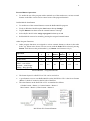
Other program functions are assigned to various external buttons as shown in the table
below (eg: When in the Setout Selection screen with the Point ID list selected, pressing
Button 1 will decrease the point number by 10, Button 3 will increase it by 5)
Operation
Any Point Number Selection
Pt Increment
Auto Interval
ARef – Auto Offset
AGrade – Auto Height
ARing – Ring Spacing
Button
1
-10
Button
2
-5
-2
-1
-1.0
-0.5
Left
Button
-1
Right
Button
+1
Change Sign -/+
-0.1
+0.1
Button
3
+5
Button
4
+10
+1
+2
+0.5
+1.0
External Buttons - Assigned Functions
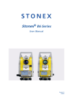
The button layout for a Dell X50 or X51 can be seen below
A good button to use to start RefSet Mobile on the Dell X50 or X51 is the Record button
(Button 5) which is located on the left side of the PDA
The other buttons on the Dell X50 or X51 are numbered as follows
Calender button = Button 1, Contacts button = Button 2
Inbox button = Button 3, Home button = Button 4
Dell X50 & X51 External Buttons
7
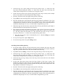
4. Refline
With RefSet Mobile connected to the TPS
Tap or select Refline on the start menu screen
The Refline Selection screen will then be shown
Select the Data Job to use from the list
Select the Start Point and End Point of the refline from the lists OR
Select either the Start Point or the End Point list box
To enter the point coordinates from the keyboard - tap Input and then enter the new
Point ID and coordinates for the selected point, then tap Cont, the new point will
then be stored in the data file
To measure a point - tap Meas, then at the Measure Point screen, enter the new Point
ID and then point the TPS to the point to measure and make sure a distance has been
measured, then tap Cont, the new point will then be stored in the data file
To manually enter a grade for the refline, select Y for Enter Grade?, then enter the grade
to use (eg: 50 for up at 1 in 50 or -50 for down at 1 in 50). The refline will then go from
the start point elevation towards the end point at the entered grade
To display the refline details and the start and end point coordinates, tap on Info
To start the refline measurement, tap Cont
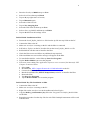
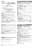
Refline Selection Screen
Main Refline Screen
(Showing Start Point selected for Input or Meas)
Tap NewLine to return to the Refline Selection screen to enter new refline points
Tap NextLine to go to the next refline by incrementing the refline start and end points by
the Pt Increment value (eg: if Pt Increment is 1 then refline will change from 1-2 to 2-3,
if Pt Increment is 2 then refline will change from 1-2 to 3-4, if Pt Increment is -1 then
refline will change from 2-3 to 1-2)
Tap Shift then Quit to exit refline and return to the main menu screen
8
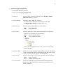
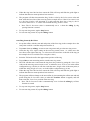
Auto Refline Screen
Auto Hole Screen
Auto Grade Screen
Auto Grade Line Setout
Set up the refline start and end points using the design string points or use the Meas
function to measure the points and then manually enter a grade in the Refline Selection
screen, to extend an existing grade line if no design is to be used (eg: ore drives)
Tap Auto+ then tap AGrade+ to turn on auto grade and go to the auto grade screen
Check the Auto Height setting and set to the refline height offset that is to be set out (eg:
1.500 for a grade line 1.5m above the design)
Point the TPS at the wall at the approximate position to start the setout and then tap on
Dist to start measuring and start the auto grade setout
The TPS will then move and setout the ^Height value that has been set in the Auto Height
setting (eg: 1.500), to within the AGrade Height Accuracy set in the refline configuration
(eg: 0.025m) , near the start position
When the refline has been setout the TPS will beep and flash the guide light to indicate
that the auto setout point has been reached
The TPS will then move along the refline at the set Auto Interval value (eg: 1.0m
intervals), and setout each interval
At the end point of the refline the auto setout function will respond according to the
setting in End Of Line on the auto grade screen
If set to Continue the auto setout will continue past the ref line end point
If set to Stop the auto setout will stop near the ref line end point
If set to Next Line the auto setout will stop near the ref line end point, then will
change to the next refline by incrementing the refline start and end points using the
Pt Increment value (as when the NextLine button is tapped), auto grade setout will
then continue using the new refline and setout the Auto Height value
To stop auto grade setout, tap the Stop button
To turn auto grade setout off, tap the AGrade- button
9
Auto Refline Setout
Tap Auto+ then tap ARef+ to turn on auto refline setout and go to the auto refline screen
Check the Auto Offset setting and set to the refline offset that is to be set out (eg: 0.000
for the centreline)
Point the TPS at the wall or backs at the approximate position to start the setout and then
tap on Dist to start measuring and start the auto refline setout
The TPS will then move and setout the ^Offset value that has been set in the Auto Offset
setting (eg: 0.000), to within the Auto Accuracy set in the refline configuration (eg:
0.025m), near the start position
When the refline has been setout the TPS will beep and flash the guide light to indicate
that the auto setout point has been reached
The TPS will then move along the refline at the set Auto Interval value (eg: 1.0m
intervals), and setout each interval
At the end point of the refline the auto setout function will respond according to the
setting in End Of Line on the auto refline screen
If set to Continue the auto setout will continue past the refline end point
If set to Stop the auto setout will stop near the refline end point
If set to Next Line the auto setout will stop near the refline end point, then will change
to the next refline by incrementing the refline start and end points using the Pt
Increment value (as when the NextLine button is tapped), auto refline setout will
then continue using the new refline and setout the Auto Offset value
To stop auto refline setout, tap the Stop button
To turn auto refline setout off, tap the ARef- button
Auto Hole Setout
Set up the refline start and end points to be the collar and toe points of the drill hole
Tap Auto+ then tap AHole+ to turn on auto hole setout and go to the auto hole screen
Point the TPS at the wall or backs at the approximate position of the hole
Tap on Dist to start measuring and to start the auto hole setout
The TPS will then move and setout the hole collar position by getting the ^Offset and
^Perp Ht values on the auto hole setout screen to zero, within the Auto Accuracy set in
the refline configuration (eg: 0.025m)
When the hole has been setout the TPS will beep and flash the guide light to indicate that
the auto setout point has been reached
The program will then change to the next refline by incrementing the refline start and end
points using the Pt Increment value (as when the NextLine button is tapped), and will
then setout the collar position of that hole
Note: The Pt Increment value is set to 2 when the AHole function is started
To stop auto hole setout, tap the Stop button
To turn auto hole setout off, tap the AHole- button
10
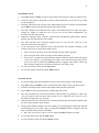
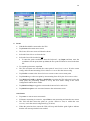
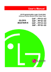
ARing by Ref Points Screen
ARing by Ring Spacing Screen
ARing by Ref Lines Screen
Auto Ring Setout
The auto ring setout method can be set in the Refline Configuration and the setup of the
data points for each method can be seen in the examples below.
The Ref Points method needs a point for the start and end of the refline and reference
points somewhere on each ring, these points do not have to be on the centreline
The Ring Spacing method only requires a point for the start and end points of the refline,
however the start point needs to be on the first ring and the ring spacing needs to be
consistent for the entire ring markup. The point number of the start point should also
match the ring number of the first ring if possible.
The Ref Lines method needs two points for each ring line and needs to follow a
consistent numbering system (eg: all the start points to the right of the refline and all the
end points to the left of the refline)
ARing by Ref Points
ARing by Ring Spacing
ARing by Ref Lines
Auto Ring Setout by Ref Points
Set up the refline with the start and end points (in the example above the start point
would be 1 and the end point would be 7)
Tap Auto+ then tap ARing+ to turn on auto ring setout and go to the auto ring screen
11
Check the Rig Laser Offset setting on the auto ring setout screen, +ve values move the
laser lines forward along the refline, -ve values move the laser lines back along the
refline (in the example above it would be set to a negative value)
On the auto ring setout screen select the Ring RefPt of the ring to setout (in the example
above set it to point 2 to start setting out the rings at ring 1)
Point the TPS at the wall at the approximate position of the ring
Tap on Dist to start measuring and to start the auto ring setout
The TPS will then move and setout the ring laser line position by getting the ^Laser Line
value on the auto ring setout screen to zero, to within the Auto Accuracy set in the refline
configuration (eg: 0.025m), it will also setout the same ^Height value as the start point, to
within the ARing Height Accuracy set in the refline configuration (eg: 0.2m)
When the ring laser line has been setout the TPS will beep and flash the guide light to
indicate that the auto setout point has been reached
The program will then increment the Ring RefPt value by the Pt Increment value and
then setout the laser line of the next ring (in the example above if the Pt Increment is set
to 1 the Ring RefPt will increment to 3 and setout the laser line of ring 2), the Pt
Increment can be set to –ve values to decrement the Ring RefPt values
Note: The Pt Increment value is automatically set to 1 when the ARing by ref points
function is started
To stop auto ring setout, tap the Stop button
To turn auto ring setout off, tap the ARing- button
Auto Ring Setout by Ring Spacing
Set up the refline with the start and end points (in the example above the start point
would be 1 and the end point would be 2), the start point needs to be located on the first
ring and if possible needs to have the same number as the first ring
Tap Auto+ then tap ARing+ to turn on auto ring setout and go to the auto ring screen
Check the Rig Laser Offset setting on the auto ring setout screen, +ve values move the
laser lines forward along the refline, -ve values move the laser lines back along the
refline (in the example above it would be set to a negative value)
Check the Ring Spacing setting on the auto ring setout screen and set to the distance
between the rings
On the auto ring setout screen select the Ring Number of the ring to setout. The
numbering of the rings starts from the start point number and increases towards the end
point for the number of rings between the start and end point (in the example above the
ring numbers would start at 1 and go to 5)
Point the TPS at the wall at the approximate position of the ring
Tap on Dist to start measuring and to start the auto ring setout
The TPS will then move and setout the ring laser line position by getting the ^Laser Line
value on the auto ring setout screen to zero, to within the Auto Accuracy set in the refline
configuration (eg: 0.025m), it will also setout the same ^Height value as the start point, to
within the ARing Height Accuracy set in the refline configuration (eg: 0.2m)
12
When the ring laser line has been setout the TPS will beep and flash the guide light to
indicate that the auto setout point has been reached
The program will then increment the Ring Number value by the Pt Increment value and
then setout the laser line of the next ring (in the example above if the Pt Increment is set
to 1 the Ring Number will increment to 2 and setout the laser line of ring 2), the Pt
Increment can be set to –ve values to decrement the Ring Number values
Note: The Pt Increment value is automatically set to 1 when the ARing by ring
spacing function is started
To stop auto ring setout, tap the Stop button
To turn auto ring setout off, tap the ARing- button
Auto Ring Setout by Ref Lines
Set up the refline with the start and end points of the first ring (in the example above the
start point would be 1 and the end point would be 2)
Tap Auto+ then tap ARing+ to turn on auto ring setout and go to the auto ring screen
Check the Rig Laser Offset setting on the auto ring setout screen, +ve values move the
laser lines to the right of the ring, -ve values move the laser lines to the left of the ring (in
the example above it would be set to a negative value)
Point the TPS at the wall at the approximate position of the ring
Tap on Dist to start measuring and to start the auto ring setout
The TPS will then move and setout the ring laser line position by getting the ^Laser Line
value on the auto ring setout screen to zero, to within the Auto Accuracy set in the refline
configuration (eg: 0.025m), it will also setout the same ^Height value as the start point, to
within the ARing Height Accuracy set in the refline configuration (eg: 0.2m)
When the ring laser line has been setout the TPS will beep and flash the guide light to
indicate that the auto setout point has been reached
The program will then change to the next refline by incrementing the refline start and end
points using the Pt Increment value (as when the NextLine button is tapped), and will
then setout the ^Laser Line position of the next ring
Note: The Pt Increment value is automatically set to 2 when the ARing by ref lines
function is started
To stop auto ring setout, tap the Stop button
To turn auto ring setout off, tap the ARing- button
13
5. Refline Configuration Settings
EDM Program
The EDM program to use in refline
RL-TRK
RL-STD
Reflectorless tracking
Reflectorless standard
Start Measure?
Start distance measuring when refline starts
Auto Accuracy
Sets the accuracy at which points are setout in auto modes (eg: if set
to 0.025 the TPS will get the points to within 25mm before moving
to the next point)
ARing Height Acc
Sets the accuracy at which the ^Height is setout in the ARing mode
(eg: if set to 0.200 the TPS will setout the laser lines to within
200mm of the ^Height of the first laser line setout)
AGrade Height Acc
Sets the accuracy at which the ^Height is setout in the AGrade mode
Auto Wait (secs)
Sets the time the TPS will stop on an auto setout point (eg: if set to
5 the TPS will wait 5 seconds after it sets out a point before it
moves on to the next point)
Auto Interval
Sets the interval between setout points in the ARef and AGrade
modes
ARef S/O Offset
The default Auto Offset value to setout in auto refline mode
AGrade S/O Height
The default Auto Height value to setout in auto grade mode
Auto End Of Line
Sets the behaviour of the auto setout mode when the end of the
refline is reached in the ARef and AGrade modes
Stop
Stops auto setout at the end of the refline
Continue Continues auto setout past the end of the refline
Next Line Increments to the next refline at the end of the current
refline
Auto Ring Method
The ring setout method in auto ring mode
Rig Laser O/S
The default Rig Laser O/S value in auto ring mode
Ring Spacing
The default Ring Spacing value in auto ring mode
14
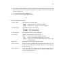
Setout Selection Screen
Polar Setout Screen
Ortho Setout with Auto on
6. Setout
With RefSet Mobile connected to the TPS
Tap Setout on the main menu screen
The Setout Selection screen will then be shown
Select the Data Job to use from the list
Select the Point ID from the list OR
To enter the point coordinates from the keyboard - tap Input and then enter the
coordinates for the point, then tap Cont, the new point will then be stored in the data
file
To start the point setout, tap Cont
The TPS will then turn towards the setout point if Auto Posit is set to Y in the setout
config, and will start measuring if Start Measure is set to Y in the setout config
Tap NewPt to return to the Setout Selection screen to enter a new setout point
Tap NextPt to go to the next point by incrementing Point ID by the Pt Increment value
Tap Shift then Pos2D (or Pos3D or PosPP3D) to position the TPS telescope back to the
setout point, the positioning method is set by the Posit Mode setting in the setout
configuration and has three modes
Tap Shift then Disp to toggle the setout mode between Polar and Ortho
Tap Shift then Quit to exit setout and return to the main menu screen
Auto Setout
Tap Auto+ to turn on auto setout mode
If distance measuring is not active, tap on Dist to start measuring and start the auto setout
The TPS will then setout the point (ie: get the ^HDist to zero) to within the Auto
Accuracy set in the setout configuration (eg: 0.025m)
When the point has been setout the TPS will beep and flash the guide light to indicate
that the auto setout point has been reached
15
The program will then change to the next setout point by incrementing the Point ID using
the Pt Increment value (as when the NxtPt button is tapped), and will then setout the
position of that point
To stop auto setout, tap the Stop button
To turn auto setout off, tap the Auto- button
7. Setout Configuration Settings
Default Mode
The default setout display mode
Polar
Ortho
EDM Program
Display shows ^Hz, ^HDist and ^Height
Display shows ^Length, ^Cross and ^Height
The EDM program to use in setout
RL-TRK
RL-STD
Reflectorless tracking
Reflectorless standard
Start Measure?
Start distance measuring when setout starts
Posit Mode
Method of positioning the TPS telescope
2D
3D
PP3D
Setout point using horizontal coords only
Setout point using horizontal and vertical coords
Setout point using horizontal coords and vertical coord
of previous point
Auto Posit
Position the TPS telescope when setout starts
Auto Accuracy
Sets the accuracy at which points are setout in auto modes (eg: if set
to 0.025 the TPS will get the points to within 25mm before moving
to the next point)
Auto Wait (secs)
Sets the time the TPS will stop on an auto setout point (eg: if set to
5 the TPS will wait 5 seconds after it sets out a point before it
moves on to the next point)