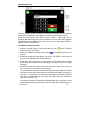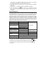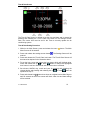
1
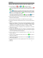
User Manual for
AGMA & AGA Model
Zone Controller
V2. 08/10/2009
0
Contents
Introduction ........................................................................................................... 2 Turning System to Standby or On .................................................................. 3 Turning System Off ......................................................................................... 3 Reactivating a Blank Screen ........................................................................... 3 Main Screen.......................................................................................................... 4 Selecting Compressor Mode of Operation...................................................... 4 Selecting Fan Mode of Operation ................................................................... 4 Adjusting Controllers Zone Set Point .............................................................. 4 Entering Main Menu Screen ........................................................................... 4 Main Menu Screen ................................................................................................ 6 Zones Screen ....................................................................................................... 7 Timers Screen ...................................................................................................... 8 Timer Programming & Enabling Procedure .................................................... 9 Disabling Timer ............................................................................................... 9 Lock Screen ........................................................................................................ 10 Sleep Timer ........................................................................................................ 11 Wake Timer ........................................................................................................ 12 Settings Screen .................................................................................................. 13 Zone Names Screen ..................................................................................... 14 Zone Name Change Procedure ................................................................ 14 System Settings Screen................................................................................ 15 Time & Date Screen...................................................................................... 16 Time & Date Setting Procedure ................................................................ 16 System Status Screen .................................................................................. 17 System Logs Screen ..................................................................................... 18 V1.2 08/10/2009
1
Introduction
AGMA and AGA model Zone Controllers provide user interface to the air
conditioning control system allowing the user to perform the following functions:
a) Turn the system to off
, standby
or on
mode (refer to page 3).
To turn the system completely off the controller should be switched to off
mode which ensures that no other automatic function will switch the unit to on
mode.
Standby
mode does not completely shut down the system, it allows the unit
to turn on for Min/Max temperature (override) operation whilst still in standby
mode or to automatically switch to on
mode if a timer setting requires the
unit to turn on or if the Wake Timer lapses.
The system will automatically switch from on
mode to standby
mode if a
timer setting requires the system to turn off or if the Sleep Timer lapses.
b) Select cooling, heating, auto or fan only compressor mode of operation in the
Main Screen (refer to page 4).
c) Select fan speed mode of operation in the Main Screen (refer to page 4).
d) Activate and de-activate individual ducted zones in the Zones Screen (refer to
page 7).
e) Display the controllers’ zone set point and current temperature in the Main
Screen (refer to page 4). The set point is the target temperature the air
conditioner will try to maintain the zone at by heating or cooling towards
(depending upon compressor mode of operation i.e. heating or cooling).
f) Adjust all zone set points and display all zone temperatures in the Zones
Screen (refer to page 7).
g) Program and enable/disable daily timer settings for automatically activating
and de-activating the air conditioning system (refer to Timer Screen on page 8
and Timer Programming Procedure on page 9).
h) Lock the system to prevent unauthorised access to menus (refer to Lock
Screen on page 10).
i) Activate a sleep countdown timer when the unit is in on
Sleep Timer on page 11).
j) Activate a wake countdown timer when the unit is in standby
Wake Timer on page 12).
mode (refer to
mode (refer to
k) Set system date and time for timer operation (refer to Time & Date Screen on
page 16).
V1.2 08/10/2009
2
l) Enable/Disable Min/Max temperature operation and configure Min/Max
temperature operation minimum and maximum set points in the System
Settings Screen (refer to page 15). This feature allows the air conditioning
system to turn itself on during standby mode to maintain room temperature
above minimum and below maximum Min/Max temperature set points. This
reduces the required time to reach zone set point when the unit is later turned
on.
m) Configure multiple system settings and parameters in the Settings Screen
(refer to page 13).
n) View time stamps of system events in the System Logs Screen – For Installer
and Service Technicians only (refer to page 18).
Turning System to Standby or On
1. Press and hold
button for 5 seconds then release. Power button will change
to . System is now in standby mode.
2. Press and release
button. Power button will change to . System is now in
on mode and will operate according to configured settings.
Turning System Off
Whilst in On Mode
1. Whilst power button shows , press and release
button. Power button will
change to . System is now in standby mode.
2. Press and hold
button for 5 seconds then release. Power button will change
to . System is now in off mode.
Whilst in Standby Mode
1. Whilst power button shows , Press and hold
button for 5 seconds then
release. Power button will change to . System is now in off mode.
Reactivating a Blank Screen
If any part of the screen (or any button) is not touched within 50 seconds
screen will turn off (go blank). Any changes made before the screen blanks
be retained. A blank screen can be reactivated by touching any part of
screen. When reactivated, the Main Screen will always be displayed except if
Lock Screen was entered in which case the Lock Screen will be displayed.
V1.2 08/10/2009
3
the
will
the
the
Main Screen
The Main Screen appears when power is first applied to the unit, when navigating
back from the Main Menu Screen or when reactivating a blank screen (except
when in Lock screen). Refer to Main Screen Legend on page 5 for mode, button
and indicator descriptions and explanations.
Selecting Compressor Mode of Operation
Press and release the compressor mode button to cycle between auto
only , cooling
or heating
modes of compressor operation.
, fan
Selecting Fan Mode of Operation
Press and release the fan mode button to cycle between low
or auto
modes of fan operation.
, medium
, high
Adjusting Controllers Zone Set Point
Whilst in the Main screen the zone set point can be adjusted up or down only for
the zone the controller is installed in. Other zone set points can be adjusted in the
Zones Screen (refer to page 7).
To increase zone set point, press & release the
button. The set point will
increase by 0.5ºC increments for each press and release up to a max of 35ºC.
To decrease zone set point, press & release the
button. The set point will
decrease by 0.5ºC increments for each press and release down to a min of 10ºC.
Entering Main Menu Screen
1. To enter the Main Menu Screen Press and release the menu
to page 6 for Main Menu Screen information and operation.
V1.2 08/10/2009
button. Refer
4
Main Screen Legend
Item
Indication
ON mode: System is actively controlling
temperature.
Standby mode: This is the default state when
system has either reached target temperature
(including during Min/Max operation) or is
outside programmed ‘wake’ or ‘on’ times.
Off mode: System is off and not controlling
temperature.
Power button
Time
i di i
Set point
Set point up
button
Set point down
button
Compressor
mode button
Meaning
--:-- AM or PM
ºC
Displays current time (if set)
Displays current set point for zone controller
is installed in.
Each press & release adjusts set point for
zone controller is installed in down by 0.5ºC
increments to a min of 10ºC.
Each press & release adjusts set point for
zone controller is installed in up by 0.5ºC
increments to a max of 35ºC.
Cooling mode: System is configured to cool
zone down towards the set point temperature.
Heating mode: System is configured to heat
zone up towards the set point temperature.
Auto mode: System dynamically heats and
cools zone to maintain temperature at set
point.
Fan only mode: Only fan is operational. Zone
damper & fan speed are controlled by
temperature if fan setting is on Auto.
Low: Sets fan to low speed setting.
Fan mode
button
Med: Sets fan to medium speed setting.
High: Sets fan to high speed setting.
Auto: Adjusts fan speed
temperature differential.
Menu button
V1.2 08/10/2009
according
to
Press and release to enter Main Menu
Screen.
5
Main Menu Screen
The Main Menu Screen is entered by pressing and releasing the menu
button
on the Main Screen. The Main Menu Screen provides push button access to the
sub system menu screens and Sleep or Wake Timer.
To enter a sub system menu screen or timer, press and release the relevant
screen or timer button.
To navigate back to the Main Screen press and release back
button.
Refer to the following pages for sub system menu screen and timer information
and operation:
Zones Screen................................................................................................page 7.
Timers Screen...............................................................................................page 8.
Lock Screen................................................................................................page 10.
Sleep Timer.................................................................................................page 11.
Wake Timer.................................................................................................page 12.
Settings Screen...........................................................................................page 13.
Main Menu Screen Notes
If the system is in on mode
illustration above.
the sleep timer button will be as shown in the
If the system is in standby
mode the sleep timer button will be
replaced by the wake timer button as shown opposite.
If the system is in off mode
for selection.
V1.2 08/10/2009
the sleep or wake timer button will not be available
6
Zones Screen
The Zones Screen is entered by pressing and releasing the zones screen
button on the Main Menu Screen.
The Zones Screen displays the current set point for each zone and the
temperature reading in each zone. 2 zones are displayed per page.
Zones can be enabled and disabled by pressing and releasing the zone name
button (i.e. zone 1 button). When a zone is enabled, all text information relating to
that zone is white as shown in the illustration above. When a zone is disabled, all
text information relating to that zone is greyed out.
To increase a zone set point, press & release the relevant zones set point up
button. The set point will increase by 0.5ºC increments for each press and release
up to a maximum of 35ºC.
To decrease a zone set point, press & release the relevant zones set point down
button. The set point will decrease by 0.5ºC increments for each press and
release down to a minimum of 10ºC.
To navigate to the next zone page press and release next zone page
button.
To navigate to the previous zone page press and release previous zone
To navigate back to the Main Menu Screen press and release back
button.
button.
Zones Screen Notes
If system cannot read a zone temperature due to any error, the zone thermometer
icon and zone temperature reading for the affected zone will not be displayed.
V1.2 08/10/2009
7
Timers Screen
The Timers Screen is a 7 day timer which is entered by pressing and releasing
the timers screen
button on the Main Menu Screen.
The Timers Screen is utilised to configure daily timer settings for automatic
activation and de-activation of the air conditioning system whilst operating in on
or standby
mode. Note: The system will automatically switch from on
to
mode if the timer setting is enabled and the programmed time requires
standby
the system to turn off.
The Timers Screen has 7 screen pages, one screen page for each day of the
week which is broken into two sections; top half for AM and bottom half for PM.
Solid green areas of an hour button represent an on period whilst black areas of
an hour button represent an off period.
The left hand half of an hour button is the first half of the hour whilst the right hand
half of an hour button is the second half of the hour.
Each press and release of an hour button will change that hour button in half hour
increments. There are four possible values for each hour button which are as
follows:
The system is off from 3:00 – 3:59.
The system is on from 3:00 – 3:29 and off from 3:30 to 3:59.
The system is off from 3:00 – 3:29 and on from 3:30 – 3:59.
The system is on from 3:00 – 3:59.
To program and enable the timer, follow the procedure on page 9.
V1.2 08/10/2009
8
Timer Programming Example
In the illustration shown at the top of page 8, the timer will turn on on Tuesday at
2:00AM and will turn off at 3:59AM. The timer will then turn back on at 2:00PM
and will turn off at 3:59PM.
Timer Programming & Enabling Procedure
1. Whilst in the Main Screen, press and release the menu
Menu Screen will be entered.
2. Press and release timers screen
button. The Main
button. The Timer Screen will be entered.
3. Set timer on and off periods for current day page by pressing and releasing
relevant hour buttons as previously explained on page 8.
button to navigate to the next day page and
4. Press and release next day
program times in the same manner.
5. Follow step 2 for each day of the week. Note if operation is not required for
any day of the week leave all hour buttons black.
6. Navigate back to Main Menu Screen by pressing and releasing back
button.
7. Navigate to Settings Screen by pressing and releasing settings screen
button.
8. Press and release ‘System Settings’ text to enter the System Settings Screen.
9. Press and release the
press and release).
button three times (screen will change with each
10. If ‘enabled’ is shown after ‘Timers’ text the timer system is already enabled in
which case proceed to step 9. If ‘disabled’ is shown after ‘Timers’ text press
and release ‘Timers’ text and ‘disabled’ will change to show ‘enabled’.
11. Set system to standby
page 3.
mode by operating the power button as explained on
12. Timer has now been set and enabled. Press back
button two times to
navigate back to Main Screen or wait 50 seconds at which time screen will
blank out. Programmed settings will be retained and system will operate
according to programmed times.
Disabling Timer
To activate system in a timer off period, select on
mode by operating the power
button as explained on page 4. To disable timer whilst retaining timer settings,
select ‘disable’ after ‘Timers’ text in settings menu by following steps 4 – 8 of
mode by operating the power button
above procedure then turn system to on
as explained on page 4. System will then be activated and air conditioner will
operate regardless of timer settings.
V1.2 08/10/2009
9
Lock Screen
The Lock Screen is entered by pressing and releasing the lock screen
on the Main Menu Screen.
button
Once the Lock Screen has been entered the controller will remain on the lock screen
until the correct security code has been typed in and the enter button pressed and
released. Whilst in the Lock Screen the system will operate as configured and the
power button can be operated however access to all other screens and menus is
prevented.
If an incorrect security code is entered and the enter button pressed and released
the code entry indicator will display WRONG CODE at which time the correct
security code will need to be re-entered and the enter button pressed and
released. When the correct security code is entered the system will unlock and
the Main Menu Screen will be displayed.
If an incorrect digit is entered the clear button can be pressed and released to
clear the last entered digit.
The default security code is 12345.
The security code can be changed by pressing and releasing the ‘Set Security
Code’ text button in the ‘System Settings Screen’ and following the on screen
prompts (refer to page 15).
V1.2 08/10/2009
10
Sleep Timer
The Sleep Timer is a countdown type timer which is activated by pressing and
releasing the sleep timer
button on the Main Menu Screen. Note: The sleep
timer button cannot be selected from the Main Menu Screen unless the system is
in on
mode. If the system is in standby
mode the sleep timer button will be
replaced by the wake timer
button.
Each press and release of the sleep timer
button will activate the sleep time
indicator in half hour increments up to a maximum of 12.5 hours. The sleep time
indicator will be displayed at the top of the Main Menu Screen and Main Screen.
When the sleep time indicator counts down to 00:00 the system will change from
on
mode to standby
mode and the air conditioner will be de-activated.
To cancel a sleep time setting, continuously press and release the sleep timer
button
until the sleep time indicator disappears (one press and release after
12:30).
To navigate back to the Main Screen press and release the back
V1.2 08/10/2009
button.
11
Wake Timer
The Wake Timer is a countdown type timer which is activated by pressing and
releasing the wake timer
button on the Main Menu Screen. Note: The wake
timer button cannot be selected from the Main Menu Screen unless the system is
in standby
mode. If the system is in on
mode the wake timer button will be
replaced by the sleep timer
button.
Each press and release of the wake timer
button will activate the wake time
indicator in half hour increments up to a maximum of 12.5 hours. The wake time
indicator will be displayed at the top of the Main Menu Screen and Main Screen.
When the wake time indicator counts down to 00:00 the system will change from
standby
mode to on
mode and the air conditioner will be activated and
operate according to configured settings.
To cancel a wake time setting, continuously press and release the wake timer
button
until the wake time indicator disappears (one press and release after
12:30).
To navigate back to the Main Menu Screen press and release the back
button.
V1.2 08/10/2009
12
Settings Screen
The Settings Screen is entered by pressing and releasing the settings screen
button on the Main Menu Screen.
The Settings Screen provides access to sub setting menu screens as depicted in
the diagram above.
To enter a sub setting menu screen press and release the relevant sub setting
menu text button.
To navigate back to the Main Menu Screen press and release the back
button.
Refer to the following pages for sub system menu screen information and
operation:
Zone Names Screen...................................................................................page 14.
System Settings Screen..............................................................................page 15.
Time & Date Screen....................................................................................page 16.
System Status Screen................................................................................page 17.
System Logs Screen...................................................................................page 18.
V1.2 08/10/2009
13
Zone Names Screen
The Zone Names Screen is utilised to change zone names and is entered by
pressing and releasing the ‘Zone Names’ text button on the Settings Screen.
When first entering the Zone Names Screen, ZONE 1 name page will be
displayed with the existing zone name indicated in the zone name entry indicator
as depicted in the illustration above. There are four zone name pages (ZONE 1,
ZONE 2, ZONE 3 and ZONE 4).
Zone Name Change Procedure
1. Whilst in the Main Screen, press and release the menu
Menu Screen will be entered.
2. Press and release the settings screen button
entered.
button. The Main
. The Settings Screen will be
3. Press and release the ‘Zone Names’ text button. The ZONE 1 name page will
be entered as depicted in the illustration above.
4. Continually press and release the clear button until all existing text is erased
(each press and release of the clear button will erase the previous single
text/digit).
5. Press and release text buttons to enter the new zone 1 name. Zone names can
have a maximum of 8 characters including spaces.
To cycle between text button values continually press and release the relevant
text button ensuring the delay between each press and release is less than 3
seconds, i.e. if text button 2 is pressed and released four times with a delay of
less than 3 seconds between each press and release the value entered will
cycle from A to B to C to 1.
If the same text button is pressed and released twice with a 3 second or more
delay between each press and release the first value will be entered twice, i.e.
V1.2 08/10/2009
14
if text button 2 is pressed and released twice with a delay of 3 seconds or
more between each press and release AA will be entered.
6. Press and release the next zone button. The screen will advance to ZONE 2
name page.
7. Repeat steps 3 – 5 for ZONE 2, ZONE 3 and ZONE 4 name pages.
button three times to navigate back to Main
8. Press and release the back
Page or wait 50 seconds at which time screen will blank. New zone names will
be retained.
System Settings Screen
The System Settings Screen is utilised for initial set up by Installer and for
enabling/disabling timers, changing the security code, enabling/disabling Min/Max
temperature operation and adjusting Min/Max temperature operation set points.
The System Settings Screen is entered by pressing and releasing the ‘System
Settings’ text button on the Settings Screen and is comprised of five pages
containing settings which can be altered by pressing and releasing the relevant
setting name to cycle through possible values. The table shown below details the
settings and possible values or procedures available.
Setting Name
Unit ID
Number of Zones
Defrost Delay (minutes)
Indoor Fan Cycling
Outdoor Fan Speed hi
Outdoor Fan Speed lo
Min/Max Temperature
Min Temperature
Max Temperature
Timers
Calibrate Touchscreen
Set Security Code
Reset Control Settings
Possible Values
Details
1 – (number of zones)
1–8
20 – 30
Set by Installer
normal
cycling
continuous
Outdoor fan speed lo – 50
05 – Outdoor fan speed hi
enabled
Enables/disables
Min/Max temp function
disabled
10 degrees – Max Temp
Min/Max min set point
Min Temp – 35 degrees
Min/Max max set point
Activates time clock
enabled
disabled
Deactivates time clock
Puts user through touchscreen calib procedure
Puts user through change security code procedure
Resets controller to default values
To navigate to the next system settings page press and release the
button.
To navigate to the previous system settings page press and release the
To navigate back to the Main Menu Screen press and release back
V1.2 08/10/2009
button.
button.
15
Time & Date Screen
The Time & Date Screen is utilised to set the time and date and is entered by
pressing and releasing the ‘Time & Date’ text button on the Settings Screen.
Note: The correct time must be set for the Timer to correctly operate the air
conditioning system.
Time & Date Setting Procedure
1. Whilst in the Main Screen, press and release the menu
Menu Screen will be entered.
2. Press and release the settings screen button
entered.
button. The Main
. The Settings Screen will be
3. Press and release the ‘Time & Date’ text button. The Time & Date Screen will
be entered as depicted in the illustration above.
4. To set the hour, press and release the hour button which will highlight white.
Press and release the up
or down
button to change the highlighted
hour button in one hour increments until the correct hour is reached.
5. Set minutes, AM/PM, day, month and year by pressing and releasing the
relevant button and pressing and releasing the up
or down
button as
explained in step 4.
6. Press and release back button three times to navigate back to Main Page or
wait 50 seconds at which time screen will blank. New time and date settings
will be retained.
V1.2 08/10/2009
16
System Status Screen
The System Status Screen is provided for the Installer or Service Technician and
is utilised to check the current operating status of the system.
The Systems Status Screen is entered by pressing and releasing the ‘System
Status’ text button on the Settings Screen.
The table shown below details system status items and possible values available.
Item
Compressor
Reverse Valve
De-Ice
Comp Duty
Outdoor Fan
Outdoor Temp
Indoor Fan
OT
HP
LP
Min/Max
Possible Values
On
Off
On
Off
Active
Inactive
0 – 100%
0 – 100%
-10 – 100 deg
Off
Low
Med
High
Active
Inactive
Active
Inactive
Active
Inactive
Active
Inactive
Details
Compressor operating status
Reversing valve operating status
De-ice function operating status
Compressor duty
Outdoor fan duty
Outdoor evap or condenser temp
Indoor fan operating status
Active = compressor OT error condition.
Active = system HP error condition. To
reset press & release ‘HP’
Active = system LP error condition. To
reset press & release ‘LP’
Min/Max operation operating status
To navigate back to the Main Menu Screen press and release back
V1.2 08/10/2009
button.
17
System Logs Screen
The System Logs Screen provides a time stamp of certain system events and is
provided for the Installer or Service Technician.
The System Logs Screen is entered by pressing and releasing the ‘System Logs’
text button on the Settings Screen.
The table shown below details system events that are time stamped.
Event
High Pressure
Low Pressure
De-ice
Min/Max Temperature
Compressor
Reversing Valve
Compressor Over Temperature
Details
When a HP state was detected or cleared
When a LP state was detected or cleared
When De-ice operation started or finished
When system was activated or deactivated
due to Min/Max temperature function
When compressor operation started or
finished
When reversing valve was activated or
deactivated
When compressor over temperate (OT)
state was detected or cleared
To navigate back to the Main Menu Screen press and release back
V1.2 08/10/2009
button.
18