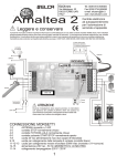
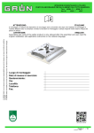
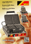
1
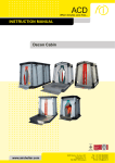
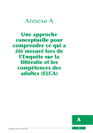
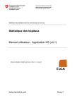
ING_Man_MITO-A-MINI_00.doc
Radio Remote Control System MITO-A-MINI
1. USER MANUAL.
Read this manual before using the radio control.
To make the manual easier to consult, each section title is accompanied by a sign as a guide to the importance of the
information given in the section.
SIGN
MEANING
IMPORTANT!
How to use the Radio control properly: Radio control user instructions.
About the Radio control: Radio control technical data.
Really know how to use the Radio control: Radio control details.
IMPORTANT ANNEXES!
Legal paperwork when using the radio control: instruction on compliance with statutory regulations.
What’s more any parts requiring special care are in bold print.
This manual can be changed without notice and is solely a guideline provided by Elca.
This edition has been updated with the help of feedback received from our customers, so it can be considered a very
valid aid for their work.
This manual and any annex are property of ELCA with all rights reserved. Reproduction or transmission of any part of
this documentation is prohibited in any form or for any reason without prior authorisation from ELCA.
The ELCA logo is a registered trademark.
- Page 1 -
ING_Man_MITO-A-MINI_00.doc
Radio Remote Control System MITO-A-MINI
2. USER INSTRUCTIONS
2.1 GENERAL OVERVIEW
The ELCA MITO type radio control system is an innovative family of low power industrial radio controls, designed for
controlling appliances that do not require a safety category 1 Stop command.
The ELCA MITO type radio control system is made up of two main parts.
The transmitter unit (AT) that permits the operator convey to the receiver the sequence of digital data that makes up a
given command.
The receiver unit (AR) that decodes the sequence of digital data and converts it into the electrical impulses required by
the machine to actuate the command.
The use of electromagnetic waves means that the control system leaves the operator free to move around the machine:
in fact the transmitter unit does not require connecting cables, so the operator can stand away from the machine, in
perfect safety and in an optimum position for controlling the machine movements.
Each radio control uses a specific transmission telegram univocally programmed by the manufacturer and is not
modifiable, so each transmitter unit will only operate with its associated receiver unit and therefore will not interfere with
other radio controls. The working frequency is automatically selected when the transmitter is activated according
to availability and lack of disturbance and persistent radio disturbance will automatically trigger a frequency
change without interrupting operations.
- Page 2 -
ING_Man_MITO-A-MINI_00.doc
Radio Remote Control System MITO-A-MINI
2.2 THE KEYPAD CONTROLS
CHECK
CHECK
T9
T4
T9
T4
T10
T3
T10
T3
T11
T2
T11
T2
STOP
T12
T1
START
The left-hand diagram illustrates the keypad for the 6-function plus start & stop version.
Transmission begins when the Start key is pressed, after entering the Pin code if this has been programmed,
and ends when the Stop key is pressed or by auto-shutdown when no transmitter key is pressed for a set
time (default 3 minutes).
The right-hand diagram illustrates the keypad for the 8-function version.
With this version transmission begins when any key is pressed and ends if no key is pressed after approx.
10 seconds.
2.3 A CORRECT AND SAFE USE OF THE RADIO CONTROL SYSTEM.
IMPORTANT! The radio control operator must:
- Be very well acquainted with the functions and characteristics of both the Radio control and the
machine connected to the receiver unit.
- Watch all the machine movements actuated by the radio control.
- Shutdown the transmitter unit whenever work is suspended, even for a brief period. Do not rely on
the auto-shutdown function.
- Never leave the transmitter unit unattended.
- Remember that the transmitter unit can actuate the machine movements even if it is situated in an
enclosed place and a long way away from the receiver unit. Its improper use can cause severe
damage and injury.
- Never wash the units with a water spray, only use a damp cloth.
- Do not use it inside shielded locations (e.g. inside the drum of a concrete mixer).
Some of the more common functions:
Activation: On continuous transmission versions having Start and Stop keys, press the Start key and the
transmitter’s Check light on the transmitter will begin flashing. If a Pin code has been programmed this must
first be entered before the Start key is enabled.
On temporary transmission versions, without Start and Stop keys, press any key to activate the transmitter
and the Check light will begin flashing.
CAUTION!: The transmitter will only activate if the batteries have sufficient charge and if the receiver unit is
powered and operational.
Commands: Press the control keys related to the actions that the machine has to perform.
Shutdown: On continuous transmission versions press the Stop button and the transmitter’s Check light will
go out after about 2 seconds. On temporary transmission versions the transmitter will automatically
shutdown about 10 seconds after the last key has been released.
Auto-shutdown: Automatic shutdown of the transmitter when it is not being used. If this function is enabled
the transmitter will shutdown if no key is pressed for a set period of time. The default setting is 3 minutes.
Passive safety function: If there is an interruption in the radio link or radio interference is affecting all
available frequencies, the receiver unit will automatically shutdown.
- Page 3 -
ING_Man_MITO-A-MINI_00.doc
Radio Remote Control System MITO-A-MINI
Battery charge indicator: When the battery is normally charged the Check light will flash rapidly (1
flash/sec). When the battery charge is not sufficient to ensure a proper transmission of the commands, the
Check light will begin to flash slowly (about 1 flash every 2 seconds) for about 10 minutes before the
transmitter finally shuts down. When the low battery charge signal appears it is good practice to place the
machine in a safe mode, shutdown the transmitter unit and place it on the battery charger to charge it.
2.4 PROGRAMMABLE FUNCTIONS.
CHECK
CHECK
T9
T4
T9
T4
The keypad has the following programming options:
T10
T3
T10
T3
T11
T2
T11
T2
- Change frequency group
- Auto-shutdown time
- Pin code
- Lock key programming
T12
T1
T12
T1
Key attributions
•
Accessing the programming mode (Main Menu)
CHECK
T12
T1
CAUTION: It is good practice to always program the functions with the machinery shutdown or with the
receiver power shut-off to avoid accidental machine commands.
Shutdown the transmitter and then press T1 + T12 at the same time. At this stage the status LED will flash at
1Hz (on-off for equal times) and after 5 seconds the status LED will light up continuously. This indicates that
the main menu of the programming mode has been entered and the transmitter will no longer send
commands.
•
•
•
•
•
If a key is not pressed for 10 seconds the transmitter will quit the programming mode and shutdown.
The main menu can be exited at any moment by pressing key T1. The transmitter will quit the
programming mode and shutdown.
When any of the programming submenus is entered, the LED will give two rapid flashes in one
second. If a key is not pressed for 10 seconds the LED will stay on (i.e. main menu).
After making a selection in any of the submenus, the status LED will give 3 flashes at 1Hz and then
return to the main menu.
When in a submenu and no selection is required, to return to the main menu wait for the 10-second
time-out, this cannot be done manually.
- Page 4 -
ING_Man_MITO-A-MINI_00.doc
•
Radio Remote Control System MITO-A-MINI
Change frequency group
CHECK
T2
When in the main menu press T2 to enter the “Change Freq. “ submenu
8 different groups can be set, each with 3 frequencies, by pressing the keys given in the table below:
Group 1 def.( 434.100 – 434.325 – 434.600
MHz)
Group 2 (434.150 – 434.375 – 434.650 MHz)
Group 3 (434.225 – 434.450 – 434.700 MHz)
Group 4 (434.275 – 434.500 – 434.750 MHz)
Group 5 (434.125 – 434.350 – 434.625 MHz)
Group 6 (434.175 – 434.400 – 434.675 MHz)
Group 7 (434.250 – 434.475 – 434.725 MHz)
Group 8 (434.300 – 434.525 – 434.775 MHz)
•
Key T3
X
Key T4
X
Key T9
X
X
X
Key T10
Key T11
X
X
X
X
X
X
X
X
X
X
X
Auto-shutdown time
CHECK
When in the main menu press T3 to enter the Shutdown Time submenu.
T3
4 different times can be set by pressing the keys in the table below:
10 sec. ( set temp. tx mode ) (See Note)
3 min. – default ( only for cont. tx mode )
10 min. (only for cont. tx mode)
Off ( only for cont. tx mode)
Key T4
X
Key T9
Key T10
Key T11
X
X
X
NOTE: This setting changes the system configuration from Continuous Transmission (i.e. Start key to
activate radio link and Stop key to end) to Temporary Transmission where keys T1 and T12 are normal
function keys and transmission is activated by pressing any key, only ending after the 10 second time-out.
IMPORTANT: Remember to set the micro-switches on the base card with dip1=0n and dip2= 0ff for a
correct operation of the T1 and T12 relays.
- Page 5 -
ING_Man_MITO-A-MINI_00.doc
•
Radio Remote Control System MITO-A-MINI
Pin Code
When in the main menu press T4 to enter Pin Code submenu.
CHECK
T4
Now set a sequence of 3 different keys.
After the third key is pressed the setting is saved and the main menu is
automatically restored.
To eliminate the setting press T4 and then T1.
Note 1: This function can only be used for continuous transmission (No 10-second
auto-shutdown).
Note 2: The default setting is with no Pin code.
Note 3: If the pin code is forgotten a new keypad has to be programmed or the
lock keypad function has to be cancelled to be able to use the transmitter.
•
Command lock programming:
T9
CHECK
This will activate or interrupt the transmission of a channel by just pressing a key
once. The command is stopped by pressing the same key a second time.
When in the main menu press T9 to enter the Lock Command submenu
Now press any key to activate or, if activated, to release the Lock command
function except the Start and Stop keys, which cannot be programmed with this
function.
When each key is pressed the setting is saved and automatically returns to the
main menu.
Note 4: This function can only be used for continuous transmission (i.e. No 10second auto-shutdown).
Note 5: The default settings for standard radio controls do not include this
programming function, it has to be selected by the user.
- Page 6 -
ING_Man_MITO-A-MINI_00.doc
Radio Remote Control System MITO-A-MINI
2.5 ID CODE LEARN PROCEDURE.
When a transmitter has to be associated with a receiver the transmitter ID code has to be memorised on the
receiver. The ID code is a univocal identification attributed by the manufacturer to each transmitter so that
unregistered transmitters cannot control the receiver mounted on the machine. When several transmitters
are recorded on one receiver, the first transmitter to take control of the receiver has exclusive access over
the others while the transmission link is maintained. The receiver can store a maximum of 20 codes.
•
Learn procedure:
To access the learn procedure so the receiver can record the ID code of a transmitter:
1. Shut off the receiver power.
2. Open the receiver cover and make a note of the micro-switch settings on the receiver
module.
3. Set micro-switch 4 on the receiver module to ON and 1,2 and 3 to OFF.
4. Power the receiver and the STATUS light on the base card will come on.
5. Activate the new transmitter. The STATUS light on the base will remain on, while the LEARN
light will flash 5 times when the code learn procedure is complete. If there is an error (e.g. an
st
attempt to learn the 21 code) the LEARN light will flash rapidly.
6. Repeat the procedure from (5) for any other transmitters that have to be recorded.
7. Set micro-switch 4 to OFF (the base must be powered, otherwise it will not save the new
data entered), the STATUS light will go out (if this does not happen the codes have not been
learned and the whole procedure has to be repeated).
8. Shut off the receiver power.
9. Return the micro-switches to their original settings before the learn procedure.
•
Cancel procedure:
To access the cancel procedure and erase all the ID codes recorded on the receiver:
1. Shut off the receiver power.
2. Open the receiver cover and make a note of the micro-switch settings on the receiver
module.
3. Set micro-switch 4 on the receiver module to ON and 1,2 and 3 to OFF.
4. Power the receiver and the STATUS light on the base card will come on.
5. Set micro-switch 1 to ON. The LEARN light will come on. Now set micro-switch 1 to OFF.
The LEARN light will flash 5 times and go out.
6. Set micro-switch 4 to OFF (the base must be powered, otherwise it will not save the new
data entered), the STATUS light will go out (if this does not happen the codes have not been
cancelled and the whole procedure has to be repeated).
7. Shut off the receiver power.
8. Return the micro-switches to their original settings before the cancel procedure. Now record
new ID codes so that normal operation can be restored to the system.
Note: If a transmitter is no longer used or replaced there is no need to cancel its ID code on the receiver
unless the maximum number of codes has been reached.
Nota1: If the receiver does not have an ID code recorded on it the STATUS light will remain on.
- Page 7 -
ING_Man_MITO-A-MINI_00.doc
Radio Remote Control System MITO-A-MINI
2.6 CARE OF THE RADIO CONTROL SYSTEM
During maintenance the receiver unit must not be powered and the transmitter unit must be shutdown.
Even though the radio control system is practically maintenance free, some care and attention will ensure
that the radio control system is kept in perfect working order.
Periodical routine maintenance:
- Transmitter Unit:
Clean with a soft brush and damp cloth, do not use alcohol or solvents.
Check the battery charger contacts are clean.
Make sure the box is not damaged.
Moreover, to ensure a long working life to the Radio control System, the following recommendations must be
observed.
- Transmitter Unit:
Protect it from water sprays and heavy rain.
Do not leave it in the sun.
Do not wash it with water sprays or compressed air.
Do not immerse the unit in water.
2.7 DISPOSAL
When the radio control is broken or obsolete, it must be disposed of at a differential waste collection centre.
Moreover old batteries must be disposed of in specific collection bins.
2.8 WARRANTY
The Elca MITO type Radio Control System has a 24-month warranty with effect from the purchase date, as
confirmed by the date of the Shipping Note, which must specify the serial number of the Radio Control
System.
Elca provides warranty cover on the Radio Control System for manufacturing defects in all its component
parts, ascertained under the manufacturer’s indisputable opinion.
The battery pack has a 12-month warranty from the purchase date.
The user shall deliver and collect the unit to and from an Elca authorised aftersales service centres and the
defective parts will be replaced free of charge.
If a technician is requested on site the customer will be charged transfer expenses however the faulty parts
will be replaced free of charge.
The warranty shall be invalidated for tampering by unauthorised person not specifically authorised by Elca
and in cases of improper use and installation.
The warranty does not cover damage or loss during transport of the Radio control System.
Elca shall not be held liable for damage to objects or injury to persons.
Elca shall not be held responsible for machine downtimes since the user must have the facility to operate the
machinery either manually or by cable.
All controversies shall come under the jurisdiction of the courts of Bassano del Grappa (Vicenza - Italy).
- Page 8 -
ING_Man_MITO-A-MINI_00.doc
Radio Remote Control System MITO-A-MINI
3. THE RECEIVER UNIT
3.1 RECEIVER LAYOUT
BASE CARD LAYOUT
/ LAYOUT SCHEDA BASE
DIP SWITCH AND LED CHECK POSITION ON RECEIVING MODULE
/POSIZIONE DEI MICROINTERRUTTORI E SPIA CHECK SUL MODULO RICEVENTE
- Page 9 -
ING_Man_MITO-A-MINI_00.doc
Radio Remote Control System MITO-A-MINI
3.2 RECEIVER WIRING EXAMPLES
Vdc SUPPLY WIRING DIAGRAM / CABLAGGIO IN CONTINUA
Vac SUPPLY WIRING DIAGRAM / CABLAGGIO IN ALTERNATA
- Page 10 -
ING_Man_MITO-A-MINI_00.doc
Radio Remote Control System MITO-A-MINI
4. TECHNICAL DESCRIPTION.
4.1 GENERAL CHARACTERISTICS.
Manufacturer................................................................................................................................................. ELCA S.r.l.
Radio control type..................................................................................................................................................MITO
Operating range...................................................................................................................................................... UHF
ISM band working frequency ................................................................................................... 434.075 – 434.775 MHz
Modulation type .................................................................................................................................................... GFSK
Hamming distance ....................................................................................................................................................≥10
Working temperature .................................................................................................................................. -20 - +55 °C
Storage and transport temperature ............................................................................................................ -20 - +55 °C
Operating distance................................................................................................................................................150 m
Passive safety stop time ......................................................................................................................................... < 2 s
4.2 AT MITO-MINI TRANSMITTER UNIT CHARACTERISTICS
Model ...................................................................................................................................................AT MITO-A-MINI
Radio transmitter/coding module...................................................................................................................SWE-A-00
Aerial.................................................................................................................................................................... built-in
Power............................................................................................Built-in lithium polymer battery pack 3.7 V 1100 mA
Absorption......................................................................................................................................................... < 25 mA
Absorbed power................................................................................................................................................. < 0.1 W
R.F. emission power .................................................................................................................................. < 3 mW ERP
Flat battery warning voltage....................................................................................................................................3.4 V
Flat battery shutdown voltage.................................................................................................................................3.0 V
Charged battery autonomy at 20 °C ....................................................................................................approx. 50 hours
Flat battery warning notice................................................................................................................. approx. 10 minute
Protection rating.......................................................................................................................................................IP67
Dimensions ........................................................................................................................................... 113x60x26 mm
Weight....................................................................................................................................................................100gr
4.3 AR MITO-MINI RECEIVER UNIT CHARACTERISTICS
Model .................................................................................................................................................. AR MITO-A-MINI
Radio transmitter/coding module...................................................................................................................SWE-A-00
Aerial................................................................................................................................. built-in or dedicated external
Power................................................................................................................................................................ 9 -30 V≅
Consumption......................................................................................................................................................... < 5 W
Relay outputs with NO contacts ........................................................................................................ max 8 commands
Maximum voltage on contacts ...........................................................................................................................230 Vac
Maximum current on outputs ..................................................................................... 10 A in AC1, 10 A in DC1 at 30V
Protection rating...................................................................................................................................................... IP67
Dimensions ......................................................................................................................................... 165x107x50 mm
Weight....................................................................................................................................................................450gr
- Page 11 -
ING_Man_MITO-A-MINI_00.doc
Radio Remote Control System MITO-A-MINI
4.4 BATTERY CHARGER CHARACTERISTICS
Supply voltage ....................................................................................................................................................5.0 Vdc
Rated power ......................................................................................................................................................... < 3 W
Rated output voltage............................................................................................................................................ 4.2 V=
Rated output current .......................................................................................................................................... 450 mA
Charging time ..................................................................................................................................................≤ 4 hours
Working temperature .................................................................................................................................... -20 +55 °C
Protection rating...................................................................................................................................................... IP40
Dimensions ............................................................................................................................................ 110x75x60 mm
Weight....................................................................................................................................................................100gr
AC Power unit:
Power unit supply voltage..............................................................................................................80-250 Vac 50/60Hz
Output voltage ................................................................................................................................................. 5.0 V 1 A
Rated power ............................................................................................................................................................ 5 W
DC Power unit for cigar lighter sockets:
Power unit supply voltage.............................................................................................................................. 9 - 30 Vdc
Output voltage ................................................................................................................................................. 5.0 V 1 A
Rated power ............................................................................................................................................................ 5 W
- Page 12 -
ING_Man_MITO-A-MINI_00.doc
Radio Remote Control System MITO-A-MINI
5. BATTERY CHARGER
5.1 USER INSTRUCTIONS
Always charge Batteries without power interruptions and at ambient temperatures +5°C to +35° C.
Firmly plug the power unit lead into the socket under the battery charger.
Plug the power unit into its supply. The Power light will come on.
Fit the transmitter on the battery charger pressing downwards until it clips into place. The battery should now
begin charging. Check the indicator lights on the battery charger to make sure that the battery is being
charged.
The Power and Status lights will indicate the battery charging progress:
POWER
STATUS
On
Off
Off
On
On
On
Charge condition
Transmitter mounted on the battery charger: Battery charged to
100%.
In high temperatures (>45°C) or low temperatures (< 0°C): charging
has been interrupted to safeguard the battery because the
temperature limit has been exceeded. Charging is restored when the
temperature returns within the safety limits.
Rapid charging in progress. The battery is charged rapidly to 70%
capacity. (approx. time 2.5 hours)
Slow charging in progress. The battery is charged slowly between 70
and 100% capacity (approx. time 2.5h).
When the transmitter is mounted on the battery charge any radio link with the receiver is terminated.
- Page 13 -
ING_Man_MITO-A-MINI_00.doc
Radio Remote Control System MITO-A-MINI
6. CONTENTS.
1. USER MANUAL. ............................................................................................................ 1
2. USER INSTRUCTIONS ................................................................................................. 2
2.1
2.2
2.3
2.4
2.5
2.6
2.7
2.8
GENERAL OVERVIEW............................................................................................................................................2
THE KEYPAD CONTROLS .....................................................................................................................................3
A CORRECT AND SAFE USE OF THE RADIO CONTROL SYSTEM. ...................................................................3
PROGRAMMABLE FUNCTIONS.............................................................................................................................4
ID CODE LEARN PROCEDURE. ............................................................................................................................7
CARE OF THE RADIO CONTROL SYSTEM...........................................................................................................8
DISPOSAL ...............................................................................................................................................................8
WARRANTY.............................................................................................................................................................8
3. THE RECEIVER UNIT ................................................................................................... 9
3.1
3.2
RECEIVER LAYOUT ...............................................................................................................................................9
RECEIVER WIRING EXAMPLES ..........................................................................................................................10
4. TECHNICAL DESCRIPTION........................................................................................ 11
4.1
4.2
4.3
4.4
GENERAL CHARACTERISTICS. ..........................................................................................................................11
AT MITO-MINI TRANSMITTER UNIT CHARACTERISTICS .................................................................................11
AR MITO-MINI RECEIVER UNIT CHARACTERISTICS ........................................................................................11
BATTERY CHARGER CHARACTERISTICS .........................................................................................................12
5. BATTERY CHARGER.................................................................................................. 13
5.1
USER INSTRUCTIONS .........................................................................................................................................13
6. CONTENTS. ................................................................................................................ 14
- Page 14 -