1
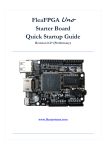
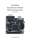
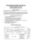
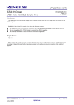
Flea86 level-1 System
User Manual
Revision 0.20 (Preliminary document)
Contents:
SECTION 1 - INTRODUCTION ............................................................................................................................ 3
SECTION 2 - GETTING STARTED WITH THE FLEA86 ............................................................................................. 4
SECTION 3 - USING THE FLEASET.EXE UTILITY .................................................................................................... 6
SECTION 4 - FLEA86 LEVEL-1 SYSTEM OVERVIEW .............................................................................................. 7
SECTION 5 - SOUND GENERATION .................................................................................................................. 12
SECTION 6 - VIDEO CONTROLLER .................................................................................................................... 13
SECTION 7 - FLEACOM SERIAL COMMUNICATIONS PORT ................................................................................. 20
SECTION 8 - FLEABUS-I CONTROL PORT .......................................................................................................... 24
SECTION 9 - MASS STORAGE .......................................................................................................................... 30
SECTION 10 – INPUT DEVICES ......................................................................................................................... 31
SECTION 11 - PC SYSTEM SERVICES ................................................................................................................. 33
APPENDIX A - HOW TO CREATE A CUSTOM DISK IMAGE .................................................................................. 35
APPENDIX B - CURRENT FLEA86 LEVEL-1 FIRMWARE STATUS........................................................................... 36
Flea86 level-1 User Manual
Date: 07/08/2012 Revision: 0.20 (Preliminary)
Page 2
Section 1 - Introduction
The aim of this manual is not only to inform the user of the capabilities of Flea86 (as well as its
limitations), but it also explores the simplicity (and potential power) associated with ‘tried-andtested’ variants of the mainstream DOS kernels i.e. MS-DOS, DR-DOS, FreeDOS etc.
Flea86 level-1 system is built around a small fast, modern 8052 microcontroller derivative
running a fully-custom emulator program (or virtual machine). All system functions (including
BIOS functions) are handled by the emulator, which is customizable to allow execution of a wide
range of PC software. It is recommended that all users become familiar with the FLEASET.EXE
utility as explained in section 3 of this manual.
For the electronics enthusiast, Flea86 allows for heaps of experimentation at a very low cost
with very simple and easy-to-use hardware. Users seeking to get the very most out of the
Flea86 (through programming and peripheral interfacing) are advised to read through the entire
manual. Users who are seeking to play a few old games from their personal collection or
freeware titles found online are encouraged to read Sections 3, 4 and Appendix ‘A’.
Attention all users! This manual is not a ‘how-to’ guide on using DOS of any variant. It is
essential that the user understands the basics of working under a DOS environment, or acquire
that understanding through the many resources available online.
Attention advanced users! It is assumed the advanced user possesses at least basic
knowledge and/or some experience in digital electronics application and circuit construction
techniques before attempting to build the example interface circuits outlined in this manual.
Flea86 level-1 User Manual
Date: 07/08/2012 Revision: 0.20 (Preliminary)
Page 3
Section 2 - Getting Started with the Flea86
Flea86 is designed as a ‘plug-and-play’ solution for a wide variety of applications. Following list
outlines the actual hardware and accessories needed to get up and running:
Flea86 level-1 system - What you will need:
1.) Flea86 level-1 main-board (of course!)
2.) +5V regulated DC power supply, with centre-pin positive DC plug
3.) VGA-compatible monitor or television capable of displaying 640x480 @ 60Hz refresh
rate or better
4.) PS/2-compatible keyboard (Flea86 will still boot without it connected)
5.) PS/2-compatible mouse (behavior same reason as point #4)
6.) Flea86 ‘startup disk’ MMC (or SD card with MMC-compatibility) flash card with one
bootable partition installed (User may also refer to Appendix A).
7.) Amplified audio speaker with a 3.5mm to 2.5mm phone jack adapter added
8.) This last item is merely optional and completely at the user’s discretion – a suitably wired
(off-the-shelf or custom) I/O daughterboard that plugs into the FleaBUS-I control port
Main-board system board layout:
VGA output
FleaBUS-I Header
Serial port
SD/MMC
interface
2.5mm audio
output jack
+5Vdc Power
supply input
PS/2
Keyboard
PS/2
Mouse
Flea86 System board pre-startup Precautions:
With over-current and reverse-polarity protection on it's input supply as well as current limiting
resistors on nearly all of it's board connectors, Flea86 hardware is reasonably well-protected
electrically. That said however, care should be exercised when powering up the bare
motherboard by:
1.) Ensuring there is nothing electrically conductive within close proximity to Flea86 system
board prior to power-up (including beverages i.e. coffee/beer etc.)
2.) Connection of all other peripherals to Flea86 and installation of the SD card prior to applying
input DC power.
Flea86 level-1 User Manual
Date: 07/08/2012 Revision: 0.20 (Preliminary)
Page 4
Section 2 - Getting Started with the Flea86 (Continued)
About the supplied ‘startup disk’:
On the MMC flash card (labeled ‘startup disk’) supplied with every Flea86 level-1, comes preinstalled with the following:
1.) Pre-formatted 502MB FAT32 partition
2.) Bootable FreeDOS kernel (currently version 2038)
3.) Cutemouse v1.9 mouse driver located in the root directory
4.) Flea86 example programs located in C:\F86DEMOS
5.) Flea86 example source code located in C:\F86DEMOS\SOURCE
Note: All Flea86 example programs require QuickBASIC interpreter to be installed on the flash
drive, which is freely available online.
Creating a custom Hard Disk image for the Flea86
Refer to Appendix ‘A’
Flea86 level-1 User Manual
Date: 07/08/2012 Revision: 0.20 (Preliminary)
Page 5
Section 3 - Using the FLEASET.EXE utility
Included with every Flea86 startup flash card is a small utility called FLEASET.EXE. This utility
program can be found in the \Flea86 folder of the flash card’s root directory, along with a copy of
the corresponding QuickBASIC source code.
Its purpose is to allow the user to configure various aspects of the Flea86 virtual machine to
enhance the overall system compatibility with both new and legacy software.
To run FLEASET.EXE, the user will type in the filename FLEASET at the DOS command
prompt (with the current directory pointing to the root directory) and press the ENTER key. The
user will then be presented with a configuration menu with five options - these are each
described in detail below:
Option #1.) Toggle virtual 8088 CPU speed (0=4.77MHz/1=7MHz)
Configures the Flea86 to allow a reasonable degree of compatibility, in terms of raw 8088 CPU
speed with selected (and also possibly very old!) legacy programs. Default is 7MHz on boot-up.
Option #2.) Disable virtual 8253 Timer #0 anti-alias filter (0=Enabled/1=Disabled)
When this parameter is set, Flea86 can accept faster/smaller 8253 timer reload values for
Timer#0 – which can be (sometimes) helpful for games that run the timer at a high reload-rate
(i.e. for speech-sample playback through the sound circuit). Anti-alias filter is enabled by default
on boot-up.
Option #3.) CPU overclock - WARNING: NOT RECOMMENDED!!! (90-140)
Configures the host CPU on the Flea86 to increase the emulated CPU speed/video refresh rate
should the user wish to run slightly more modern DOS software. Default is 90 (no over-clock).
Warning: this option increases the video refresh rate – make sure your video display
supports refresh rates above 60Hz otherwise damage may result, especially if it’s an
early-model CRT monitor! Recommended maximum overclock value to be 120.
Option #4.) Enable Hard Disk Write access
(0=Disabled/1=Enabled)
This option, if enabled, allows the MMC/SD card to be accessible to application programs for
writing as well as reading of hard disk sectors. Hard disk writes are disabled on boot-up.
Option #5.) Update Flea86 Emulator Firmware
Note: Make sure that you have the required binary (.BIN) image file in the same directory
as the FLEASET.EXE utility before selecting this option! Firmware updates are not
permanent and will only remain installed, so as long as power is applied to Flea86 and
that a hardware reset is not generated by the user.
When this option is selected, the FLEASET will then ask if you are sure about proceeding with
this option. Next it will ask for the filename (without the file extension) of the firmware update file
to be loaded into the Flea86 main processor. Once the filename is entered, FLEASET will
trigger a system warm boot of Flea86 and subsequently boot using the new firmware file.
Flea86 level-1 User Manual
Date: 07/08/2012 Revision: 0.20 (Preliminary)
Page 6
Section 4 - Flea86 level-1 system overview
The Flea86 level-1 virtual machine, like the system it was designed to emulate, consists of
many sub-systems that come together to form an IBM-PC. Following block diagram illustrates
how all these sub-systems and circuit modules come together.
Flea86 level-1 main-board system block diagram:
Serial
Port
(COM1)
CMOS
3.3V
RS-232
FleaCOM
UART
CRTC
DAC
VGA
Monitor
SN76496
+
Audio out
LPF
LPT DAC
+
PC speaker
8253
Timer
External devices:
Analog/Digital I/O
MMC/SD
Flash drive
8086
CPU
1MB System
RAM (including
video RAM)
FleaBUS-I
Peripheral
Control
Port
8259
PIC
HDD
Controller
8042
PS/2
PS/2 Keyboard
and mouse
1-MByte
RAM Disk
Flea86 level-1 User Manual
Date: 07/08/2012 Revision: 0.20 (Preliminary)
Page 7
Section 4 - Flea86 level-1 system overview (continued)
While the system block diagram on the previous page provides a simple overview, following
describes each sub-system block in more detail. Note: overall Flea86 compatibility with all
emulated components in the following list, are subject to the exceptions outlined in Appendix B.
8086 CPU:
Flea86 emulates an 8088 CPU with the following added opcodes as found in an 80188 CPU:
PUSHA, POPA, PUSH immediate
Flea86 executes at an equivalent 8086 CPU clock rate, which is adjustable, in the range of
3- 8MHz. This clock rate is adjustable and has an over-clock capability built into the Flea86
emulator. Both options are accessible via the FLEASET.EXE utility (refer section 3).
8253 System Timer:
In the Flea86 implementation of the 8253 Timer chip, Timers #0 and #2 are available.
8253 Timer #0: Programmable in the same manner as a real IBM-PC, subject to the exceptions
outlined in Appendix B. Timer #2 overflow interrupt is available at Interrupt vector 08h.
8253 Timer #2: Output is connected to the PC speaker and is controlled in a manner identical to
a real IBM-PC.
8259 Interrupt Controller:
Only the default ‘nested interrupt’ mode of the 8259 is supported in the Flea86 emulator. Refer
to the Port I/O map toward the end of this section for an overview of the related registers.
8042 PS/2 Keyboard and Mouse Interface Controller:
PS/2 keyboard services are handled by the FleaBIOS @ INT16h (refer to section 10), while the
‘keystroke detected’ hardware interrupt located at Interrupt vector 09h. Refer to the Port I/O map
toward the end of this section for an overview of the related registers.
PS/2 mouse services are handled by the FleaBIOS @ INT15h (refer to section 10). Mouse ‘activity
detected’ hardware interrupt is located at Interrupt vector 74h.
1 Megabyte RAM-Disk and Mass Storage Controller:
With the execution of the custom-supplied RAMDISK.COM, Flea86 provides a 1,018,368-byte
RAM Disk configured as Drive A:\
Flea86 provides basic MMC/SD flash card support for mass storage, accessible through the
FleaBIOS via the INT 13h handler (refer section 9). No user-accessible ports are available within
the I/O port map. Supported controller is simply a ‘generic’ device designed to provide basic
support. NOTE: Flea86 only supports flash cards that use 512-bytes per sector addressing i.e.
2GB SD cards will not work at all due to their 1024-byte sectors etc.
Flea86 level-1 User Manual
Date: 07/08/2012 Revision: 0.20 (Preliminary)
Page 8
Section 4 - Flea86 level-1 system overview (continued)
System RAM:
System RAM on the Flea86 main board consists of 640KByte conventional and up to 224Kbyte in
the upper memory region. Flea86 Memory Map is outlined in the following table:
Memory description:
Address range:
Interrupt Vector Table
0000h - 03FFh
BIOS/DOS/User Data Area
0400h - 05FFh
Standard user RAM area
0600h - 09FFFFh
MCGA/VGA Video RAM (64K max.)
0A0000h - 0AFFFFh
CGA/PCjr/TGA Video RAM (32K max.)
0B8000h - 0BFFFFh
Peripheral drivers / Upper Memory
0C8000h - 0EFFFFh
BIOS ROM / Upper Memory
0F0000h - 0FFFFFh
Video Controller:
Flea86 level-1 main board contains a virtual video controller with up to 128K VRAM, depending
on the selected video mode. Flea86 attempts to emulate the following graphics adapters:
CGA, PCjr/Tandy and MCGA. Refer to section 6 for specific details i.e. video service software
interrupt INT10h and Port I/O mapping details.
Audio Generator:
Flea86 consists of the following options for sound generation, which can be operated separately
or together if desired:
1.) SN76496 4-voice sound generator compatible
2.) User audio DAC channel available
3.) IBM-PC compatible PC speaker
Refer to section 5 for specific details relating to audio generation. Overall Flea86 compatibility with
this device is subject to the exceptions outlined in Appendix B.
Serial communication (via FleaCOM interface):
One RS-232 serial communications channel with 31-byte character receive buffer, supporting
the following speeds: 150, 300, 600, 1200, 2400, 4800, 9600 and 57600 Baud. Refer to
section 7 for specific details relating to the FleaCOM serial port.
Peripheral Expansion (via FleaBUS-I):
Enhanced SPI compatible port - up to sixteen external SPI-equipped slave devices can be
connected to the Flea86 for system I/O expansion. Refer to section 8 for specific details relating
to the FleaBUS-I control port.
Flea86 level-1 User Manual
Date: 07/08/2012 Revision: 0.20 (Preliminary)
Page 9
Section 4 - Flea86 level-1 system overview (continued)
System BIOS ROM (via FleaBIOS rev1.0a):
Flea86 contains its own built-in BIOS as an integral part of the Flea86 emulator. FleaBIOS
supports the following interrupt functions, details of which can be found in sections 6 and 9:
•
•
•
•
•
•
•
Int 10h AH = 00h, 02h, 03h, 05h, 06h, 07h, 08h, 09h, 0Ah, 0Bh, 0Eh, 0Fh, 10h, 11h, 12h, 1Ah, 1Bh
Int 11h, 12h
Int 13h AH = 00h, 02h, 03h, 08h, 15h
Int 15h AH = 88h, C0h, C2h
Int 16h AH = 00h, 01h
Int 19h
Int 1Ah AH = 00h, 01h
Overall FleaBIOS ROM compatibility is subject to the exceptions outlined in Appendix B.
Flea86 Main board Product Specifications:
Electrical:
Active current draw ~250mA @ 5V typical with no FleaBUS peripherals
installed and no over-clocking enabled.
Mechanical:
Overall dimensions 106 x 89mm overall. Four x 3.3mm mounting holes
with centers located at each corner of 94 x 80.4mm. System rated for
0-50deg.c temperature ambient with no CPU over-clocking enabled.
Flea86 level-1 User Manual
Date: 07/08/2012 Revision: 0.20 (Preliminary)
Page 10
Section 4 - Flea86 level-1 system overview (continued)
System I/O port map:
In addition to the BIOS ROM interrupt services, the Flea86 main board also provides direct
access to the on-board peripheral devices at the register level via port I/O mapping. Supported
system hardware registers are provided in the following table:
Port Address:
20-21h
40h
42h
43h
60h-62h
Port description:
8259 Programmable Interrupt Controller - interrupt service (20h) and mask (21h) registers
8253 Programmable Interval Timer - Timer#0 data load/store register
- Timer#2 data load/store register
- Configuration register
8042 PS/2 Input device controller
64h
C0-C1h
SN76496 Control registers (refer section 5)
3C8-3C9h
VGA Palette index/data registers (refer section 6)
3D4h-3D5h
6845 CRTC index/data registers (refer section 6)
3D8h
6845 CRTC hardware mode register (refer section 6)
3D9h
6845 CRTC CGA palette register (refer section 6)
3DAh
Video status register and Tandy Graphics palette index register (refer section 6)
3DEh
Tandy Graphics palette data register (refer section 6)
3DFh
Tandy Graphics page select register (refer section 6)
1000-1010h
FleaCOM serial communications port (refer section 7)
1011h
1200-1209h
Audio DAC output register (refer section 5)
FleaBUS-I control port (refer section 8)
FAAAh
Flea86 CONFIG – master enable register (write only)
Valid write values:
B7h = Flea86 hard disk writes to SD card are enabled.
FAABh
Flea86 CONFIG - Host CPU over-clock register (valid write values: 96h->B4h decimal)
FAACh
Flea86 CONFIG - Anti-alias control of the 8253 (1=ON and 0=OFF, normally ON)
FAADh
Flea86 CONFIG - v8088 clock select (valid write values: F5h = 4.77MHz, EEh = 8MHz)
FAAEh
Flea86 CONFIG - Start Flea86 firmware update cycle
Flea86 level-1 User Manual
Date: 07/08/2012 Revision: 0.20 (Preliminary)
Page 11
Section 5 - Sound generation
Flea86 level-1 sound generation capability is comprised of three separate circuits:
1. Basic tone (Beep) generation through the traditional PC-speaker sound generator
2. Musical note and noise generation is provided by an emulated clone of the SN76496 4voice sound chip, as used in classic systems ranging from the Tandy 1000 to the Sega
Master System game console.
3. Digitized sound playback, provided by a Flea86-specific 8-bit audio DAC. The DAC
output value can be updated by writing a data byte to I/O port #1011h. Note this port
feeds directly into the DAC channel and uses no DMA or data buffering.
Flea86 level-1 User Manual
Date: 07/08/2012 Revision: 0.20 (Preliminary)
Page 12
Section 6 - Video Controller
Flea86 level-1 supported Graphics Modes: The Flea86 video controller is built around two
main emulation modes, selectable via the disk signature set in the Master Boot Record of the
SD/MMC . These are
1.) CGA/TGA compatibility mode
2.) MCGA/VGA compatibility mode
Following table outlines the available video modes on the level-1 Flea86:
KB VRAM
Per page
BIOS ROM
INT10 Video
mode value
Comments
Partial
support only
Screen
Type
Colors
Emulation mode
# of
pages
40 x 25
text
16
both
1
2
00h, 01h
80 x 25
text
16
both
1
4
02h, 03h
160 x 100
Pixel
16
both
1
16
02h, 03h
160 x 200
Pixel
16
CGA/TGA only
1
16
06h
320 x 200
Pixel
4
both
1
16
04h
640 x 200
Pixel
2
both
1
16
06h
160 x 200
Pixel
16
CGA/TGA only
8
16
08h
320 x 200
Pixel
16
CGA/TGA only
4
32
09h
320 x 200
Pixel
256
MCGA/VGA only
1
64
13h
‘tweaked
text’ mode
‘Composite
TV’ mode
Up to 128K
VRAM
Available
Key:
CGA = Color Graphics Adapter
VGA = Video Graphics Array
Flea86 level-1 User Manual
TGA = Tandy Graphics Adapter
MCGA = Multi-Color Graphics Adapter
Date: 07/08/2012 Revision: 0.20 (Preliminary)
Page 13
Section 6 - Video Controller – BIOS INT10h Functions
Following table describes the INT10h services as supported by the Flea86 level-1 BIOS
(FleaBIOS rev 1.0a):
Sub-function
AH = nn
Function Description
00h
Sets video display mode,
clears video RAM and
loads default palette
01h
Text cursor control
02h
03h
Values Passed
to function
Values returned
from function
Comments
AL = video mode value
If bit 7 in AL is also set
before calling the function
the screen is not cleared
Video mode value
saved to BIOS data
area 0040:0049h
CH = cursor control, where:
40h = Cursor not visible
00h = Cursor visible
Video mode value
saved to BIOS data
area 0040:0049h
‘slow blink’ option
supported only for
visible cursor
Set text cursor position
DL = new cursor x
DH = new cursor y
None
Refer Appendix B
Get text cursor position
none
DL = cursor x
DH = cursor y
Get CPU page register
AL = 80h
BH = CRT page
BL = CPU page
Set CPU page register
AL = 81h
BL = CPU page
None
Set CRT page register
AL = 82h
BH = CRT page
None
Set both CRT and CPU
page registers
AL = 83h
BH = CRT page
BL = CPU page
None
05h
Flea86 level-1 User Manual
Date: 07/08/2012 Revision: 0.20 (Preliminary)
Page 14
Section 6 - Video Controller – BIOS INT10h Functions (continued)
Sub-function
AH = nn
Function Description
06h
Scroll text window
upwards
Values Passed
to function
Values returned
from function
AL = number of lines to scroll
(AL = 00h clears window)
BH = erase color
CH,CL = x, y of window
upper left corner
DH,DL = x, y of window
lower right corner
None
BH = 00h
AH = attribute
AL = character
07h
Scroll text window
downwards
08h
Read character and
attribute from current
cursor position
09h
Write character and
attribute to current cursor
position
AL = character
BH = 00h
BL = attribute
CX = number of times to
write char
None
0Ah
Write character only to
current cursor position
AL = character
BH = 00h
CX = number of times to
write char
None
0Bh
CGA Palette select
BH = 01h
BL = select palette
None
0Eh
Write character and
update cursor position
(teletype mode)
AL = new character
None
None
BH = 00h
AH = chars/ line
AL = current video
mode
0Fh
Get current video mode
Flea86 level-1 User Manual
Date: 07/08/2012 Revision: 0.20 (Preliminary)
Comments
Page 15
Section 6 - Video Controller – BIOS INT10h Functions (continued)
Sub-function
AH = nn
Function Description
Write Tandy color palette
- update single color only
Write Tandy color palette
- update entire table
10h
Write VGA color palette
DAC registers
Read VGA color palette
DAC registers
11h
Get EGA/VGA Font
status
Enable/Disable video
output
12h
1Ah
1Bh
Values Passed
to function
AL = 00h
BH = New color value
BL = Palette index
AL = 02h
ES:DX = far pointer to
source of new Tandy
palette color values
AL = 12h
BX = start palette index
CX = end palette index
ES:DX = far pointer to
source of new palette DAC
register values
(256 x 3 = 768 bytes total)
Valid data range per
color byte = 00h-0Fh
None
None
Location pointed
to by ES:DX
contains current
palette DAC
values
AL = 30h
ES = C000h
BP = 0500h
CX = 0008h
DL = 18h
BL = 10h
AL = video enabled, where:
00h = video enabled
01h = video disabled
BL = 36h
Get display combination
code
AL = 00h
Flea86 level-1 User Manual
Comments
None
AL = 17h
ES:DX = far pointer to read
palette DAC register values
(256 x 3 = 768 bytes total)
Get EGA hardware
information
Get VGA state
information block
Values
returned from
function
BX = 0000h
AL = 00h
ES:DI = far pointer to read
VGA adapter state table
(64 Bytes total)
BX = 0003h
CX = 0009h
BX = 0008h
AL = 1Ah
AL = 1Bh
Location pointed
to by ES:DX
contains current
VGA state table
data
Date: 07/08/2012 Revision: 0.20 (Preliminary)
Function only active
when VGA emulation
is selected in Flea86
configuration
Page 16
Section 6 - Video Controller – port I/O mapping
I/O Address 3C8h: VGA Palette index register
Port Read behavior:
Summary - NO FUNCTION
Port Write behavior:
Summary - VGA Palette DAC register select
Details Selects the desired VGA palette DAC register to modify.
Valid data range 00h->FFh.
I/O Address 3C9h: VGA Palette data register
General behavior:
Note: three successive reads (or writes) must be made to this register after setting 3C8h, with the
lower six-bits of a byte read out corresponding to a primary color (red, then green and lastly blue).
This is because the VGA palette registers are 18-bits wide configured as 6-bits per Red, Green and
Blue analog video.
Also note that the Flea86 truncates the DAC value to 3/3/2 bits per R/G/B to simplify output circuitry.
Valid data range is 00h->3Fh.
Port Read behavior:
Summary - Reads from specified VGA Palette DAC register
Details Retrieves the addressed color palette register value pointed to by port 3C8h. Note
that three successive reads from this register are required to retrieve one DAC value (see above).
Port Write behavior:
Summary - Writes to specified VGA Palette DAC register
Details Updates the addressed color palette register value pointed to by port 3C8h. Note that
three successive writes to this register are required to update one DAC value (see above).
I/O Address 3D4h: 6845 CRTC index register
Port Read behavior:
Summary - NO FUNCTION
Port Write behavior:
Summary - 6845 CRTC register select
Details Selects the desired register index for the 6845 CRTC register block
Note - only register index #9 supported, therefore the only valid value here is 9!
Flea86 level-1 User Manual
Date: 07/08/2012 Revision: 0.20 (Preliminary)
Page 17
Section 6 - Video Controller – port I/O mapping (continued)
I/O Address 3D5h 6845 CRTC register data transfer
Port Read behavior:
Summary - 6845 CRTC register read
Details Retrieves the addressed 6845 CRTC register value pointed to by port 3D4h
Port Write behavior:
Summary - 6845 CRTC register write
If CRTC index was setup to point to register 9, this sets up the ‘number of scan
Details lines per character’. Used for generating the 160x100 ‘tweaked text’ mode, by setting index
register 9 with the value of 2 while in 80x25 text mode.
Valid data range for CRTC index #9 is 0->7h
I/O Address 3D8h 6845 CRTC hardware mode
Port Read behavior:
Summary - NO FUNCTION
Port Write behavior:
Bit 0 = ’80_column_textmode’ When bit set to 1, tells the CRTC to generate to 80-columns
text (only works in text mode), otherwise 40-columns is selected. Default is ON (1).
Bit 1 = ‘medium_resolution_mode’ When bit set to 0, selects character text display mode,
else 320x200 graphics mode is selected. Default is OFF (0)
Bit 2 = ‘colorburst_disable’ When bit set to 1, turns off the composite TV color burst signal.
Activates the 160x200 CGA composite-color mode when the 640x200 monochrome graphics
mode is set. Default is ON (1).
Bit 4 = ‘high_resoultion_mode’ When bit set to 1, Selects 640x200 monochrome video mode.
Default is OFF (0)
All other bit settings in this port are not used
I/O Address 3D9h 6845 CRTC palette select
Port Read behavior:
Summary - NO FUNCTION
Port Write behavior:
Note: the following only works in conjunction with CGA 320x200-4 color mode!
Bit 4 = ‘palette_high_intensity’ When bit set to 1, the intensity of the currently selected CGA
palette is increased in accordance with the legacy CGA specification.
Bit 5 = ‘palette_mode’ When bit set to 1, selects the alternate CGA 4-color palette in
accordance with the legacy CGA specification.
All other bit settings in this port are not used
Flea86 level-1 User Manual
Date: 07/08/2012 Revision: 0.20 (Preliminary)
Page 18
Section 6 - Video Controller – port I/O mapping (continued)
I/O Address 3DAh 6845 CRTC video status / Tandy Graphics Palette index
Port Read behavior:
Bit 0 = ‘video retrace active’ When bit set to 1, indicates when either horizontal or vertical
retrace are in progress.
Bit 3 = ‘vertical retrace active’ When bit set to 1, indicates when only the vertical retrace is in
progress.
Port Write behavior:
Summary - TGA Palette DAC register select
Details Selects the desired Tandy Graphics palette color to modify.
Valid data range 10h->1Fh.
I/O Address 3DEh Tandy Graphics Palette data
Port Read behavior:
Summary - NO FUNCTION
Port Write behavior:
Summary - TGA Palette DAC indirect color write
Modifies the color palette register pointed to by port 3DAh with a standard ‘Tandy
Details ROM’ color passed by a valid value written to this port.
Valid data range 0h->0Fh
I/O Address 3DFh Tandy Graphics Video Page Register
Port Read behavior:
Summary - NO FUNCTION
Port Write behavior:
Bits 0-2 = ‘CRT 16K video pager select’ Selects one of eight video pages to be accessed by
the CPU @ B000:8000h. For the 320x200 16-color mode, least significant bit is ignored.
Bits 5-3 = ‘CPU 16K video pager select’ Selects one of eight video pages to be accessed by
the CRTC @ B000:8000h. For the 320x200 16-color mode, least significant bit is ignored.
All other bit settings in this port are not used
I/O Address 1010h Flea86 Video Output Control
Port Read behavior:
Bit 0 = ‘video enabled’ When enabled, allows data from VRAM to be sent to the video RGB
outputs at the appropriate time. When disabled, the RGB outputs are switched off, though V/HSync signals are still active. Normally ON (1)
All other bit settings in this port are not used
Port Write behavior:
Summary - NO FUNCTION
Flea86 level-1 User Manual
Date: 07/08/2012 Revision: 0.20 (Preliminary)
Page 19
Section 7 - FleaCOM serial communications port
Note: Users seeking a PC-compatible serial port solution for Flea86 are recommended to
look at either building or purchasing an ISA-bus expansion option for Flea86.
For serial communication on the Flea86 level-1, a very simple solution is implemented. While
this is opposed to any genuine (read complex and/or cumbersome) PC serial COM solution, it
does allow an effective means of serial communication that is very straightforward to program regardless of programming language used!
Essentially, the FleaCOM serial port is built around a small handful of I/O port registers that
implement the following three functions:
1.) Baud-rate initialization
2.) Transmit buffer of one-byte in length, with status provided by a ‘transmit status’ flag bit
3.) Receive buffer of 31-bytes in length, with status provided by a ‘received character
counter’
FleaCOM serial port – Electrical details
Two options exist currently for connecting Flea86 to external devices via the on-board serial
channel
1.) To a remote PC via USB virtual COM port (note: Prolific PL2303HX device driver
required if using MS Windows XP/Vista/7. No device driver is required for Linux kernel
builds 2.6.8 onwards).
2.) Via 3.3V logic interface directly to the host micro’s UART using the on-board 4-way
header (Warning: ‘SJ2’ solderable junction MUST BE CUT prior to using this option!!)
‘SJ2’ Must be cut
(isolated) before using
the 4-way header option
UART header
1) GND
2.) RXD pin
3.) TXD pin
4.) +3.3V
FleaCOM serial port – BIOS interrupt functions
None available - FleaCOM access must be performed through port I/O only. Please refer to the
specific port I/O mapping on the following page.
Flea86 level-1 User Manual
Date: 07/08/2012 Revision: 0.20 (Preliminary)
Page 20
Section 7 - FleaCOM serial port – port I/O mapping
I/O Address 1000h FleaCOM configuration and transmit status register
Port Read behavior:
Bit 0 = ‘transmitter_status’ When bit set to 1, tells the user that one byte was transmitted from
the transmit buffer, otherwise a byte transmit is underway and the transmitter is busy. User must
test this bit first to ensure reliable transmission of data from the Flea86. Default is OFF (0).
All other bit settings in this port are not used
Port Write behavior:
Summary - FleaCOM Set low speed baud rate
Details When a value ranging between 0->6 is sent to this register, the FleaCOM port
baud-rate generator is configured for one of seven pre-set baud-rates. Valid values and their
corresponding baud-rates are: 0 (9600 Baud), 1 (4800 Baud), 2 (2400 Baud), 3 (1200 Baud),
4 (600 Baud), 5 (300 Baud), 6 (150 Baud)
I/O Address 1001h FleaCOM Transmit / Receive register
Port Read behavior:
Summary - Read in a received byte from the serial port
When this register is read, a byte (if available) is passed from the receive buffer
Details and the buffer count is decremented by one. Before accessing this register, the user must first
check to see if any bytes were received and waiting in the receive buffer by checking for a nonzero value in the buffer count register (I/O Address 1002h)
Port Write behavior:
Summary - Sends a byte to the serial port transmitter
Details When data is written to this register, this data is passed on to the serial
transmitter and (assuming it is not busy!) serial transmission of the byte will commence. Note:
before accessing this register, the user must first check to see if the last serial transmission was
successful by checking for a non-zero value in the transmit status register (I/O Address 1000h)
I/O Address 1002h FleaCOM receive buffer counter
Port Read behavior:
Summary - Read current receive buffer count
Details Current receive buffer count is obtained by reading from this register. Valid
values range from 0h->1Fh, with 1Fh indicating buffer overflow condition (requiring the count
value to be reset by the user – see immediately below)
Port Write behavior:
Summary - Set current receive buffer count
Details When data is written to this register, the data buffer count is updated to the new
value. Nominal write value in most cases is ‘0’ for initialization or buffer overflow purposes only.
Flea86 level-1 User Manual
Date: 07/08/2012 Revision: 0.20 (Preliminary)
Page 21
Section 7 - FleaCOM serial port – port I/O mapping (continued)
I/O Address 1003h FleaCOM High baud-rate enable
Port Read behavior:
Summary - NO FUNCTION
Port Write behavior:
Summary - Selects between standard and high baud-rate operation
When data is written to this register, this data is passed on to the serial
Details transmitter and (assuming it is not already busy) serial transmission of the passed byte will
commence. Note: before accessing this register, the user must first check to see if the last serial
transmission was successful by checking for a non-zero value in the transmit status register (I/O
Address 1000h)
I/O Address 1004h FleaCOM High baud-rate select
Port Read behavior:
Summary - NO FUNCTION
Port Write behavior:
Summary - Select between 57,600 Baud or 115200 Baud (or ‘other..’)
When valid data is written to this register, the FleaCOM port baud-rate generator
Details is configured for one of two high baud-rates. User must have the High baud-rate mode enabled
as well before the following baud rates are configured. Valid values and their corresponding
baud-rates are: 0A3h = (57,600 Baud), 51h = (115,200 Baud)
Attention: All high-speed baud-rates given here are close approximations, not exact values
(actual values are; 57,515 and 115,740 Baud respectively). High-speed baud-rates are also
sensitive to over-clocking, due to the use of the (adjustable) 100MHz internal system clock
instead of the external crystal as the baud-rate clock source.
Flea86 level-1 User Manual
Date: 07/08/2012 Revision: 0.20 (Preliminary)
Page 22
Section 7 - FleaCOM serial port – programming example
The following code example provides a good demonstration of the Flea86 serial port in action.
Note: while a copy of this program already resides on the ‘startup disk’, you may copy/paste the
following text on this page and save it as a .BAS file in a text editor if required.
Simple Flea86 Serial terminal Program. Written for the
' Microsoft QuickBasic Interpreter 1.1 by Valentin Angelovski (c) 2011
'
' To use the program, you will need a null modem cable and
' connect to a remote terminal using the following comms settings:
' 9600 baud 8,N,1 with NO handshaking enabled! That's it.. :-)
'
' NOTES:
' * Only non-extended keys are processed for tranmission in this simple program!
' * While possible, this simple program does not check for receive buffer overrun!
' Set Flea86 baudrate to 9600. Can be changed from 300-9600 baud, valid values are:
' 0 = 9600 Baud 1 = 4800 Baud 2 = 2400 Baud 3 = 1200 Baud 4 = 600 Baud 5 = 300 Baud
OUT &H1000, 0
' Clear receive buffer 'bytes received' count
OUT &H1002, 0
' Transmit null character to initialise transmitter
OUT &H1001, 0
' Clear screen and display welcome message
CLS
PRINT " Flea86 simple 9600 N81 serial terminal! Press ESC to exit "
' Begin Terminal main loop
main:
' Get receive buffer count and if non-zero then read in a buffered character and display it..
IF (INP(&H1002) > 0) THEN PRINT CHR$(INP(&H1001));
' Check for local user keystroke
a$ = INKEY$
' If no user keystroke detected, go back and repeat
IF (LEN(a$) = 0) THEN GOTO main
IF a$ = CHR$(27) THEN END
' Local user keystroke detected!
' Is the transmitter busy? If no, get local keystroke and transmit it, else wait for previous
' keystroke transmission to complete
TransmitterBusy:
IF (INP(&H1000) > 0) THEN usrkey% = ASC(a$): OUT &H1001, usrkey%: a$ = "": GOTO main
GOTO TransmitterBus
Flea86 level-1 User Manual
Date: 07/08/2012 Revision: 0.20 (Preliminary)
Page 23
Section 8 - FleaBUS-I control port
In terms of system expansion on the Flea86 level-1, a simple yet flexible control port has been
made available for this purpose.
Update: An optional ISA bus breakout option with limited I/O capability is now also
available for Flea86, please refer to specific technical info regarding the item
The FleaBUS-I is essentially an SPI-master interface, with three slave address lines and an
additional programmable output pin. This allows the connection, of either up to eight (using one
74HC138 decoder) or sixteen (using two 74HC138 decoders, with each decoder ‘bank’
addressed using the ‘programmable output’ pin) SPI-capable slave devices respectively.
Transfer rate from this port is fixed at 5 Megabits/sec peak transfer rates. FleaBUS is equipped
with a six-byte packet buffer, enabling easy data transfer of multi-byte commands and
responses between the FleaBUS-I and connected SPI peripheral slaves. FleaBUS-I can be
configured to receive data responses in the form of either byte or word form.
FleaBUS-I does have several limitations:
1.) Only SPI TIMING MODE 0 (i.e. CPOL=0 / CPHA=0) is supported at this time
2.) All response packets to the FleaBUS-I from any slave can only return one byte or one word.
3.) Data streaming to any SPI peripheral is not supported
FleaBUS-I control port – Electrical details:
Pin 13
Pin 11
Pin 9
Pin 7
Pin 5
Pin 3
Pin 1
IRQ7
SA1
SA0
GND
/RESET
IRQ3
+3.3V
Pin 14
Pin 12
Pin 10
Pin 8
Pin 6
Pin 4
Pin 2
FBUS/USR
SELECT
SA2
MCLK
MOSI
MISO
/CS
Pin(s):
Pin name(s):
I/O type:
Pin description:
1
2
3
4
5
6
7
8
9, 11, 10
12
13
14
+3.3V
/CS
/IRQ7
MISO
/RESET
MOSI
GND
MCLK
SA0, SA1, SA2
FBUS/USR SEL
/IRQ3
NC
Supply
output
input
input
output
output
Ground
output
output
output
input
none
Peripheral supply (300mA maximum)
Slave chip select (active low)
External Interrupt Request line #3
Master-in data pin (SPI Mode 0)
System reset (active low)
Master-out data pin (SPI Mode 0)
System ground
Master Clock (SPI Mode 0)
SPI slave address lines (3 address lines to be decoded)
FleaBUS ISA breakout or SPI user bus select pin
External Interrupt Request line #7
Reserved (do not connect)
Flea86 level-1 User Manual
Date: 07/08/2012 Revision: 0.20 (Preliminary)
Page 24
Section 8 - FleaBUS-I Control port – Port I/O mapping
I/O Address 1200-1207h: Initiate data transfer to specific SPI slave
General behavior:
During either a read or write cycle, slave address lines SA0, SA1 and SA2 output states will mirror the
least 3-bits of the addressed I/O Port i.e. 1200-1207h = 000 ->111 for Slave Address (SA) bits 2,1 and 0.
In the case of multi-byte transfers, data is first shifted out of the ‘packet build buffer’ with the first byte
corresponding to the first byte loaded into the buffer load register (1208h), then the subsequent read (or
write) instruction is processed at the trailing end of the sent/received data packet.
Port Read behavior:
Summary - Reads response packet of specific SPI slave
Read single (or the lower byte of a word) byte from a specific SPI slave into 8086
Details CPU ‘AL’ register or a combination of ‘AL’ contents and the ‘Packet build buffer’ (if loaded).
The upper byte for SPI word data reception is available @ I/O port 1208h.
Port Write behavior:
Summary - Sends command/data packet to specific SPI slave
Details Send single byte (or up to 7-byte) packet to a specific SPI slave out from either the 8086 CPU
‘AL’ register or a combination of ‘AL’ contents and the ‘Packet build buffer’ (if loaded).
I/O Address 1208h: FleaBUS-I SPI extended mode transfers
Port Read behavior:
Summary - Read received MSByte register (word reception mode only)
Details Returns the upper byte of the last data word response received over the SPI into the 8086
CPU ‘AL’ register, provided that ‘word_receive_enable’ bit is set as described in port 1209h below. Valid data
only becomes available in this register, once a read to any one of I/O ports 1200-1207h has taken place first –
and this sequence must be carried out for every data word read cycle.
Port Write behavior:
Summary - Load ‘Packet build buffer’ register
Details Loads a single byte into the packet build buffer from the 8086 CPU ‘AL’ register, with the
buffer character count incremented by one. The packet build buffer is basically a first-in-first-out (FIFO)
type of six bytes in length. Packet buffer must also be reloaded for all multi-byte transfers, since the
packet count is reset to zero during any subsequent access to ports 1200-1207h
I/O Address 1209h: FleaBUS-I configuration register (write-only)
Port Write behavior:
Bit 0 = ‘word_receive_enable’
When set, Puts FleaBUS-I into data word read mode. Normally OFF (0)
Flea86 level-1 User Manual
Date: 07/08/2012 Revision: 0.20 (Preliminary)
Page 25
Section 8 - FleaBUS-I interfacing examples
Generating single-byte data transfers: Suppose one wanted to read data from a single-channel
8-bit analog-to-digital converter (i.e. TLC548) or control the state of an 8-bit serial-to-parallel
output device (i.e. 74HC595). Following examples will produce their respective logic waveforms
as illustrated below (Note: ‘word_receive_enable’ bit is assumed to be in default state i.e. OFF)
Example 1: Write output byte 83hex to 74HC595 (slave address #03):
Example schematic (Note: IC supply/ground pin connections not shown):
Coding example for the above circuit, in the following languages:
Intel 8086 Assembly
Microsoft QuickBasic
MOV AL,83h
MOV DX,1203h
OUT DX,AL
OUT &H1203, &H83
Borland C
outp(0x1203, 0x83);
Resultant waveform:
MCLK
MOSI
1
0
0
0
0
0
1
1
/CS
SA0
SA1
SA2
Flea86 level-1 User Manual
Date: 07/08/2012 Revision: 0.20 (Preliminary)
Page 26
Section 8 - FleaBUS-I interfacing examples (continued)
Example 2: Read analog data byte from TLC548 (slave address #07):
Example Schematic (Note: 74HC138 supply/ground pin connections not shown):
Coding example for the above circuit, in the following languages:
Intel 8086 Assembly
Microsoft QuickBasic
Borland C
MOV DX,1207h
IN
AL,DX
inbyte = INP(&H1207)
inbyte = inp(0x1207);
Resultant waveform:
MCLK
MISO
/CS
SA0
SA1
SA2
Flea86 level-1 User Manual
Date: 07/08/2012 Revision: 0.20 (Preliminary)
Page 27
Section 8 - FleaBUS-I interfacing examples (continued)
Generating multiple-byte data transfers: Now that we have looked at interfacing to simple SPIcapable devices, let’s move onto something a little more complicated. Suppose we want to
control or monitor a more sophisticated device, such as an MCP23S09 programmable I/O chip,
containing around 12 (addressable) registers internally and requires all data transfers (i.e.
master command and slave response) on the bus to be exactly 3-bytes in length. Typical
MCP23S09 data packet begins with a command byte, followed by an internal register address
byte and finally a data-byte transfer (i.e. byte read or write) as directed by the command byte.
Note that only the most basic mode of operation is utilized in the MCP23S09 for the following
example – users are encouraged to study the specific MCP23S09 product data sheet for
information about other possibilities available with this device.
Example 3: Read port A status from MCP23S09 (slave address #05):
Example Schematic (Note: 74HC138 supply/ground pin connections not shown):
Coding example for the above circuit, in the following languages:
Intel 8086 Assembly
Microsoft QuickBasic
Borland C
MOV
MOV
OUT
MOV
OUT
MOV
IN
OUT &H1208, &H41
OUT &H1208, &H9
inbyte = INP(&H1205)
outp(0x1208,0x41); // Load command bytes
outp(0x1208,0x09); // into packet buffer
inbyte = inp(0x1205); // Send 2bytes and read
DX, 1208h
AL, 41h
DX, AL
AL, 9h
DX, AL
DX, 1208h
AL, DX
Flea86 level-1 User Manual
rd
in the 3 byte response
Date: 07/08/2012 Revision: 0.20 (Preliminary)
Page 28
Section 8 - FleaBUS-I interfacing examples (continued)
Resultant waveform from sending a ‘Port-A read’ 3-byte packet:
MCLK
MOSI
‘Slave read’ command
MISO
‘Port A address’ command
‘Port A’ value from MCP23S09
/CS
SA0
SA1
SA2
Flea86 level-1 User Manual
Date: 07/08/2012 Revision: 0.20 (Preliminary)
Page 29
Section 9 - Mass Storage
Mass Storage BIOS interrupt functions:
Following table describes the INT13h services as supported by the Flea86 level-1 BIOS
(FleaBIOS rev 1.0a):
Sub-function
AH = nn
Function Description
00h
Reset mass storage
controller
01h
02h
03h
08h
Drive controller status
Read sector(s) from
drive
Write sector(s) to
drive
Values Passed
to function
DL = drive number
AH = error code,
where 00h = no error
If function failure,
CPU carry flag = 1
DL = drive number
AH = error code,
where 00h = no error
If function failure,
CPU carry flag = 1
AL = number of sectors to
read/write (must be nonzero)
CH = low eight bits of
cylinder
CL = sector number 1-63
(bits 0-5) and high two bits of
cylinder (bits 6-7)
DH = head number
DL = drive number
ES:BX = pointer to source
(or destination) buffer in
memory
Get drive parameters
Values returned
from function
DL = drive number
Comments
AH = error code,
where 00h = no error
AL = number of
sectors transferred
If drive read function
successful, address
pointed to by ES:BX
should contain
transferred data
If function failure,
CPU carry flag = 1
FleaBIOS rev 1.0a
only supports drive
number = 80h
(fixed disk)
Refer Appendix B
AH = 00h
BL = 00h
CX = FDFFh
DX = 0F01h
If function failure,
CPU carry flag = 1
CX = 000Fh
DX = B430h
15h
Get drive type
Flea86 level-1 User Manual
DL = drive number
If function failure,
AH = 00h, otherwise
AH = 03h
Date: 07/08/2012 Revision: 0.20 (Preliminary)
Page 30
Section 10 – Input Devices
PS/2 Mouse BIOS interrupt functions:
Following table describes the INT15h services as supported by the Flea86 level-1 BIOS
(FleaBIOS rev 1.0a):
Sub-function
AH = nn
Function Description
88h
Get installed RAM
capacity above 1MByte
C0h
Get system configuration
bytes from ROM table
None
Values returned
from function
Comments
AX = 0000h
ES = F000h
BX = E6F5h
None
AH = 00h, as it is a
supported function
AL = 00h
BH = PS/2 mouse control,
where PS/2 Mouse Active
BH = 1, (BH = 0 to turn off)
None
Get mouse ID
AL = 01h
BX = 00AAh
Reset mouse
AL = 05h
None
Mouse interface control
C2h
Values Passed
to function
AL = 07h
Set Custom handler
address
‘Other’
Unsupported function
Flea86 level-1 User Manual
ES:BX = pointer to custom
mouse handler, normally
used by a resident mouse
driver
None
None
AH = 86h
CPU carry flag = 1
Date: 07/08/2012 Revision: 0.20 (Preliminary)
Page 31
Section 10 - Input Devices (continued)
PS/2 Keyboard BIOS interrupt functions (continued):
Following table describes the INT16h services as supported by the Flea86 level-1 BIOS
(FleaBIOS rev 1.0a):
Sub-function
AH = nn
Function Description
00h
Get (or wait) for key
press
Values Passed
to function
None
Values returned from
function
Comments
AH = BIOS scan code
AL = ASCII character
AH = BIOS scan code
AL = ASCII character
01h
Get keyboard status
None
If key-press detected, CPU zero
flag = 0 else
CPU zero flag = 1
AL = Extended key bitmask,
where:
02h
Get extended status
None
Bit 7 = Insert active
Bit 6 = CapsLock active
Bit 5 = NumLock active
Bit 4 = ScrollLock active
Bit 3 = Alt key pressed
Bit 2 = Ctrl key pressed
Bit 1 = left shift key pressed
Bit 0 = right shift key pressed
Note: this byte is also duplicated
in the BIOS data area @
0040:0017h
Flea86 level-1 User Manual
Date: 07/08/2012 Revision: 0.20 (Preliminary)
Page 32
Section 11 - PC system services
Main board BIOS interrupt functions:
Following table describes the INT11h services as supported by the Flea86 level-1 BIOS
(FleaBIOS rev 1.0a):
Sub-function
AH = nn
Not needed
Function Description
System Hardware
configuration
Values Passed
to function
Values returned
from function
AX = Hardware
configuration word
None
Comments
In Flea86, this
function returns with
AX = 4304h when
TGA/PCjr mode is
set. Otherwise
function returns
AX = 4324h
Following table describes the INT12h services as supported by the Flea86 level-1 BIOS
(FleaBIOS rev 1.0a):
Sub-function
AH = nn
Function Description
Not needed
System memory
configuration
Values Passed
to function
Values returned from
function
AX = installed
conventional RAM in
kilobytes
None
Comments
RAM capacity
retrieved from
BIOS data area
0040:0049h
Following table describes the INT15h services as supported by the Flea86 level-1 BIOS
(FleaBIOS rev 1.0a):
Sub-function
AH = nn
Function Description
88h
Get installed RAM
capacity above 1MByte
C0h
Get system configuration
bytes from ROM table
Flea86 level-1 User Manual
Values Passed
to function
None
Values returned
from function
Comments
AX = 0000h
ES = F000h
BX = E6F5h
None
AH = 00h, as it is a
supported function
Date: 07/08/2012 Revision: 0.20 (Preliminary)
Page 33
Section 11 - PC system services (continued)
Main board BIOS interrupt functions (continued):
Following table describes the INT19h services as supported by the Flea86 level-1 BIOS
(FleaBIOS rev 1.0a):
Sub-function
AH = nn
Function Description
Don’t care
Initiate warm reset
Values Passed
to function
None
Values returned
from function
None
Comments
Reboots Flea86
Following table describes the INT1Ah services as supported by the Flea86 level-1 BIOS
(FleaBIOS rev 1.0a):
Sub-function
AH = nn
00h
01h
Function
Description
Get system
Time
Set system
Time
Flea86 level-1 User Manual
Values Passed
to function
Values returned from
function
DX = current least significant
word of 32-bit ‘tick’ count
CX = current most significant
word of 32-bit ‘tick’ count
None
DX = New least significant
word of 32-bit ‘tick’ count
CX = New most significant
word of 32-bit ‘tick’ count
None
Date: 07/08/2012 Revision: 0.20 (Preliminary)
Comments
System ‘tick’ timer normally
counts at a rate of
(approximately) 18.2 ‘ticks’
per second.
Note: Timer value is also
stored in the BIOS data
area. ‘Tick’ timer count is
stored in four successive
bytes starting @
0040:0017h in little-endian
format
Page 34
Appendix A - How to create a custom disk image
THIS SECTION IS UNDER CONSTRUCTION
Flea86 level-1 User Manual
Date: 07/08/2012 Revision: 0.20 (Preliminary)
Page 35
Appendix B - current flea86 level-1 firmware status
(Current from 13th June 2011)
Hardware emulation:
•
8088 CPU module
o
•
6845 graphics module
o
o
o
•
99.8% Functional with some 80186-level instruction support added
Limited 6845 support at the register level – hardware scrolling not supported.
40-column text modes only partially supported.
Maximum scan-lines displayed on-screen is 200 in all available modes
8253 timer module
o
o
o
o
o
o
Timer modes 2 & 3 are supported only.
Timer channel 0 registers have limited read-back capability.
Timer channel 1 (DRAM refresh timer) is unavailable.
Timer channel 2 is dedicated to the speaker operation only.
Maximum timer resolution limited to ~10-bits (Timer 0)
High-rate timer interrupt setups (>2KHz) are not recommended due to high overhead
•
8237 DMA module
•
8259 interrupt module
•
8042 keyboard module
•
UART module
o
o
o
o
•
Basic functionality provided - limitations exist with some extended key modes
FleaCOM serial port, while greatly simplified over a genuine PC COM port, is not
compatible to a standard PC COM port at the register level.
All mass-storage data transfers are handled directly via BIOS int 13h.
Emulator can only mount the flash disk upon system boot-up.
Only MMC part of mass-storage interface thoroughly tested.
BIOS support for one partition on the disk only.
SN76496 Sound Generator
o
•
Only basic (PC default) functionality provided i.e. nested interrupt priorities etc.
Mass storage module
o
o
o
o
•
Not implemented, can be bypassed in most cases.
Functional, though with a linear volume control on all channels and using a different noise
generation source
FleaBUS-I Control Port
o
Functional. Cannot process uninterrupted data streams due to sharing of the MCLK
signal with both the MMC and SDRAM input clock.
BIOS function map:
•
Int 10h functions
o
o
•
Cursor display options limited to ‘blinking’ or ‘off’
Several very minor bugs remain
Int 13h functions
o
o
Only CHS mapping supported, meaning 502MB disk space maximum under MS-DOS.
Drive controller currently supports only one drive located at 80h (C>)
•
Int 14h functions
•
Int 15h functions
•
Int 16h functions
•
Int 1Ah functions
o
o
o
o
Not supported. FleaCOM serial port uses Flea86 custom I/O port mapping only.
Implemented
Limitations exist in certain extended key combinations in function AH=02h
Real time clock related functions omitted from basic Flea86 level-1 specification
Flea86 level-1 User Manual
Date: 07/08/2012 Revision: 0.20 (Preliminary)
Page 36
Notes on PC Compatibility:
Due to firmware constraints within the host MCU, this document is intended to serve as a basic
guide for ‘minimum system’ requirements with respect to CPU, BIOS and peripheral
functionality. Apart from the features outlined in this specification, no other claims are made
regarding compatibility with an IBM-PC or equivalent system.
Product Warranty and Liability:
This document is preliminary and stated product or solution on offer is currently not yet
available. Warranty terms will be provided closer to the release date. Liability shall be limited to
replacement of the Flea86 system box due to a problem (proven to) stem from manufacturing
and/or design fault only.
Legal Notice:
The Flea86 is NOT to be used as a solution for applications deemed to be
Safety-critical or life-support related. The user shall assume all responsibility for any
consequences arising from such use.
While every effort is made to ensure the information presented is accurate I, Valentin
Angelovski, make no such guarantee. I also reserve the right to update this product specification
sheet without prior notice. Flea86 level-1 emulation software and ‘mascot’ logo is the copyright
of Valentin Angelovski. All trademarked product names listed herein belong to their respective
trademark owners.
Copyright © 2009-2012 Valentin Angelovski
Flea86 level-1 User Manual
Date: 07/08/2012 Revision: 0.20 (Preliminary)
Page 37