1
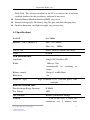
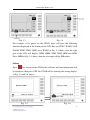
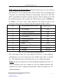
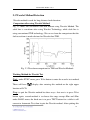
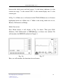
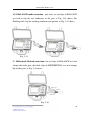
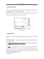
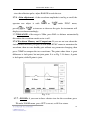
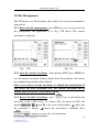
ST880 Cable Fault Locator
User Manual
=======================================
ST880 Cable Fault Locator
All rights reserved. No part of this manual shall be reproduced, stored in a retrieval
system, or transmitted by any means, electronic, mechanical, photo-copying,
recording, or otherwise, without written permission from Shandong Senter
Electronic Co. Ltd. Although every precaution has been taken in the preparation of
this manual, Shandong Senter Electronic Co. Ltd. assumes no responsibility for
errors or omissions. Neither is any liability assumed for damages resulting from the
use of the information contained herein.
Declaration:
SENTER reserves the right to change specifications or designs described herein
without any notice or obligations.
1
ST880 Cable Fault Locator
CONTENT
Chapter1 General..............................................................................................................0
1.1 General information ..............................................................................................0
1.2 Features .................................................................................................................0
1.3 Specifications ........................................................................................................1
1.4 ST880 Layout and Appearance .............................................................................3
1.5 Operation...............................................................................................................4
1.6 The Procedures for Detection................................................................................7
Chapter 2 Pulse Reflection (TDR) Detection ................................................................10
2.1 Working Principle................................................................................................10
2.2 Concepts..............................................................................................................11
2.3 Wavelet Method Detection ..................................................................................14
2.4 TDR method........................................................................................................15
2.5 Connection ..........................................................................................................19
2.6 Automatic Test.....................................................................................................21
2.7 Manual Test .........................................................................................................21
2.8 Measurement of VOP and Calibration ................................................................23
2.9 File Management.................................................................................................24
Chapter 3 Bridge Method...............................................................................................26
3.1 Working Principle................................................................................................26
3.2 Bridge test interface introduction ........................................................................27
3.3 Multimeter function.............................................................................................28
3.4 Connection Method for Bridge method...............................................................29
3.5 Bridge Method Test Procedure............................................................................31
3.6 Input the total length, to calculate the fault distance ...........................................32
Chapter 4 Data Analysis Software ....................................................................................35
Chapter 5 Power..............................................................................................................35
2
ST880 Cable Fault Locator
Chapter 6 Troubleshooting.............................................................................................35
3
Chapter1 General
1.1 General information
ST880 =TDR + Bridge
ST880=Automatic Detection + Manual Detection
ST880 Cable Fault Locator is the latest test instrument developed by Senter
Corporation, its working principle is Time Domain Reflectometer (TDR)
and Bridge Methods. It is a very convenient, intelligent and reliable
instrument for precisely locating cable faults, like open circuit, short circuit,
cross faults, poor insulation and balance test, etc. We can also transfer the
fault data to PC via cable or Flash Disk.
1.2 Features
ST880 combines the conventional TDR method and Bridge Method for
fault detecting, faults like open circuit, short circuit, poor insulation can be
detected.
Multimeter function: it can be used to detect isolation resistance and loop.
Automatic Detection: advance and precise, it can find almost all types of
faults.
Manual Detection: easy to detect, it matches with automatic detection to
give the operation a very precise result.
Waveform Storage: ST880 can store 20 waveforms together with the fault
time permanently, it will not be lost even the instrument is powered off.
Wavelet detection: technology used for long distance fault detection, this
can increase the detection range and accuracy.
Data transfer: the operator can transfer the data in the ST880 to PC with a
ST880 Cable Fault Locator
Flash Disk. The software installed in the PC can analyze the waveforms,
establish database for the waveforms, and print if necessary.
Friendly Human-Machine Interface(HMI), easy to use.
Internal recharging Li-Ioh battery, long life span and short charging time.
Small in dimension, and light in weight, easy to carry bag.
1.3 Specifications
RANGE:
0 to 8000m
ERROR: (VOP is 200m/µs)
Max. 1 m ≤2000m
Max. 8m≥
2000m
VELOCITY:
100 to 300 m/µs (default 201 m/µs)
GAIN:
0-80dB
TDR PARAMETER:
Amplitude:
Single 30V, Double ±30V
Width:
160ns to 3.5µs
Automatically
set
according
to
ranges
Balance control:
Range 82 to 600 Ohms
Blind Area:
2m
DISPLAY Type:
High resolution LCD (320*240 pixel) with
backlight
BRIDGE PARAMETER:
Poor Insulation Range Detected:
0-30MΩ
Test Voltage:
100V
TEST MODE:
Balance, Differential, Bridge
POWER:
Two Li-Ion cells, 5 hours for
continuous use, 5 minutes auto
1
ST880 Cable Fault Locator
power off after last key operation.
CHARGING TIME:
CHINGER POWER:
<3 hours (automatically)
Input:
220V/50Hz AC
Output: 8.4V DC
ENVIRONMENTAL:
Operating temperature:
-5℃ to +40℃
Storage temperature:
-10℃ to +40℃
Humidity:
(20-90)%RH at 25℃
Table 1 ST880 Specifications
2
ST880 Cable Fault Locator
1.4 ST880 Layout and Appearance
1.4.1 The Instrument includes:
Main Unit
One Test Cable
Charger
One CD, PC software for data transfer
Bag
1.4.2 Front Panel
Fig. 1.1 ST880 Front Panel
A . Display area(LCD): to display the waveform and all messages.
○
B . Function Buttons: there are many buttons on the below and right
○
sides of the LCD, see what displayed correspondingly on LCD, it will
perform that function.
3
ST880 Cable Fault Locator
C.
○
:To switch on and off the LCD backlight.
D . SIGNAL: The test cable is plugged here.
○
E .USB: to use Flash Disk to transfer waveform.
○
F . CHARGE:
○
G.
○
Charge the instrument
CURSOR: to move the cursor right/left, to determine the fault
location.
H.
○
:to switch on and off the instrument.
○I .
: to convert different test mode.
○J .
: Press once for single test, press this button more than 2 seconds,
it will be converted to automatic test.
1.5 Operation
The instrument interface is easy and friendly to use, the operation is just like
the ATM machine from the bank.
There are 12 blank keys around the LCD, 6 at the bottom and 6 at the right.
If the ST880 is powered on, the function of the keys will correspond to the
nearest displayed function.
4
ST880 Cable Fault Locator
Fig. 1.3
Fig. 1.4
For example, if we power on the ST880, there will have the following
functions displayed at the bottom of the LCD, they are FUNC, RANG, VOP,
ZOOM, FIND, FILE, LINE, press RANG as Fig. 1.3 shows, then the right
part of the LCD will display 250M, 500M, 1KM, 2KM, 4KM and 8KM.
Press 500M as Fig. 1.4 shows, then the test range will be 500 meters.
Setting
Press
key to turn on the ST880, the welcome and time information will
be displayed, then press SET, the ST880 will be entering the setting display,
as Fig. 1.5 and 1.6 shows.
Fig. 1.5
Fig. 1.6
5
ST880 Cable Fault Locator
1. CONT (Contrast) Set: After entering SET, press CONT, then press
INC. to increase the contrast and press DEC. to decrease the contrast,
as Fig. 1.7 shows.
Fig. 1.7
Fig. 1.8
2. TIME Set:After entering SET, press TIME, then choose SET on the
right, choose the time you want to set, then press INC. or DEC. to
adjust the time. As Fig. 1.8 shows.
After all these are done, the ST880 will save the setting and memorize it, the
operator doesn’t need to set it again.
The detailed setting and operation will be introduced later in this manual.
6
ST880 Cable Fault Locator
1.6 The Procedures for Detection
1.6.1 The judgment of the fault
Based on the ST880, the telecom cable faults can be categorized to the
following kinds:
1) Open Circuit: one conductor or a few conductors are broken, the
communication is impossible. For this kind of cable fault, we can use
TDR method (Pulse Reflection) for location.
2) Low resistance cross fault: for this type of fault, it can be categorized into
three type, conductor earthing, one pair cross and different pairs. Under
this condition, the isolation impedance will drop tremendously to very
low level, maybe a few hundred or thousand. This will influence the
communication, or sometimes impossible. For this kind of fault, we can
use TDR method to detect the faults. If the waveform is difficult to judge,
we can also use BRIDGE method to detect.
3) Poor Isolation: the isolation material of the conductors of the cable is
facing water or humidity, this will lower the isolation resistance, and makes
poor communication quality, maybe impossible. For this kind of fault, it is
similar to 2) fault, but with higher fault resistance ( a few thousand Ohm to
30M Ohm), this kind of fault is not very serious. We can not use TDR
method to detect, but BRIDGE method.
After the cable faults, we should use MegaOhm meter, mutimeter to tell the
fault type and fault degree, so that we can choose proper detecting method.
We should also consider the following conditions, like the time, range, the
environment, the weather condition, and any other factors. Only this way,
we can roughly judge the fault type and what method we can use.
7
ST880 Cable Fault Locator
1.6.2 Choosing proper detection method
If the fault resistance is a few hundred to a few thousand Ohm, it is called
Low Resistance Fault; if the fault resistance is very high, it is called High
Resistance Fault. But please be noted that there is no clear limit for these
two kinds of faults.
TDR method is suitable to detect Open circuit and Low Resistance Cross
fault, but for some serious poor isolation faults, like water in cable, this
method can also be applied. We should choose this method with priority,
because it is easy to detect and easy to analyze the waveform, simple in
operation.
For BRIDGE method, we can use it to detect Poor Isolation faults, but since
we must have one healthy pair and the far-end cooperation is must, the
preparation work is very complicated, the operator can only choose it after
you really can not get any helpful result using TDR Method.
Note: when use TDR method, the testing cable is different for different
method, we should press MODE to convert between different modes.
1.6.3
Fault distance Detection
Use ST880 can detect fault distance precisely, we should disconnect the
faulty pair of cable from other equipments connected.
Warning:
The T-C800 can not withstand voltage over 400V, for the safety of
operator and equipments, we should discharge the cable under tested
completely.
8
ST880 Cable Fault Locator
1.6.4 Pinpointing of the fault
According to the fault distance detected, with the reference of the drawing to
determine the fault location. Maybe sometimes the file is not complete, we
can estimate the rough location of fault according to the information we
gathered. Example, if there is any joints within the fault distance range, we
can tell that the fault point is at the joint location.
9
ST880 Cable Fault Locator
Chapter 2 Pulse Reflection (TDR) Detection
TDR method is suitable to detect Open Circuit and Low Resistance Cross
Fault.
2.1 Working Principle
Electrical pulses are transmitted into the cable, and a portion of the pulse
energy will be reflected back to the instrument from cable discontinuities or
faults. The fault characteristic impedance Zi will be different from the cable
characteristic impedance Zc, the reflection coefficient is:
(1)
ρ=(Zi-Zc)/(Zi+Zc)
The reflection pulse voltage is:
Un=ρUi=[(Zi-Zc)/(Zi+Zc)]Ui
(2)
From the equation (1), when the cable has Open Circuit fault, Zi→∞, ρ=1,
then the reflection pulse is positive, see Fig. 2.1-A. While the cable has
Short Circuit fault, Zi→0, ρ=-1, the reflection pulse is negative, see
Fig.2.1-B. Under normal condition, the fault is usually poor isolation, the
absolute value of reflection coefficient is less than 1.
A: Open Circuit Fault Waveform
B: Short Circuit Fault Waveform
Fig. 2.1
10
ST880 Cable Fault Locator
2.2 Concepts
Waveform: We can know the cable condition through the waveform
displayed using TDR method, so it is key factor to understand the waveform
if we use TDR method. Waveform for Open Circuit fault is upward, while the
Short Circuit waveform is downward.
A: Open Circuit Fault Waveform
B: Short Circuit Fault Waveform
Fig. 2.2
Fault Distance: The start position of reflection waveform is fault location.
Move the cursor to the pulse waveform start, that is the position of there is
great change (as Fig. 2.2 the dotted-line shows), the number displayed on the
screen is the fault distance. If the curor is at other location, the value
displayed has no sense. For Automatic Test, the instrument can set the fault
distance automatically, but sometimes it need to correct manually if
necessary.
Test Range:
:For choosing range, it is very important, we can only detect the
cable within the range. If the cable we are testing is beyond the range we
have chosen, then the condtion of the beyond part will not display, we will
know nothing about it. So when we choose the test range, it should longer
than the total length of the cable, maybe 30% more. For example, we know
the total length of the cable detected is 1500m, then we choose 2000m range
is correct. If the cable length is 950m, we can not choose 1000m range,
2000m range is better.
11
ST880 Cable Fault Locator
VOP(velocity of propagation):From the above parts, we can see that to
detect distance is in fact detecting time. Pulse velocity times transmitting time
is distance, so we must know the precise transmitting velocity first. The VOP
differs from different conductor isolation material, and has nothing to do with
the conductor diameter. For example, the VOP of plastic cable is 200000Km/s,
or 200m/µs. We have saved some normally used material VOP in the
instrument, the operator can choose from the list for the VOP, see Tab. 2
No.
Isolation Material for Cable
VOP(m/µs)
1
Air isolation
294
2
Foamed Polyethylene
246
4
Polytetrafluoroethylene(Teflon)
213
5
Polyethylene
201
6
Filled Polyethylene
192
7
Paper Pulp
216
8
Paper
264
9
Cross Linked Polyethylene
156-174
10
Oil paper
150-168
11
Polymer
168-186
Tab. 2 VOP for Different Isolation Material
The same type of cable may have different VOP for it is from different
manufacturer, if we want to know the exact VOP of some cable, we should
do
the calibration, please find details from 2.8 for calibration method.
Gain: the gain can adjust the waveform amplitude displayed on LCD, it is
usually adjusted to the level suitable to view but without distortion. For
automatic test, Gain is adjusted automatically; while for manual test, it is
adjusted manually.
12
ST880 Cable Fault Locator
Balance: there is to match impedance to eliminate the effect of
transmitting pulse to receiving signal, and make the reflection pulse more
obvious. For automatic test, BALANCE is adjusted automatically; while
for manual test, it is adjusted manually.
BALANCE & Differential Methods: for Balance method, it only
connects the faulty conductor pair, all points that not match will be
displayed from waveform, including the faulty point and joints. So if the
fault is not obvious, it is difficult to tell the waveform difference of faulty
point and joint. Then now we can use Differential method to test, that is,
connect one good pair and one faulty pair to the instrument, then the
different point of these two pairs will be displayed, it is easier to tell the
faulty waveform. For Differential method, it is not necessary to adjust the
balance.
For real fault detection, we can use Balance Method first, if it is difficult to
analyze the waveform, we can use Differential Method.
13
ST880 Cable Fault Locator
2.3 Wavelet Method Detection
Wavelet method is used for long distance fault detection.
Comparison after using Wavelet Method.
Fig. 2.3 shows the waveforms with and without using Wavelet Method. The
solid line is waveform after using Wavelet Technology, while dash line is
using conventional TDR technology. We can see from the comparison that the
fault waveform is much obvious for Wavelet than TDR.
Fig. 2.3 Waveform comparison for TDR and Wavelet Methods
Working Method for Wavelet Test
Start: under FUNC menu, press W-let button to enter the wavelet test method.
There will have
display after entering this method on the right upper
location of LCD.
Stop: to quit the Wavelet method has three ways: first one is to press W-let
button again; second method is to choose the range except 4Km and 8Km
under RANG menu; the third one is to press TEST button for a while it will
convert to Automatic Test, then it quits the Wavelet method. After quitting this
14
ST880 Cable Fault Locator
method, this
will disappear.
Application: it is only used for the long distance (>2Km) detection, when we
choose this method, the default range is at 8Km. If the operator wants to set
the range at 4Km, you can just do it.
Operation: this method can only support manual test. Under Wavelet method,
press TEST button to the detection. We can press
or
button to
adjust the Gain for suitable waveform. But Gain should not be too big.
2.4 TDR method
Press
key to power on ST880, the first show is welcome interface and the
current time (at this time can be adjusted, adjustment methods please see this
chapter I.5 Setting.), then enter into TDR test method. It is as Fig. 2.4 shows.
Fig. 2.4
Fig. 2.5
In Fig. 2.4, 1 is solid cursor; 2 is waveform; 3 is dash cursor; 4 is the distance
15
ST880 Cable Fault Locator
between the solid cursor and dash cursor; 5 is the battery indicator; 6 is the
current test range; 7 is the current VOP; 8 is the current display rate; 9 is the
current gain.
In Fig. 2.5, A Menu area is all menus for the ST880, B Menu area is all menus
highlighted menu in A Menu area. C Mode is the testing mode now in use,
Balance, Differential, or Bridge.
Mode Conversion
Press Mode button, it will display as Fig. 2.6 shows. Then press BAL
(Balance), Diff (Differential) or BRID(Bridge), to choose one method. We
will introduce the BRIDGE method in Chapter 3.
Fig. 2.6
Fig. 2.7
Here, we will introduce the functions for each menu.
16
ST880 Cable Fault Locator
2.4.1
FUNC (Function)
For basic control function, they are used under Manual Test. Press FUNC, it
will display as Fig. 2.7 shows.
·SAVE: to memorize the current displayed waveform, for comparison use.
·COMP: to compare the current waveform with saved one. If it is
comparison for faulty pair and healthy pair, the position with great
difference will be the fault point. See Fig. 2.20.
·BAL.: if the range is 250m, press BAL. to balance automatically, this
makes the waveform much easier to tell.
·W-let: press one time, to enter into the Wavelet testing method. There
displayed, as Fig. 2.8 shows. Press it again, it will quit this
will have
detection method.
·
or
: to adjust the gain.
Fig. 2.8
2.4.2
Fig. 2.9
RANG (Range)
Press RANG, there will display 250M, 500M, 1KM, 2KM, 4KM and 8KM at
the right part of LCD, as Fig. 2.9 shows.
17
ST880 Cable Fault Locator
2.4.3
VOP (velocity of propagation)
It is used to choose suitable vop according to different cable type, the display
is as Fig. 2.10 shows.
·201:plastic cable 201m/µs。
·192:Filled Polyethylene cable 192m/µs。
·160:Oil Cable 160m/µs。
·216:Paper Pulp cable 216m/µs。
or
··
: the default VOP is 201, to use this to choose the right VOP. If
the cable VOP is not in the list, just use these two to adjust.
Fig. 2.10
2.4.4
Fig. 2.11
ZOOM
This is used to change the waveform display rate horizontally. Press this
button, the LCD display will be as Fig. 2.11 shows, the waveform can be
zoomed in, zoomed out or reset.
18
ST880 Cable Fault Locator
2.4.5
FIND
After the test is finished, this is used to find the fault location, also this
menu can quit Wavelet Method, Fig. 2.12 shows details.
·LOCA(locate): under such mode, use this menu to relocate the cursor
to the suspected fault location.
·ZERO: press once, there will have a solid line appear at the location of dash
line, and this is the zero point of the coordinate. If there is a joint near the
fault location and there will have reflection, set the joint point as zero, move
the dash line to the fault point, this way we can tell the distance between
joint and fault point.
Fig. 2.12
2.4.6
Fig. 2.13
FILE
To manage the waveforms, as Fig. 13 show, please find details in 2.8.
2.5 Connection
2.5.1 Test Lead, plug the test lead to SIGNAL.
19
ST880 Cable Fault Locator
2.5.2 BALANCE mode connection:pair fault, use red clips of BALANCE
test lead to clip the two conductors of the pair, as Fig. 2.14 shows. For
Earthing fault, clip the earthing conductor and ground, as Fig. 2.15 shows.
Fig. 2.14
Fig. 2.15
5.
.Differential Method connection: the red clips of BALANCE test lead
clamps the faulty pair, the black clips of DIFFERENTIAL test lead clamps
the healthy pair, as Fig. 2.16 shows.
Fig. 2.16
20
ST880 Cable Fault Locator
2.6 Automatic Test
We can use Automatic Test first, if the fault is complicated, and gives no
satisfactory result, we can use Manual Test.
Press TEST button for more than 2 seconds, it will enter into Automatic Test,
and gives fault waveform, it is as Fig. 2.17 shows.
Fig. 2.17
2.7 Manual Test
If the fault or cable condition is complicated, then we need to use Manual
Test.
2.7.1 Select Range: it should be longer than the total cable length, better
have 30% more.
2.7.2 Adjust VOP with different cable type: adjust the vop with reference
to the Table 2.
2.7.3 Test:press TEST once, the waveform will be displayed on the LCD.
Move the cursor to the start point of the reflection pulse, the distance value
appeared on the upper right location is the fault distance. If it is hard to
21
ST880 Cable Fault Locator
view the reflection pulse, adjust RANGE to redo the test.
2.7.4.
.Gain adjustment:if the waveform amplitude is too big or small, the
or
operator can adjust it with
press·
or
under FUNC menu,
to increase or decrease the gain, the instrument will
display waveform accordingly.
2.7.5 BALANCE: if the range is 250m, press BAL. to balance automatically,
this makes the waveform much easier to tell.
2.7.6 Waveform Memory and Comparison: If you are not sure about the
fault distance detected, just press SAVE under FUNC menu to memorize the
waveform; then test one healthy pair without any parameter changing; then
press COMP to compare the two waveforms. The point where there is great
difference is fault point, but not joint point. It is as Fig. 2.18 shows, A point
is fault point, while B point is joint.
Fig. 2.18
2.7.7.
.ZOOM:
:if you want to have a better view for the waveform, press
IN under ZOOM menu, press OUT to revert, or ALL to return.
22
ST880 Cable Fault Locator
2.7.8 ZERO: if there is joint near to the fault position, we can use this to
determine the fault to joint distance. Press ZERO once, there will have a
solid line appear at the location of dash line, and this is the zero point of
the coordinate. If there is a joint near the fault location and there will have
reflection, set the joint point as zero, move the dash line to the fault point,
this way we can tell the distance between joint and fault point. As Fig. 2.19
shows.
Fig. 2.19
2.8 Measurement of VOP and Calibration
If we need to test or calibrate the cable vop, we can connect the instrument
with one healthy pair to detect the waveform. If the total length detected is
not the same as the real length, we can press
or
under VOP
menu, until the detected length is the same as real length. Then the set VOP
is the real VOP of this cable, we can keep this in file for this kind of cable.
For calibration, we can save the waveform detected, then shorten the far end
of this cable, compare these two waveforms, move the cursor to the position
where there is difference, we can see that this is the cable length. Repeat the
above operation to calibrate the VOP.
23
ST880 Cable Fault Locator
2.9 File Management
The ST880 can save 20 waveform, they will be lost even the instrument is
powered off.
2.9.1 Enter into file management: press FILE key, we can enter into the
file management, the appearance is as Fig. 2.20 shows. The current
waveform is displayed.
Fig.
2.20
Fig. 2.21
2.9.2 Save the current waveform:after entering FILE, press MEMO to
save the current waveform. If there already have 20 waveforms, the earliest
one without being locked will be deleted.
Note: if we want to save the waveform, we should do it immediately. If
you review the filed waveforms first, the current waveform will be
deleted, then we will have to do the test again.
2.9.3 Review the filed waveforms:press
key, it will display the
waveform saved as 00, as Fig. 2.21 shows. The left corner of LCD will
display
, here 00 is the saved serial number,
the waveform is locked,
or
shows that
shows the waveform is unlocked. Press
button to review all saved waveforms.
24
ST880 Cable Fault Locator
2.9.4 Lock the saved waveform:if the operator wants to save one
waveform to avoid being deleted, you can press
or
to the file
you want to lock, press LOCK, you can lock it. If you want to unlock it,
press LOCK again at the waveform to unlock it.
2.9.5 Use USB disk for data transfer: plug an USB disk to USB port, press
U-DISK under FILE menu, all saved waveforms will be displayed as list, as
Fig. 2.22 shows, press ENTER to select the highlighted waveform, then
there will have
or
appear, it shows that the current is selected. Then press
to select the waveform you want to transfer, or press S-ALL
to select all waveforms, or press S-ALL again to cancel the selection. After
you select what you want to transfer, then press COPY to copy them to the
USB disk. Press EXIT to quit this operation.
Fig. 2.22
25
ST880 Cable Fault Locator
Chapter 3 Bridge Method
The fault resistance of poor Insulation is very high, much more than the
cable’s surge impedance, the pulse reflection is very weak and it is difficult
to judge the fault point. At this time, we should use Bridge test mode. The
tester also has mega meter and ohmmeter function
3.1 Working Principle
and in unit length the resistance is the same. We assume that the resistance
of the whole cable is R, if we can test the resistance between the fault point
and the other terminal is Ra, and we know that the length of centre yarn is
La, and then we can get the following conclusion:
La=(Ra/R)L
The centre yarn rate is changes according to the temperature and different
diameters of line, but the influence is the same in the range of the cable’s
length. If we use Ra/R this proportion calculation method, we can remove
the influence.
When testing, the testing will calculate the Ra/R automatically, and then we
should input some data in order to calculate the La. If the diameter of the
whole cable is the same, we need only input the cable’s length (L); If the
cable has many different diameters, we need input part diameters and part
length of the cable ( See details in the third part)
The tester adopts intelligent bridge technology, users only need to connect
the line well, input the length, part diameters etc, press some keys, and then
the fault point will be calculated out.
26
ST880 Cable Fault Locator
3.2 Bridge test interface introduction
Use BRIDGE test lead to connect to the SIGNAL port, power on the ST880,
press Mode, to choose BRID mode, as Fig. 3.3 shows.
Fig. 3.3
Fault distance/cable length=
Fig. 3.4
%” is the proportion value tested by the
instrument, the result will be displayed. While for Cable length= m needs
the user to input the correct cable total length after testing. After inputing
the cable length, press CAL., the fault distance will display.
During the test, the insulation resistance and the loop resistance will be
displayed in the up of the screen.
The menu below the LCD are SEG.,
,
, these are used to inputcable
length, we will introduce later in this chpter.
27
ST880 Cable Fault Locator
3.3 Multimeter function
Bridge test can also have 100V Megaohm and Ohm meter function, it can be
used to test isolation resistance and loop resistance.
3.3.1
MegaOhm Meter function
Any red and black one of the test lead can be used for this function. For
example, the user wants to test the insulation resistance between one
conductor to ground, the RED 1 connect the conductor,
the black one
connects with the ground, as Fig. 3.5 shows. Press TEST, the screen will
display the test result in a short while.
Assume the insulation resistance is 1.2 MΩ, red crocodile chip clamp red
guide line, and displays “Red 1-Black 1.2M, Red 2-Black ∞ No loop”. If
use RED 2 and Black clip, it will display “Red 1-Black ∞, Red 2-Black
1.2M No loop”.
Fig. 3.5 MegaOhm Meter Connection
Fig. 3.6 Ohm Meter Connection
28
ST880 Cable Fault Locator
3.3.2
Ohm Meter Function
RED 1 and RED 2 test lead can be used to have Ohm Meter function, the
connection is as Fig. 3.6 shows.
3.4 Connection Method for Bridge method
We will the poor isolation for line to earth:
3.4.1
Determine the fault area: the two ends are called near end and far
end, the near end will connect the instrument.
3.4.2
Find one line with relatively low resistance from all faulty lines as
line under tested, open it with any other equipments or lines.
3.4.3
Then find one well isolated line as assistant, open it with all other
equipments of lines at both ends. The resistance to ground of healthy
line should be much higher faulty line, the higher the better.
3.4.4
Shorten the healthy line with the faulty line.
3.4.5
Plug the test lead into SIGNAL socket, RED 1 clip clamps to
Healthy Line, and RED 2 to faulty line, any B clamps to ground. The
detailed connection is as Fig. 3.7 shows.
Fig. 3.7 Connection for Grounding
Fault
29
ST880 Cable Fault Locator
3.4.6
Cross fault connection is similar to grounding fault, but the black
clip is different, as Fig. 3.9 and 3.9 shows.
Fig 3.8 Cross Between pair Fault Connection
Fig.
3.4.7
3.9 Cross between Different apair fault Connection
It is really important for the connection, please pay attention, RED
1 and RED 2 should correspond to the loop at far end.
30
ST880 Cable Fault Locator
3.5 Bridge Method Test Procedure
Be careful with the connection before test.
Press TEST, then it will display Please Wait…, the instrument will measure
the isolation resistance and loop resistance and display the result on the top. It
is as Fig. 3.10 shows.
Fig. 3.10
Fig. 3.11
If the far end is not shortened, it will display as Fig. 3.11 shows with no loop
appear. Please check the connection and test again.
31
ST880 Cable Fault Locator
If the connection is correct, we will get the detection result displayed as Fig.
3.12 shows. This needs around 1 minute.
Fig. 3.12
3.6 Input the total length, to calculate the fault distance
3.6.1 Know the cable length:
If you want to get the cable length, there are two methods:
One is to get the drawings and know the cable length.
Two is use TDR method to have the total length.
Please be noted that the input method if different for segmented and
non-segmented cable.
32
ST880 Cable Fault Locator
3.6.2 Input method for cable non-segmented
If it diplay as Cable Length=0000m, the underlined number is blinking, take
1580m as example, press
, it will be Cable Length =1000m, then press
to the second number, press
press
, and press
five times, it will be 1500m; then
eight times, now the Cable Length =1580m.
After input the number, press CAL to calculate, the result will be displayed
as Fig. 3.13 shows.
Fig. 3.13
3.6.3 Input method for segmented cable
Under some condition, the cable detected consists of different diameter lines,
then we need have different cable length method, or the result will be not
correct.
33
ST880 Cable Fault Locator
Press SEG., there will have a table display on the LCD, as Fig .14 shows.
The sequence is from far to near for the segmentation, if there is only two,
the 3 part should all be 0.
Fig. 3.14
Use
,
,
and
to input the number, if it need to enter next
column, just use SPACE. After inputing all numbers, press CAL. to get the
result.
Press SEG. Again it will quit this segment input.
34
ST880 Cable Fault Locator
Chapter 4 Data Analysis Software
All the test result data can be transferred to the PC through the USB port, the help pls
see it on the management software on line help.
Chapter 5 Power
The instrument adopts rechargeable Li-battery, when the battery icon in the
screen shines, and meanwhile the tester sends out sound, it means that the
tester low battery.
The tester adopts intelligent charge management, when charge the tester, the
charge indicator always shines. It will last for five hours when charge the
tester.
Please notice that: don’t use other chargers.
When charge the tester, users can’t use the tester. When connect with the
charger in start state, the tester will shut off automatically; and when charge
the tester, users start the tester, the charge will stops automatically.
Chapter 6 Troubleshooting
6.1 Failure to Turn on the Power
Treatment: please recharge.
6.2 Sudden dead or mess display
Treatment: because of strong interference, power off and then power on.
For the other complex troubles, do not open the ST880 to try to settle that
yourself instead of calling the sales service.
5.3 Contact
Please contact us as soon as possible if there is any problem about ST880,
including this manual.
35
ST880 Cable Fault Locator
Telecom Test Solutions
Melbourne, Australia
Tel: 03 9023 0189
Fax: 03 9700 0583
E-mail: [email protected]
36