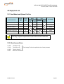
1
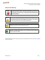
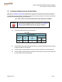
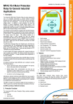
MPA3 V6.3 MOTOR PROTECTION RELAY
(Suitable for Mining Applications)
USER MANUAL
Issue: R0 Nov 2010
CRN: 8168
Ampcontrol User Manual Part No: 143401
Designed and Manufactured in Australia by Ampcontrol CSM Pty Limited.
MPA3 V6.3 MOTOR PROTECTION RELAY MANUAL
Issue: R0, Date: 11/2010, CRN: 8168
Safety and other Warnings
WARNING!
CAUTION!
This safety alert symbol identifies important safety messages in this manual and
indicates a potential risk of injury or even death to the personnel. When you see this
symbol, be alert, your safety is involved, carefully read the message that follows, and
inform other operators.
This safety alert symbol identifies important information to be read in order to ensure the
correct sequence of work and to avoid damage or even destruction of the equipment,
and reduce any potential risk of injury or death to the personnel.
Supplementary information not directly affecting safety or damage to equipment. Carefully read
the message that follows, and inform other relevant personnel.
Information concerning possible impact on the environment and actions required for
prevention and proper response.
If this document is being read via a computer the hyper links may be used (Press control and click on the blue highlighted
text to go to that topic).
MPAB010 R0.docx
Page 1
MPA3 V6.3 MOTOR PROTECTION RELAY MANUAL
Issue: R0, Date: 11/2010, CRN: 8168
Copyright Notice
No part of this publication may be reproduced, transmitted or transcribed into any language by any means without the
express written permission of Ampcontrol CSM Pty Ltd, 7 Billbrooke Close, Cameron Park. NSW 2285, Australia.
Disclaimer
Ampcontrol CSM Pty Ltd will make no warranties as to the contents of this documentation and specifically disclaims any
implied warranties or fitness for any particular purpose.
Ampcontrol further reserves the right to alter the specification of the system and/or manual without obligation to notify any
person or organisation of these changes.
Before You Begin
We would like to take a moment to thank you for purchasing the MPA3 V6 Motor Protection Relay.
WARNING!
To ensure the correct and safe operation of this equipment the user is to
become completely familiar with the safety requirements and correct operating
procedures detailed in this user manual.
Ampcontrol Electronics Contact details:
Ampcontrol CSM Pty Ltd
7 Billbrooke Close, Cameron Park, NSW, 2285
P +61 2 4903 4800 | F +61 2 4903 4888
EMAIL: [email protected]
WEB: www.ampcontrolgroup.com
MPAB010 R0.docx
Page 2
MPA3 V6.3 MOTOR PROTECTION RELAY MANUAL
Issue: R0, Date: 11/2010, CRN: 8168
Table of Contents:
Safety and other Warnings ............................................................................................................................................ 1
Copyright Notice ............................................................................................................................................................ 2
Disclaimer ...................................................................................................................................................................... 2
Before You Begin .......................................................................................................................................................... 2
Ampcontrol Electronics Contact details: ........................................................................................................................ 2
1
Receiving and Storage......................................................................................................................................... 5
1.1 Receiving ........................................................................................................................................................ 5
1.2 Storage after Delivery ..................................................................................................................................... 5
1.3 Unpacking of Equipment ................................................................................................................................. 5
2
General safety...................................................................................................................................................... 6
2.1 Personnel Safety Warnings ............................................................................................................................. 6
2.1.1
Relevant Personnel ............................................................................................................................. 6
2.1.2
Safety Communication ........................................................................................................................ 6
2.2 Safe Use of Equipment ................................................................................................................................... 6
2.2.1
Changes to Equipment ........................................................................................................................ 6
2.2.2
Equipment Knowledge ........................................................................................................................ 6
2.3 Conditions to Maintain Intrinsically Safe Rating .............................................................................................. 7
3
Overview of MPA3 V6 Relay ................................................................................................................................ 8
3.1 General Description ........................................................................................................................................ 8
3.2 Protection Functions ....................................................................................................................................... 8
3.3 Optional Monitoring Modules .......................................................................................................................... 9
3.3.1
MPA-M ................................................................................................................................................ 9
3.3.2
MPA-I .................................................................................................................................................. 9
3.3.3
MPA-M (e) ........................................................................................................................................... 9
4
Basic Display Operation ....................................................................................................................................... 9
4.1 Status Messages ........................................................................................................................................... 10
5
Current Related Functions ................................................................................................................................. 14
5.1 Overload Protection ...................................................................................................................................... 14
5.2 Short Circuit Protection ................................................................................................................................. 16
5.3 Phase Current Balance ................................................................................................................................. 16
5.4 Residual Current Signal ................................................................................................................................ 17
6
Earth Leakage Protection .................................................................................................................................. 17
7
Motor Contactor Fail Protection ......................................................................................................................... 17
8
Metering ............................................................................................................................................................. 18
9
Insulation Test.................................................................................................................................................... 18
10 Under-voltage Trip ............................................................................................................................................. 20
11 PT-100 RTD Temperature Protection ................................................................................................................ 20
12 Analogue Output ................................................................................................................................................ 21
13 Communications ................................................................................................................................................ 21
13.1 Modbus Communications........................................................................................................................... 22
13.1.1
Modbus Configuration ....................................................................................................................... 22
13.1.2
Modbus Commands .......................................................................................................................... 22
13.1.3
Modbus Status .................................................................................................................................. 22
13.2 EtherNet/IP Communications ..................................................................................................................... 23
14 Energy Storage Module ..................................................................................................................................... 24
MPAB010 R0.docx
Page 3
MPA3 V6.3 MOTOR PROTECTION RELAY MANUAL
Issue: R0, Date: 11/2010, CRN: 8168
15 MPA Alarm Functions ........................................................................................................................................ 24
15.1 High Current Alarm: ................................................................................................................................... 24
15.2 Overload Alarm: ......................................................................................................................................... 24
15.3 Under Current Alarm: ................................................................................................................................. 24
15.4 Earth Leakage Alarm: ................................................................................................................................ 24
16 Adjustable Settings ............................................................................................................................................ 25
16.1 Common Settings ...................................................................................................................................... 25
16.2 Modbus Settings ........................................................................................................................................ 25
16.3 Ethernet Settings ....................................................................................................................................... 26
16.4 Changing Settings...................................................................................................................................... 26
17 Digital Inputs ...................................................................................................................................................... 27
18 Output Relays .................................................................................................................................................... 27
19 Event Log ........................................................................................................................................................... 27
20 Advanced Display Operation ............................................................................................................................. 30
21 Time & Date ....................................................................................................................................................... 30
22 MPA Specifications ............................................................................................................................................ 31
23 MPA Comms. Address Table ............................................................................................................................. 32
24 Maintenance & Disposal .................................................................................................................................... 37
24.1 Equipment Maintenance ............................................................................................................................ 37
24.2 Disposal of System Parts ........................................................................................................................... 37
25 Equipment List ................................................................................................................................................... 38
25.1 Base Models and Options Part Nos. .......................................................................................................... 38
25.2 Miscellaneous Extras ................................................................................................................................. 38
Appendix A – Drawings ............................................................................................................................................... 39
Appendix B – Approvals .............................................................................................................................................. 44
MPAB010 R0.docx
Page 4
MPA3 V6.3 MOTOR PROTECTION RELAY MANUAL
Issue: R0, Date: 11/2010, CRN: 8168
1 Receiving and Storage
1.1 Receiving
All possible precautions are taken to protect the equipment against damage or losses during shipment, however before
accepting delivery, check all items against the packing list or Bill of Lading. If there are shortages or evidence of physical
damage, notify Ampcontrol immediately.
Notify Ampcontrol within 7 days (maximum) in case of shortages or discrepancies, according to the packing list. This
action will help ensure a speedy resolution to any perceived problems. Keep a record of all claims and correspondence.
Photographs are recommended.
Where practicable do not remove protective covers prior to installation unless there are indications of damage. Boxes
opened for inspection and inventory should be carefully repacked to ensure protection of the contents or else the parts
should be packaged and stored in a safe place. Examine all packing boxes, wrappings and covers for items attached to
them, especially if the wrappings are to be discarded.
1.2 Storage after Delivery
When the equipment is not to be installed immediately, proper storage is important to ensure protection of equipment and
validity of warranty.
All equipment should be stored indoors protected from the elements in a cool dry area. If storing on the ground, ensure
that the storage area is not an area where water will collect.
1.3 Unpacking of Equipment
The method of packing used will depend on the size and quantity of the equipment. The following cautions should be
interpreted as appropriate.
CAUTION!
Take care when unpacking crates as the contents may have shifted during transport.
Make sure that cable drums are securely attached to their shipping pallets before
attempting to move them (if applicable).
The disposal of packaging materials, replaced parts, or components must comply with
environmental restrictions without polluting the soil, air or water.
Ensure that any timber and cardboard used as packaging is disposed of in a safe and
environmentally responsible manner.
Where possible, dispose of all waste products i.e. oils, metals, plastic and rubber products by
using an approved recycling service centre.
MPAB010 R0.docx
Page 5
MPA3 V6.3 MOTOR PROTECTION RELAY MANUAL
Issue: R0, Date: 11/2010, CRN: 8168
2 General safety
2.1 Personnel Safety Warnings
2.1.1
Relevant Personnel
Ensure all personnel directly responsible or involved with the installation, operation and maintenance of the equipment
reference this manual in conjunction with any relevant risk assessments to identify all foreseeable hazards.
2.1.2
Safety Communication
All safety instructions and design requirements within this manual must be communicated to all users. These
requirements are necessary to identify and control any foreseeable risk associated with this piece of equipment. In the
event of any damage or malfunction that results in the potential to harm the health or safety of any person; the
owner/operator should notify the manufacturer immediately.
2.2 Safe Use of Equipment
Equipment supplied has been manufactured within the guide lines of the relevant Australian Standards and state
legislative requirements. Equipment identified within this manual has been designed for a specific intended purpose;
therefore any modification or damage must be reported to the manufacturer for repair.
The instructions within this manual must be observed as an aid towards achieving maximum safety during operation.
2.2.1
Changes to Equipment
Changes in the design and modifications to the equipment are not permitted
2.2.2
Equipment Knowledge
Experience with, or understanding of, this equipment is essential for the safe installation and removal of the equipment. If
in doubt, contact Ampcontrol immediately.
Mechanical and or Electrical installation, and maintenance of plant and equipment, must only be carried out by
appropriately trained, qualified and competent personnel.
MPAB010 R0.docx
Page 6
MPA3 V6.3 MOTOR PROTECTION RELAY MANUAL
Issue: R0, Date: 11/2010, CRN: 8168
2.3 Conditions to Maintain Intrinsically Safe Rating
Refer also to Certificate of Conformity in Appendix B – Approvals at the back of this manual of this manual
The ISB/1 Battery Assembly Module is certified as complying with the relevant standards for intrinsically safe electrical
equipment with the following grouping and classification:
Ex ia I 150°C (-20°C to +40°C ambient temperature range) Underground Coal Mines
WARNING!
a)
To ensure that this equipment does not contravene the Certificate of
Conformity certain conditions must be met; they are as follows:
The following entity parameters must be observed:
Um = 132V
Entity Parameters
Apparatus
Uo
(V)
Io
(mA)
ISB/1
3.7
0.5
Group I
Co
(µF)
10000
Lo
(mH)
1000
b)
The ISB/1 Battery Assembly Module shall be installed in an appropriately certified enclosure providing
a Degree of Protection of at least IP20.
c)
The ISB/1 Battery Assembly Module shall only be removed or replaced in a nonhazardous area.
d)
The ISB/1 Battery Assembly Module is considered intrinsically safe only when the mains power and
any other power sources are de-energised.
MPAB010 R0.docx
Page 7
MPA3 V6.3 MOTOR PROTECTION RELAY MANUAL
Issue: R0, Date: 11/2010, CRN: 8168
3 Overview of MPA3 V6 Relay
3.1 General Description
The Ampcontrol MPA Motor Protection Relay has been designed to provide optimum overload protection of small to
medium sized 415 V motors used on conveyors, pumps, fans and compressors. It can also be used with higher voltage
motors. In addition to motor protection the relay has features to monitor temperature, provide alarms before a trip
condition and through a 50 record event log allows diagnosis of a problem after a fault has occurred. The standard
current transformers supplied with the MPA Protection Relay enable protection of motors with full load currents ranging
from 5.125 A to 640 A. The selected full load current can be set to one of 224 values across the range.
The MPA Motor Protection Relay has 5 digital inputs, which feed into a microprocessor unit. The microprocessor has
been programmed to control three output relays: MTR (Main Trip Relay), ALM (Alarm Relay) and AUX (Auxiliary Relay).
Inputs are also provided for PTC Thermistors and current transformers.
A two-line backlit LCD display used in conjunction with a keypad provides an easy to use interface. The display provides
easy access to all available information. A simple procedure allows adjustment of the relay’s settings.
The Energy Storage Module allows the MPA Relay to function normally for a period of two (2) seconds during an extreme
power dip or power loss.
The MPA’s event log and adjustable settings are battery backed with an approved IS Battery - AUS Ex 01.2533X Ex ia I
(when mains power is de-energised). The battery is not user replaceable (return the MPA Relay to Ampcontrol for
replacement of the approved battery).
The MPA is housed in an enclosure suitable for flush mounting in a 135 mm square cut out and has robust plug in
connectors on the rear.
3.2 Protection Functions
The Ampcontrol MPA motor Protection Relay provides protection functions for:
§
Overload
§
Short Circuit
§
Earth Leakage (Designed and Tested to AS2081.3-1988)
§
Motor Contactor Fail
§
Phase Current Unbalance
§
Undercurrent/Over-current Alarms
§
Over Temperature - PTC Thermistor
§
Optional Under-voltage
§
Optional Insulation Test
§
Optional PT-100 RTD Temperature Protection
MPAB010 R0.docx
Page 8
MPA3 V6.3 MOTOR PROTECTION RELAY MANUAL
Issue: R0, Date: 11/2010, CRN: 8168
3.3 Optional Monitoring Modules
3.3.1
MPA-M
This optional monitoring module (MPA-M) can be utilised to provide the following features:
3.3.2
§
Five PT-100 RTD inputs, which are arranged in two groups; three for the stator and two for the bearings.
§
RS485 Modbus RTU communication port that can be connected to Motor Starter PLC's, or a central
monitoring system, for continuous monitoring and fault-finding.
§
A 0-20 mA/4-20 mA Analogue Output.
MPA-I
This is an optional insulation test module which allows frequent testing of motor insulation.
3.3.3
MPA-M (e)
This optional monitoring module has the same features as the MPA-M module except the RS485 Modbus communication
port is replaced by an EtherNet/IP communications port.
4 Basic Display Operation
The facia of the MPA Motor Protection Relay has a two line 16-character backlit LCD display, Status LED and a tactile
keypad.
The layout of the display structure is shown on the ‘MPA Display Map’. The display level is changed with the Up/Down
arrow keys and the Left/Right arrow keys control the display Position. See drawing ‘MPA Display Map’ MPAB003,
Appendix A – Drawings.
The ENT and ESC keys are used to modify settings and provide hyper jump access to the display structure.
The Reset key allows reset following a trip condition.
The Status LED is a single bi-coloured LED that can be viewed some distance from the relay. Status indication is as
follows:
MPA Status
LED Colour
LED Flash
OK
Green
4 Hz
Alarm
Red
4 Hz
Trip
Red
1 Hz
The ‘Motor Status Page’ is the default screen on power up and shows the current status of the MPA Protection Relay. A
one-line status message is displayed and if more than one message is active the display cycles through all active
messages at 1 second intervals.
MPAB010 R0.docx
Page 9
MPA3 V6.3 MOTOR PROTECTION RELAY MANUAL
Issue: R0, Date: 11/2010, CRN: 8168
4.1 Status Messages
The following table (Table 4.1) shows a list of the twenty-three status messages and the category (type) of the messages.
Messages are cleared according to their message category.
Type 1: Messages are triggered by their respective functions and cleared by operating the <RESET> key/digital input.
Type 2: Messages are triggered and cleared automatically.
Type 3: Messages are triggered by their respective trip functions. Messages are cleared by closing the lock input, and
then operating the <RESET> key/digital input, and then releasing the lock input.
Message and Type
Motor O/L Trip
Short Cct Trip
Cur. bal. Trip
Earth Leak
Comment
1/2
Over Current Function Tripped
3
Short Circuit Function Tripped
1
Phase Current Balance Function Tripped
1
Earth Leakage Function Tripped
1
Residual Current Function Tripped
1
Thermistor PTC Function Tripped
1
Under Volts Function Tripped
Trip
Residual I
Trip
Thermistor
Trip
Under Volts
Trip
MPAB010 R0.docx
Page 10
MPA3 V6.3 MOTOR PROTECTION RELAY MANUAL
Issue: R0, Date: 11/2010, CRN: 8168
Message and Type
MPA Memory
Comment
1
Corrupted memory in relay’s stored settings
1
RTD Group 1 Function Tripped
1
RTD Group 2 Function Tripped
1
Main Contactor Fail Function Tripped
1
Insulation Test Function Tripped
2
Phase current above set threshold level
2
Thermal Accumulator above set threshold level
Error
RTD Group1
Trip
RTD Group2
Trip
Motor Cont.
Fail
Insulat.Test
Trip
High Cur.
Alarm
Over Load
Alarm
MPAB010 R0.docx
Page 11
MPA3 V6.3 MOTOR PROTECTION RELAY MANUAL
Issue: R0, Date: 11/2010, CRN: 8168
Message and Type
Under Cur.
Comment
2
Phase current below set threshold level
2
Earth leakage Current is above the set threshold level
2
Group 1Temperature above set threshold level
2
Group 2 Temperature above set threshold level
Alarm
Earth Leak
Alarm
RTD Group1
Alarm
RTD Group2
Alarm
Insulat. Test
1/2
Test result at alarm level
Alarm
Testing
2
In process of Insulation Test
2
Insulation test disabled.
2
Insulation Test above the set threshold
Insulat.
IT Enable Open
Insulat. Test
OK
MPAB010 R0.docx
Page 12
MPA3 V6.3 MOTOR PROTECTION RELAY MANUAL
Issue: R0, Date: 11/2010, CRN: 8168
Message and Type
Motor Stopped
Motor Amps:
Comment
2
MCI Open
2
MCI Closed
Table 4.1
MPAB010 R0.docx
Page 13
MPA3 V6.3 MOTOR PROTECTION RELAY MANUAL
Issue: R0, Date: 11/2010, CRN: 8168
5 Current Related Functions
5.1 Overload Protection
The motor overload function is based on a thermal model of the motor. The three phase currents are squared to provide
the I2R heating input to the motor model. The selected ‘Stopped Cooling Ratio’ determines the cooling output for the
model.
The state of the thermal model is shown by the ‘Thermal Accumulator’, which can be viewed on the 'Current/Volts
Information' level on the display. The thermal accumulator represents the motor temperature. When it reaches 100% a
“Motor Overload” trip occurs.
The full load current is selected via the ‘I (100%)’ setting (Level 7, Position 1) and can be set between 5.125 A and 640 A
in 224 increments as shown in Table 5.1, ‘Current Settings’.
MPA Full Load Current Selection Table - Amps
5.125
5.250
5.375
5.500
5.625
5.750
5.875
6.000
6.125
6.250
6.375
6.500
6.625
6.750
6.875
7.000
7.125
7.250
7.375
7.500
7.625
7.750
7.875
8.000
8.500
8.750
9.000
9.250
9.500
9.750
10.000
10.25
10.50
10.75
11.00
11.25
11.50
11.75
12.00
12.25
12.50
12.75
13.00
13.25
13.50
13.75
14.00
14.25
14.50
14.75
15.00
15.25
15.50
15.75
16.00
17.00
17.50
18.00
18.50
19.00
19.50
20.00
20.5
21.0
21.5
22.0
22.5
23.0
23.5
24.0
24.5
25.0
25.5
26.0
26.5
27.0
27.5
28.0
28.5
29.0
29.5
30.0
30.5
31.0
31.5
32.0
34.0
35.0
36.0
37.0
38.0
39.0
40.0
41
42
43
44
45
46
47
48
49
50
51
52
53
54
55
56
57
58
59
60
61
62
63
64
68
70
72
74
76
78
80
82
84
86
88
90
92
94
96
98
100
102
104
106
108
110
112
114
116
118
120
122
124
126
128
136
140
144
148
152
156
160
164
168
172
176
180
184
188
192
196
200
204
208
212
216
220
224
228
232
236
240
244
248
252
256
272
280
288
296
304
312
320
328
336
344
352
360
368
376
384
392
400
408
416
424
432
440
448
456
464
472
480
488
496
504
512
544
560
576
592
608
624
640
Table 5.1 Current Settings
MPAB010 R0.docx
Page 14
MPA3 V6.3 MOTOR PROTECTION RELAY MANUAL
Issue: R0, Date: 11/2010, CRN: 8168
The trip time is selected via the ‘6xI Trip t’ setting (Level 7, Position 2). It is a function of the current and the selected trip
time curve. The drawing ‘MPA Motor Overload and Short Circuit Trip Times’, MPAB007, in Appendix A – Drawings shows
the trip time curves.
The fifteen motor overload curves allow trip settings from 3 to 40 seconds at six times FLC and are shown for both cold
and hot conditions. The hot curve corresponds to the trip time after the motor has been running at the selected full load
current indefinitely.
The trip time can be calculated as follows:
é 2 1.1238 A% ù
I 100 ú
Trip Time = C ´ 31.53 ´ ln ê
ê
ú
êë I 2 - 1.1238 úû
Where:
C
= Curve Selected
I
= Current (FLC = 1)
A% = Initial Thermal Accumulator Value
The motor manufacturer's data should always be consulted to select the appropriate settings for the motor being
protected. Typically, the capacity of a cold motor is given at six times its rated current.
The MPA Relay's trip curves can then be used to select the trip time curve, which best suits the motors overload capacity.
The motor overload trip latches once the thermal accumulator reaches 100% and can only be reset once the thermal
accumulator falls below a preset value. The pre-set value is selected via the ‘O/L Reset’ setting (Level 7, Position 3) and
can be set to 30%, 40%, 50%, 60%, 70%, 80%, 90%, A-30%, A-40%, A-50%, A-60%, A-70%, A-80%, A-90%. The Asettings automatically reset a motor overload trip once the thermal accumulator falls below the set value. Otherwise the
trip has to be reset manually by pressing the keypad ‘RESET’ button or activating the ‘RESET’ digital input once the
thermal accumulator has fallen below the set value.
An emergency restart on a hot motor can be achieved by zeroing the thermal accumulator memory. This is done by
closing the E/start input and reset key/digital input simultaneously for 1.5 seconds.
CAUTION!
Repeated attempts to restart the motor in this condition may damage the
motor.
The ‘Stopped Cooling Ratio’ modifies the cooling output of the thermal model when the motor is stopped. This can be
used to account for reduced cooling capacity of the motor when it is not running (motor run status monitored via MCI
digital input).
The ratio is selected via the ‘S-Cool Ratio’ setting (Level 7, Position 4) and is adjustable from 1.0 to 5.0. A cooling
multiplier of 1 means the cooling is independent of whether the motor is running or not - e.g. a water-cooled motor.
Protection for a fan-cooled motor is based on a setting of 2.5, however, for the best protection consult the motor
manufacturer.
MPAB010 R0.docx
Page 15
MPA3 V6.3 MOTOR PROTECTION RELAY MANUAL
Issue: R0, Date: 11/2010, CRN: 8168
5.2 Short Circuit Protection
The short circuit function has a definite time characteristic. If the current exceeds the selected level for the pre-set time
then a trip occurs. The short circuit function trips the auxiliary relay. (The AUX relay is normally energised, and drops out
when tripped).
The short circuit trip level is selected via the ‘SC I Trip’ setting (Level 7, Position 6) and is a multiple of the selected full
load current, from 3.0 to 10 times FLC, in steps of 0.5. The trip level may be set to ‘off’ to disable the SC protection.
WARNING!
Setting the trip level to ‘OFF’ disables the SC function and is intended to only ever be
used with coordinated SC tripping circuit breakers or when the SC function is
performed external to the MPA. Use extreme caution when choosing this option.
The trip time is selected via the ‘Sc Trip t’ setting (Level 7, Position 7) and is adjustable from 20 to 160 ms. See
Drawing MPAB007 in Appendix A – Drawings.
To reset the relay following a short circuit trip it is necessary close the lock input, then operate the reset key/digital input,
and then release the lock input.
5.3 Phase Current Balance
The current balance measurement ‘Ib’ is displayed on the ‘Current/Volts Information’ Page, Level 1, Position 1 and is
calculated as:
Ibal
Where:
MAX D I x 100%
=
Iave
MAX D I
Iave
=
=
Average of the 3 phase currents
The maximum deviation of a phase current from the average
Phase current balance protection is selected via the ‘I Bal Trip’ setting (Level 7, Position 5).
The trip level is selectable at 5%, 10%, 20%, 50% and off.
The phase current balance protection is inhibited until the average current exceeds both 20% of the selected full load
current and the selected balance trip level.
MPAB010 R0.docx
Page 16
MPA3 V6.3 MOTOR PROTECTION RELAY MANUAL
Issue: R0, Date: 11/2010, CRN: 8168
5.4 Residual Current Signal
The three phase current signals are summed electronically in the MPA to produce a residual current signal that can be
used to detect earth fault currents. If the residual current signal exceeds the trip level for the selected trip time, a trip
occurs, tripping the MTR relay. The fault is latched.
To reset the relay following a residual current trip, operate the reset key/digital input.
The % residual current is displayed as ‘Ir’ on the ‘Current/Volts Information’ Page, Level 1, Position 2.
The trip level is selected via the ‘Ires Trp’ setting (Level 7, Position 14) and is adjustable from 10% to 100% FLC. The trip
time is selected via the ‘Ir Time’ setting (Level 7, Position 15) and is adjustable from 100 ms to 5 sec. Setting the trip
level to ‘Off’ disables this function.
The residual current function can be used even if a core balance toroid is used for earth
leakage protection. It can be used to provide some detection of wiring/CT/internal relay
faults.
6 Earth Leakage Protection
The earth leakage protection function is designed and tested to AS2081.3-1988 and uses a 100:1 core balance toroid to
measure the earth fault current. A definite time operating characteristic is provided with adjustable trip sensitivity and
time delay. If the earth leakage signal exceeds the trip level for the selected trip time, a trip occurs, tripping the MTR
relay. The fault is latched.
The % leakage current is displayed on the 'Current/Volts Information' Page as ‘Ie’ shown as a % of the selected trip level.
When the leakage reaches 100% for the selected time delay a trip occurs.
To reset the relay following an earth leakage trip, operate the reset key/digital input.
The trip level is selected via the ‘EL:’ setting (Level 7, Position 11) and is adjustable between 0.001 A to 0.005 A x CT
ratio. Trip settings are 100-500 mA with the approved 100:1 Toroid. Setting the trip level to ‘Off’ will disable this function.
The time delay is selected via the ‘EL Time’ setting. Settings are Instantaneous and are adjustable between 155 ms and
475 ms.
For alarm functions see ‘MPA Alarm Functions’, Section 15.
7 Motor Contactor Fail Protection
The status of the motor contactor is monitored via the ‘MCI’ digital input. If the MPA trips its MTR relay then it expects to
see the MCI open. Failure to open within 1 second will cause a ‘Motor Contactor Fail’ trip that operates the AUX relay.
The AUX relay should be arranged to provide backup tripping of the motor, usually through a main circuit breaker.
To reset the relay following a motor contact failure trip, operate the reset key/digital input.
The status of the MCI input can be viewed on the ‘MPA I/O Status Information’ Page, Level 5, Position 1.
MPAB010 R0.docx
Page 17
MPA3 V6.3 MOTOR PROTECTION RELAY MANUAL
Issue: R0, Date: 11/2010, CRN: 8168
8 Metering
The MPA Motor Protection relay provides the following information:
§
Phase Currents
§
Current Balance
§
% Residual Current
§
% Leakage Current
§
Trip Accumulator (thermal capacity indicating how close to a trip condition)
§
Result of Insulation Test (MPA-I option)
§
% Phase voltage (MPA-I option)
§
Stator Temperature (MPA-M option)
§
Bearing Temperature (MPA-M option)
9 Insulation Test
The optional Insulation Test Module (MPA-I) allows the insulation resistance of 415 V motors and/or installations to be
tested with 500 VDC to earth. Selectable trip and alarm thresholds can be triggered if the resistance to earth is too low.
This test can only be performed when the motor is stopped (MCI open). The external ‘Insulation Test Enable’ (ITE)
terminals must also be bridged to allow a test to be performed.
An insulation test (IT) is activated by the option selected by the ‘ITst Mode’ setting (Level 7, Position 16). The options
are:
Setting
Di1
Key
Di1/Key
Off
Comment
Di1 digital input activates IT
Keyboard Test Key activates IT
Either one of the above activate IT
IT disabled
The ‘ITstatus’ is shown on the ‘Insulation Test Information’ Page, Level 4, Position 1 and indicates the following:
Status
No
Comment
IT Module not installed
ITM
Mtr
Motor Running (IT Disabled)
Run
Enabl
MPAB010 R0.docx
IT Module installed but Enable Input (ITE) not bridged
Page 18
MPA3 V6.3 MOTOR PROTECTION RELAY MANUAL
Issue: R0, Date: 11/2010, CRN: 8168
e?
Test?
Testi
Ready to test, waiting IT input according to ‘IT Mode’ setting
Test in progress. IT input must remain for three (3) seconds
ng
Test
IT result was OK, message remains until loss of IT input
OK
Alarm
IT result triggered an alarm, message remains until loss of IT
input
ed
Tripp
IT result triggered a trip, message remains until trip is reset
ed
MPAB010 R0.docx
Page 19
MPA3 V6.3 MOTOR PROTECTION RELAY MANUAL
Issue: R0, Date: 11/2010, CRN: 8168
The ‘testing’ phase takes 3 seconds during which time the IT input must remain active in order to obtain a valid result.
The last IT result is retained in memory and displayed until a subsequent test or power down.
The measurement range is 125 MW down to 0.8 MW, with <0.8 MW displayed for values less than 0.8 MW.
The trip level is selected via the ‘ITst Trp’ setting (Level 7, Position 17) and is adjustable between 1.0 MW and 100 MW.
The alarm level is selected via the ‘ITst Alm’ setting (Level 7, Position 18) and is adjustable between 1.0 MW and 100
MW.
A trip takes priority if both trip and alarm conditions occur as a result of an IT.
IT alarms self-clear when a subsequent IT result is greater than the selected alarm value. They can also be reset
manually by operating the reset key/digital input.
IT trips are latched and prevent subsequent IT’s until the trip is manually reset by operating the reset key/digital input.
Setting either the ‘ITst Trp’ or ‘ITst Alm’ setting to ‘OFF’ disables that function.
10 Under-voltage Trip
The optional Insulation Test Module (MPA-I) allows Under-voltage protection that is enabled as soon as the main
contactor is closed (indicated by closing the MCI input). If any of the phase voltages drop below the selected trip setting
of the nominal line voltage for 1.5 Seconds then the MTR relay is de-energised.
To reset the relay following an under-voltage trip, operate the reset key/digital input.
The trip level is selected via the ‘UV Level’ setting (Level 7, Position 19) and is adjustable from 40% to 95%. Setting the
trip level to ‘Off’ disables this function.
11 PT-100 RTD Temperature Protection
The optional Monitoring Module (MPA-M) allows temperature monitoring of 5 PT-100 RTDs, connected in 3-wire mode.
The three-wire connection allows compensation of installation lead resistance. The RTD inputs are configured as
‘Group1’ RTD’s (1, 2 and 3) and ‘Group 2' RTD’s (4 and 5). Each Group has a separate alarm and trip level. Group 1 (G1)
is intended for monitoring stator temperature while group 2 (G2) is intended for bearing temperature.
The Trip levels are selected via the ‘RTD G1 T:’ and/or ‘RTD G2 T:’ settings (Level 7, Position 20 and 22) and are
adjustable from 60°C to 200°C. If the measured value exceeds the trip level for 2 seconds, a trip occurs. Trip’s are
latched, and cannot be reset by the reset/digital input until the temperature falls back below the trip threshold. Setting the
trip level to ‘Off’ disables this function.
The Alarm levels are selected via the ‘RTD G1 A:’ and/or ‘RTD G2 A:’ settings (Level 7, Position 21 and 23) and are
adjustable from 50°C to 200°C. If the measured value exceeds the alarm level for 2 seconds, an alarm occurs. Alarm’s
self clear once the measured value falls below selected value for 2 seconds. Setting the alarm level to ‘Off’ disables this
function.
A trip takes priority if both trip and alarm conditions occur as a result of a RTD’s temperature.
MPAB010 R0.docx
Page 20
MPA3 V6.3 MOTOR PROTECTION RELAY MANUAL
Issue: R0, Date: 11/2010, CRN: 8168
The RTD temperatures for group 1 and group 2 can be viewed on the ‘Temperature Information’ Page, Level 2, Positions
1 and 2 respectively. The measurement range is 0°C to 210°C. Values greater than 210°C represent an error condition
as follows:
Error
Comment
246
Error code 246 results if the RTD terminals are left open
circuit or the RTD resistance rises above 330 W. Unused
RTD inputs can be terminated with a 100 W resistor
(0°C) to avoid the error code.
245
Error code 245 results if the RTD is short-circuited or its
resistance falls below 80 W.
The RTD’s will operate correctly if the combined installation cable resistance to the PT-100 RTD is less than 40 W.
12 Analogue Output
The optional Monitoring Module (MPA-M) provides an isolated analogue output configurable as 0-20 mA or 4-20 mA.
The output is selected via the ‘An OP:’ setting (Level 7, Position 24) to continuously monitor one of the following sections:
§
Trip Accumulator
(20 mA = 100%)
§
Average Current
(20 mA = 1000%)
§
Earth Leakage
(20 mA = 100%)
§
RTD Temp (0-200 °C)
(20 mA = 200°C)
§
Current Balance
(20 mA = 100%)
§
Phase Voltage (A phase)
(20 mA = 120%)
The analogue output status is shown on the ‘MPA I/O Status Information’ Page, Level 5, Position 4. The value shown for
‘Analog Out’ is related to the analogue output current according to:
Iout (mA) = Displayed Value x 8.1458 x 10-05
13 Communications
When the MPA is ordered with an optional monitoring module a communications port is provided. This allows for the
connection of the MPA to PLC or SCADA systems. Two different monitoring modules are available providing a choice
between RS485 Modbus RTU and EtherNet/IP.
With either communications option, the same data is available over the network.
Communications Address Table’ for accessible data.
MPAB010 R0.docx
See Section 23, ‘MPA
Page 21
MPA3 V6.3 MOTOR PROTECTION RELAY MANUAL
Issue: R0, Date: 11/2010, CRN: 8168
13.1 Modbus Communications
13.1.1 Modbus Configuration
The baud rate is selected via the ‘Modbus:’ setting (Level 7, Position 25) and is selectable between 1200 and 9600
Baud, with even, odd, or no parity. One stop bit is used in conjunction with parity, while two stop bits are used with no
parity.
The half-duplex 3-wire RS485 communications interface allows up to 31 devices to be multi-dropped onto a single master
communication line. The MPA’s Modbus Slave address is selected via the ‘Modbus Ad:’ setting (Level 7, Position 26)
and is adjustable between 1 and 31.
13.1.2 Modbus Commands
The following Modbus commands are supported:
Modbus CMD
Comment
03
Read Holding Registers
04
Read Input Registers
06
Store Single Register
16
Store Multiple Registers
Valid read registers are in the range from 1 to 96. An attempt to read a register outside this range will result in an
exception scan. Currently, only the first 64 registers contain valid data. The range from 65 to 96 is for future expansion
The range from 65 to 96 are also write addresses, the only active write address is 65 which is folded back to the read
only address 20.
Supported Modbus exception responses are:
Modbus Exception
Comment
01
Illegal Function
02
Illegal Data Address
03
Illegal Data Value
13.1.3 Modbus Status
The MPA Modbus status is shown on the ‘MPA I/O Status Information’ Page, Level 5, Position 4 and indicates the
following:
Status
Comment
MPAB010 R0.docx
No Opt Card
No monitoring card installed
No Mbus RxD
Monitoring card installed, but there
has not been a valid Modbus
transaction in the last 30 seconds
Online…OK
Monitoring card installed, a valid
Modbus transaction has occurred
in the last 30 seconds
Page 22
MPA3 V6.3 MOTOR PROTECTION RELAY MANUAL
Issue: R0, Date: 11/2010, CRN: 8168
13.2 EtherNet/IP Communications
13.2.1 Ethernet Network Configuration
The Ethernet connection allows for the setting of the MPA’s IP Address, Default Gateway Address and Subnet Mask.
The IP Address can only be set statically using the MPA configuration menu. Dynamic address configuration protocols
such as DHCP or BOOTP cannot be used.
Both the IP address and the default gateway are set using four individual parameters; one for each byte of the address.
The subnet mask is set as a single number between 0 and 32. This number is the number of bits used in the subnet
mask.
Example configuration:
IP Address:
192.168.10.25
Default Gateway: 192.168.11.254
Subnet Mask:
255.255.0.0
IP Address
IP Addr 3
IP Addr 2
IP Addr 1
IP Addr 0
192
168
10
25
Gateway
Gateway 3
Gateway 2
Gateway 1
Gateway 0
192
168
11
254
SubnetMsk
16
13.2.2 EtherNet/IP Settings
The MPA provides process data to the originator of an EtherNet/IP connection using I/O messaging. The connection can
be established by creating a generic Ethernet Module and setting the following parameters:
Assembly Instance
Size
Input
101
65
Output
102
1
Configuration
128
0
Comms Format:
Data - INT
Requested Packet Interval:
> 150 ms
The MPA data should be available as Input data once an EtherNet/IP Connection has been established.
MPAB010 R0.docx
Page 23
MPA3 V6.3 MOTOR PROTECTION RELAY MANUAL
Issue: R0, Date: 11/2010, CRN: 8168
14 Energy Storage Module
The Energy Storage Module (MPA-E) allows the MPA Relay to function normally for a period of two (2) seconds during
an extreme power dip or power loss.
15 MPA Alarm Functions
The MPA has several standard alarm functions. If any are triggered, the Alarm Relay (ALM) picks up. Each has a
selectable alarm level, and can be disabled. Generally the alarms are self-resetting once the alarm condition is removed.
Optional modules MPA-I and M contain alarm settings for Insulation Test and Temperature Monitoring.
15.1 High Current Alarm:
This is triggered by the phase currents exceeding the selected threshold. It is selected via the ‘HI I Alarm:’ setting
(Level 7, Position 8) and is adjustable from 100% to 600% FLC. The highest of the three phase currents is used.
Time delay = 1 sec. Setting the alarm level to ‘Off’ disables this function.
15.2 Overload Alarm:
This is triggered by the thermal accumulator exceeding the selected threshold. It is selected via the ‘O/Load Alm:’
setting (Level 7, Position 9) and is adjustable from 50% to 95%. Time delay = 2 Sec. A motor overload trip
overrides this alarm. Setting the alarm level to ‘Off’ disables this function.
15.3 Under Current Alarm:
This is triggered by the phase current falling below the selected threshold. It is selected via the ‘LO I Alm:’ setting
(Level 7, Position 10) and is adjustable from 32% to 96%. This alarm is only activated when the motor is running
(MCI input closed). Time delay = 2 sec. Setting the alarm level to ‘Off’ disables this function.
15.4 Earth Leakage Alarm:
This is triggered when the earth leakage current exceeds a set level. The alarm level is selected via the ‘E/L
Alarm:’ setting (Level 7, Position 13) and can be set to 20%, 50%, and 80%. The earth leakage alarm has a time
delay of 1 second and auto resets when the earth leakage current falls below the selected level. There is also a
special setting called EL-T which causes the alarm relay to activate whenever the earth leakage trip activates i.e.
the earth leakage alarm bit follows the earth leakage trip bit. Setting the alarm level to ‘Off’ disables this function.
MPAB010 R0.docx
Page 24
MPA3 V6.3 MOTOR PROTECTION RELAY MANUAL
Issue: R0, Date: 11/2010, CRN: 8168
16 Adjustable Settings
The MPA settings can be reviewed and/or adjusted by selecting the 'MPA Settings Information' Page, Level 7. At this
level all the adjustable parameters are listed with their current value.
Although settings are available in both cases, the Modbus settings will not function on a
Motor Protection Relay if it is supplied with the Ethernet option, and the Ethernet settings
will not function if the relay is supplied with the Modbus option.
16.1 Common Settings
I(100%) =
6xI Trip t:
O/L Reset:
S-Cool Ratio:
I Bal Trip:
SC I Trip:
SC Trip t:
HI I Alarm:
O/Load Alm:
LO I Alarm:
EL:
EL Time:
EL Alarm:
Ires Trp:
Ir Time:
ITst Mode:
ITst Trp:
ITst Alm:
UV Level:
RTD G1 T:
RTD G1 A:
RTD G2 T:
RTD G2 A:
An OP:
Sets the basic current range
Selects the overload trip time at six (6) times FLC
Selects the reset level as a % of the thermal accumulator
Allows the cooling rate of the thermal model to be modified
Selects the current balance trip threshold as a % of FLC
Selects the short circuit trip level
Selects the trip time for the short circuit function
Selects the high current alarm threshold as a % of FLC
Selects the overload alarm threshold as a % of the thermal accumulator
Selects the low current alarm threshold as a % of FLC
Selects the sensitivity trip level for the earth leakage protection
Selects the trip time for the earth leakage protection
Selects the alarm trip level for the earth leakage protection
Selects the residual current trip threshold as a % of FLC
Selects the trip time for the residual current function
Selects the insulation test mode or disables the function
Selects the insulation test trip threshold
Selects the insulation test alarm threshold
Selects the under voltage trip threshold as a % of line volts
Selects the temperature trip threshold
Selects the temperature alarm threshold
Selects the temperature trip threshold
Selects the temperature alarm threshold
Selects the section to be monitored
16.2 Modbus Settings
Modbus:
Modbus Ad:
MPAB010 R0.docx
Selects the communications baud rate
Selects the Modbus Slave address
Page 25
MPA3 V6.3 MOTOR PROTECTION RELAY MANUAL
Issue: R0, Date: 11/2010, CRN: 8168
16.3 Ethernet Settings
IP Addr 3
IP Addr 2
IP Addr 1
IP Addr 0
These four parameters are combined to create the 32 bit IP address for the device
Gateway 3
Gateway 2
Gateway 1
Gateway 0
These four parameters are combined to create the 32 bit default Gateway address for the device
Subnet Mask
Sets the number of bits (0-32) used to form the Subnet Mask for the device.
16.4 Changing Settings
To change a value of a particular parameter the following steps are required:
a)
Ensure the motor is stopped.
b)
Using the right arrow key display the parameter that has to be changed.
c)
Ensure the 'Lock' input is closed.
d)
Press the ENT key. The following warning message will be displayed on the top line of the display
'Change? Ent (ESC)'.
e)
Press the ENT key. The top line of the display will change to ' ç è Ent (ESC)'.
f)
Use the left and right arrows to step through the allowable values until the desired new setting is
displayed. Note that holding the keys in will cause the values to scroll through quickly.
g)
When the desired value is displayed press the ENT key. The top line of the display will change to
'Confirm Save:Ent'.
h)
Press the ENT key. The top line of the display will change to ' Saving ....’
i)
The top line of the display will change to 'Stored Value'. This completes the setting process. Review
the new value to confirm the correct setting.
j)
Open the lock input.
If the ESC key is operated at any stage during the procedure, the modifying sequence is aborted and the setting reverts
to its previously stored value.
MPAB010 R0.docx
Page 26
MPA3 V6.3 MOTOR PROTECTION RELAY MANUAL
Issue: R0, Date: 11/2010, CRN: 8168
17 Digital Inputs
The MPA provides six voltage free digital inputs for correct operation. To activate an input a connection needs to be
made from '+DiPwr' terminal to the respective digital input’s terminal. The status of each input can be viewed on the
'MPA I/O Status Information' Page, Level 5, Position 2 and 3.
The function of each input is as follows:
Lock: The lock input needs to be closed while changes are being made to the relay settings. If the lock input is not
closed then the settings cannot be changed. The lock input must also be closed to reset a short circuit trip.
Reset: The reset digital input performs the same function as the keyboard reset allowing for external/remote resetting of
trips. To reset a trip an open-to-close transition on the reset input (or reset key) is required.
Estart: The Emergency Start input can be used to reset the thermal memory to allow an emergency re-start. To perform
a reset, the motor must be stopped (MCI open) and both the reset key and the Estart key must be held closed for
1.5 seconds. This will reset the ‘Thermal Accumulator’ and allow the motor to be started immediately.
MCI: The Motor Contactor Interlock input provides the MPA Relay with the status of the motor contactor. Its status is
used by the thermal modelling through the 'Cooling Multiplier' and also provides the basis for Motor Contactor Fail
(MCF) monitoring.
Di1:
This is an auxiliary digital input. It can be configured to activate an Insulation Test (IT).
PTC: This input is designed for connection to a Positive Temperature Coefficient semiconductor thermistor. The
nominal operating threshold is 2.2 kW. (The PTC resistance needs to be below this level for normal operation). A
PTC trip will be triggered and latched if the PTC resistance rises above this level.
18 Output Relays
The MPA provides three relay outputs for correct operation. All relay contacts are rated at 5 A/250 VAC.
MTR: (Main Trip Relay). This relay energizes when there are no trips, and drops out whenever a trip occurs. A
normally open and a change over set of contacts are provided.
ALM: (Alarm Relay).
This relay energizes whenever there are alarms active and drops out when all alarms are
clear. One normally open contact is provided.
AUX: (Auxiliary Relay). This relay is normally energized and drops out if there is a short circuit trip or a motor
contactor fail trip. One normally open contact is provided.
The status of each relay can be viewed on the 'MPA I/O Status Information' Page, Level 5, Position1.
19 Event Log
The MPA provides a real time clock/calendar, which combines with non-volatile memory to provide a data logging feature.
This log has I.S. battery back-up and sequentially records the time, date and details of the most recent event. A
chronological list of the last 50 events is stored on a first-in first-out basis.
Use the right and left arrow keys to scroll the event log.
MPAB010 R0.docx
Page 27
MPA3 V6.3 MOTOR PROTECTION RELAY MANUAL
Issue: R0, Date: 11/2010, CRN: 8168
An example typical display is as follows:
LOG
10:
EL
This log indicates that an earth leakage fault caused a trip condition on Monday, 15 May at 9.46am. Log 10 indicates that
it is the 10th log in the list. Log 1 is always the most recent event. Each time a new log is recorded, the 50th log is
removed from the list.
The following events are logged:
:
MPAB010 R0.docx
:
Page 28
Log
‘ Power
Comment
MPA3 V6.3 MOTOR PROTECTION RELAY MANUAL
Control power to MPA was applied Issue: R0, Date: 11/2010, CRN: 8168
Up’
‘ EL
Earth Leakage Trip condition.
‘ Trip’
‘ O/L
Thermal Accumulator has exceeded the set threshold
Alarm’
‘ H/Cur.Al
Phase Currents above set threshold
m’
‘ OC Trip’
‘ SC Trip’
‘ Mot.Con.
Overload Trip condition
Short Circuit Trip condition
Motor Contactor Fail
F’
‘ uLoad
Phase Currents below set threshold
Alm’
‘ RTDg1
RTD Group 1 Trip condition
Trp’
‘ RTDg2
RTD Group 2 Trip condition
MPAB010 R0.docx
Trp’
‘ ITst OK’
Page 29
Insulation Test Result OK
MPA3 V6.3 MOTOR PROTECTION RELAY MANUAL
Issue: R0, Date: 11/2010, CRN: 8168
20 Advanced Display Operation
The MPA display is structured to allow experienced users quicker access to information. This is achieved by the use of
the 'ENT' and 'ESC' keys to move quickly around the display structure.
Operating the ENT key causes the current display position to be 'remembered', and then a jump occurs to a new display
position. The ESC key reverses this (or jumps back to the top left position).
If the ENT key is pressed while the display is on a position where there is information related to relay settings then the
display will jump to the related 'MPA Settings' Page. For example, if the display is showing the 3 phase currents (Level 1,
Position 1 on the display), then pressing the ENT key will cause the display to jump to the position where the full load
current level is selected. The current level can then be adjusted (or just reviewed). Once this is done pressing the ESC
key will return the display to the original display position. In this way the ENT and ESC keys can be used to toggle back
and forth between the two displays. Note that the display can be moved left or right on the setup level to change a
parameter. Once the parameter has been changed the operation of the ESC key will still return to the original display.
Pressing the ENT key again will cause a jump back to the new position on the setup level.
Pressing the ESC key when there has been no return position recorded will return the display to the top left 'Motor Status'
Page. Pressing the ENT key after 'escaping' to the top will cause the display to return to the previous position.
If the ENT key was pressed on the default 'Motor Status' Page when there has been no return position 'remembered', the
display will jump down to the settings level.
To allow rapid movement through the displays when viewing/adjusting the settings, holding the left or right arrow keys
for > 0.5 Sec will cause faster incrementing through the values.
21 Time & Date
The MPA real time clock/calendar can be adjusted by carrying out the following procedure:
1)
Select the ‘Date and Time Information’ Page, Level 6, Position 1 to display the Day, Month, Year, Hours and
Minutes. Press the right arrow to display:
2)
- - - - - - Press the ENT key. A ‘v’ will appear in the top line above the minute section. This indicates the number to be
changed.
3)
Use the left and right arrow keys to move the ‘v’ to the desired Position.
4)
Press the ENT key. The ‘v’ now changes to a ‘?’ The right arrow key is used to increment the allowable
values, once the desired value is obtained, press the ENT key again. The ‘?’ returns to a ‘v’.
5)
Repeat steps 3 and 4 until the correct time and date are displayed.
6)
With the ‘v’ showing press the reset button. The ‘v’ then changes
:to ‘E’. (This is a prompt to press the ENT
key).
7)
Press the ENT key. At that instant, the seconds are zeroed and the selected time/date information is
transferred to the internal clock.
If the battery voltage is low the time will zero and the date will reset to 1st January on power up.
The date and time is used only to time stamp the events in the log (which are recorded
sequentially regardless of the date/time). The time function also allows the thermal model to
continue to simulate the motors thermal behaviour when the power is removed from the relay.
MPAB010 R0.docx
Page 30
MPA3 V6.3 MOTOR PROTECTION RELAY MANUAL
Issue: R0, Date: 11/2010, CRN: 8168
22 MPA Specifications
Feature
Auxiliary Supply Volts:
Earth Leakage Protection:
Residual Current:
Overload Protection:
Current Range:
6xI Trip Time:
O/L Reset Level:
S-Cool Ratio:
Current Balance:
Trip Settings:
Short Circuit Protection:
Trip Setting:
Trip Time:
Thermistor Protection
Under voltage Protection:
Trip Setting:
Trip Time:
Insulation Test:
Trip Setting:
RTD Temperature Protection:
Trip Setting:
Time Delay:
MPA Alarms:
High Current:
Low Current:
Overload:
Under Current:
Earth Leakage:
MPA Optional Module Alarms:
Insulation Test Alarm:
RTD, Group1 & 2 Over Temp:
Serial Communications:
Details
240 VAC ± 20%, 50 Hz ± 2 Hz or 110 VAC ± 20%, 50 Hz ± 2 Hz
Trip Setting: 0.001 x to 0.005 x CT Ratio and ‘Off’.
Time Delay: Instantaneous and 155 ms to 475 ms
Trip Setting : 10% to 100% FLC and Off
Time Delay: 100 ms to 5 Seconds
5.125 to 640 Amps (224 values across the range. Steps of 1.6% - 3%)
3, 4, 5, 6, 7, 8, 10, 12, 14, 16, 20, 24, 28, 32, 40 Seconds
30%, 40%, 50%, 60%, 70%, 80% 90%
1.0, 1.5, 2.0, 2.5, 3.0, 4.0, 5.0
5%, 10%, 20%, 50% and Off
3.0x to 10.0x FLC 0.5 increments or Off
20, 40, 60, 80, 100, 120, 160 ms
PTC resistor < 2.2 kW
Selectable from 40% to 95% and Off
Trip delay 1.5 Seconds
Selectable from 1.0 to 100 Meg Ohm and Off
Selectable from 60°C to 200°C and Off
2 Seconds
Selectable from 100% to 600% and Off - Time Delay 1 Second
Selectable from 32% to 96% and Off - Time Delay 2 Seconds
Selectable from 50% to 95% and Off - Time Delay 2 Seconds
Selectable from 32% to 96% and Off - Time Delay 2 Seconds
Selectable from 20%, 50%, 80% and Off - Time Delay 1 Second
Selectable from 1.0 to 100 Meg Ohm and Off
Selectable from 50°C to 200°C and Off
RS485 Communication Port:
Standard Modbus RTU Protocol (MPA is a slave Device). Baud rate 1200,
2400, 4800 and 9600 with even, odd or no parity.
EtherNet/IP
IP address, default gateway and subnet mask are selectable.
Relay Contacts:
MTR
ALM, AUX
MPAB010 R0.docx
1 N/0 5 A/250 VAC
1 C/0 5 A/250 VAC
1 N/O 5 A/250 VAC
Page 31
23 MPA Comms. Address Table
Modbus
Address
Description
0
(EtherNet/IP Internal status
only)
Trip Status 1
Bit0 = Motor O/L Trip
Bit1 = Short Cct Trip
1
Bit2 = Cur. Bal. Trip
Bit3 = N/A
Note:
Bits set
Bit4 = Earth Leak Trip
when
Bit5 = Residual Cur. Trip
tripped.
Bit6 = Thermistor Trip
Bit7 = Under Volts Trip
Trip Status 2
Bit0 = MPA Memory Error
Bit1 = RTD Group1 Trip
2
Bit2 = RTD Group2 Trip
Bit3 = MCF
Note:
Bits set
Bit4 = Insulat.Test Trip
when
Bit5 = N/A
tripped.
Bit6 = N/A
Bit7 = N/A
Alarm Status 1
Bit0 = High Cur. Alarm
Bit1 = Over Load Alarm
3
Bit2 = N/A
Bit3 = Under Cur. Alarm
Note:
Bits set
Bit4 = Earth Leakage Alarm
when
Bit5 = N/A
tripped.
Bit6 = RTD Group1 Alarm
Bit7 = RTD Group2 Alarm
Alarm Status 2
Bit0 = Insulat.Test Alarm
Bit1 = N/A
4
Bit2 = N/A
Bit3 = N/A
Note:
Bits set
Bit4 = N/A
when
Bit5 = N/A
tripped.
Bit6 = N/A
Bit7 = N/A
Status
Bit0 = Testing Insulat.
Bit1 = Insulat. Test Enable
5
Open
Bit2 = Insulat. Test OK
Note:
Bit3 = N/A
Bits set
Bit4 = N/A
when
Bit5 = N/A
active.
Bit6 = Motor Stopped
Bit7 = Motor Running
MPAB010 R0.docx
MPA3 V6.3 MOTOR PROTECTION RELAY MANUAL
Issue: R0, Date: 11/2010, CRN: 8168
Modbus
Address
Bitmask
6
00F7
Note:
Bits set
when
energised.
7
001F
00CB
Note:
Bits set
when open.
8
9
10
11
12
13
14
15
16
17
18
19
20
0001
21
Bits clear
when key
pressed.
00C7
22
23
24
25
26
27
28
Description
DELIBERATELY LEFT
BLANK
Relay Status
Bit0 = Main Trip Relay (MTR)
Bit1 = Alarm Relay (ALM)
Bit2 = Auxiliary Relay (AUX)
Bit3 = Megger Activated
Bit4 = N/A
Bit5 = N/A
Bit6 = N/A
Bit7 = N/A
Digital Inputs
Bit0 = Insulat. Test Enable
Bit1 = Insulat. Test Fitted
Bit2 = Lock
Bit3 = Reset
Bit4 = Estart
Bit5 = MCI
Bit6 = Di1
Bit7 = PTC
OC Thermal Accum (0..120%)
RESERVED
A Phase Current (0..1000%)
RESERVED
B Phase Current (0..1000%)
RESERVED
C Phase Current (0..1000%)
RESERVED
Residual Current (0..1000%)
E/L Current (0..110%)
Avg. Current
(0..250=0..1000%)
Current Balance (0..100%)
Control Byte from modus write
address 65
Keyboard Data
Bit0 = Up Arrow
Bit1 = Left Arrow
Bit2 = Enter Key
Bit3 = Right Arrow
Bit4 = Down Arrow
Bit5 = Reset Key
Bit6 = Esc Key
Bit7 = Test Key
A Phase Voltage (0..120%)
B Phase Voltage (0..120%)
C Phase Voltage (0..120%)
RTD1 Temp (0..210 degC)
RTD2 Temp (0..210 degC)
RTD3 Temp (0..210 degC)
RTD4 Temp (0..210 degC)
Bitmask
000F
00FF
00FF
0000
03FF
0000
03FF
0000
03FF
0000
03FF
00FF
00FF
00FF
00FF
00FF
00FF
00FF
00FF
00FF
00FF
00FF
00FF
Page 32
MPA3 V6.3 MOTOR PROTECTION RELAY MANUAL
Issue: R0, Date: 11/2010, CRN: 8168
Modbus
Address
Description
Bitmask
Modbus
Address
DELIBERATELY LEFT
BLANK
29
30
31
32
33
34 to 38
39
40
41
RTD5 Temp (0..210 degC)
Insulat. Test Result (MOhms)
0 for <0.8Mohms
1..99 for 0.1 to 9.9 Mohms
100..127 for ---MOhms
138..255 for 10 to 127 Mohms
Analogue Output Value
0..255 x 8.1458E-05 gives
0-20.77mA
MPA Version- MPAxVy where:
x = Top 3 bits (Hardware Ver.)
y = Bot 5 bits (Software Ver.)
Option Version- OPTxVy
where:
x = Top 3 bits (Hardware Ver.)
y = Bot 5 bits (Software Ver.)
N/A
O/L Reset
0 = ????
1 = 30%
2 = 40%
3 = 50%
4 = 60%
5 = 70%
6 = 80%
7 = 90%
8 = A-30%
9 = A-40%
10 = A-50%
11 = A-60%
12 = A-70%
13 = A-80%
14 = A-90%
E/L Alarm Setting:
0 = ????
1 = 20%
2 = 50%
3 = 80%
4 = EL-T
5 = Off
FLC Setting (See OC section):
1..32 = 5.125..10.000 A
33..64 = 10.25..20.00 A
65..96 = 20.5..40.0 A
97..128 = 41..80 A
129..160 = 82..160 A
161..192 = 164..320 A
193..224 = 328..640 A
MPAB010 R0.docx
00FF
00FF
42
00FF
00FF
00FF
00FF
43
00FF
44
00FF
45
00FF
Description
6xFLC Trip Time:
0 = ??
1=3s
2=4s
3=5s
4=6s
5=7s
6=8s
7 = 10 s
8 = 12 s
9 = 14 s
10 = 16 s
11 = 20 s
12 = 24 s
13 = 28 s
14 = 32 s
15 = 40 s
S-Cool Ratio:
0 = ???
1 = 1.0
2 = 1.5
3 = 2.0
4 = 2.5
5 = 3.0
6 = 4.0
7 = 5.0
I Balance Trip:
0 = ????
1 = 5%
2 = 10%
3 = 20%
4 = 50%
5 = Off
SC Trip Level (xFLC):
0 = ????
1=3
2 = 3.5
3=4
4 = 4.5
5=5
6 = 5.5
7=6
8 = 6.5
9=7
10 = 7.5
11 = 8
12 = 8.5
13 = 9
14 = 9.5
15 = 10
16 = Off
Bitmask
00FF
00FF
00FF
00FF
Page 33
MPA3 V6.3 MOTOR PROTECTION RELAY MANUAL
Issue: R0, Date: 11/2010, CRN: 8168
Modbus
Address
46
47
48
49
Description
DELIBERATELY LEFT
BLANK
SC Trip Time:
0 = ????
1 = 20 ms
2 = 40 ms
3 = 60 ms
4 = 80 ms
5 = 100 ms
6 = 120 ms
7 = 160 ms
High I Alarm (%FLC):
0 = ???
1 = 100%
2 = 108%
3 = 120%
4 = 140%
5 = 160%
6 = 200%
7 = 240%
8 = 280%
9 = 320%
10 = 360%
11 = 400%
12 = 500%
13 = 600%
14 = OFF
O/Load Alarm:
0 = ???
1 = 50%
2 = 60%
3 = 70%
4 = 75%
5 = 80%
6 = 85%
7 = 90%
8 = 95%
9 = OFF
Low I Alarm:
0 = ???
1 = 32%
2 = 40%
3 = 48%
4 = 56%
5 = 64%
6 = 72%
7 = 80%
8 = 88%
9 = 96%
10 = OFF
MPAB010 R0.docx
Bitmask
Modbus
Address
Description
Bitmask
DELIBERATELY LEFT
BLANK
00FF
50
51
00FF
52
00FF
53
00FF
54
EL trip Level (xCTRatio):
0 = ???
1 = 0.001
2 = 0.002
3 = 0.003
4 = 0.004
5 = 0.005
6 = OFF
EL Trip Time:
0 = ??? ms
1 = Ins. (Instantaneous)
2 = 155 ms
3 = 195 ms
4 = 235 ms
5 = 275 ms
6 = 315 ms
7 = 355 ms
8= 395 ms
9 = 435 ms
10 = 475 ms
Ires Trip Level (%FLC):
0 = ???
1 = 10%
2 = 20%
3 = 30%
4 = 40%
5 = 50%
6 = 60%
7 = 70%
8 = 80%
9 = 90%
10 = 100%
11 = OFF
Ires Trip Time:
0 = ???
1 = 100 ms
2 = 200 ms
3 = 500 ms
4 = 1.0 Sec
5 = 2.0 Sec
6 = 3.0 Sec
7 = 5.0 Sec
Insulat. Test Mode:
0 = ?????
1 = Di1
2 = Key
3 = Di1/K
4 = OFF
00FF
00FF
00FF
00FF
00FF
Page 34
MPA3 V6.3 MOTOR PROTECTION RELAY MANUAL
Issue: R0, Date: 11/2010, CRN: 8168
Modbus
Address
55
56
57
Description
Insulat. Test Trip (Mohms):
0 = ???
1 = 1.0
2 = 1.5
3 = 2.0
4 = 3.0
5 = 5.0
6 = 7.5
7 = 10
8 = 15
9 = 20
10 = 30
11 = 50
12 = 75
13 = 100
14 = OFF
Insulat. Test Alarm (Mohms):
0 = ???
1 = 1.0
2 = 1.5
3 = 2.0
4 = 3.0
5 = 5.0
6 = 7.5
7 = 10
8 = 15
9 = 20
10 = 30
11 = 50
12 = 75
13 = 100
14 = OFF
UV Level :
0 = ???
1 = 40%
2 = 50%
3 = 60%
4 = 70%
5 = 75%
6 = 80%
7 = 85%
8 = 90%
9 = 95%
10 = OFF
DELIBERATELY LEFT
BLANK
MPAB010 R0.docx
Bitmask
Modbus
Address
58
00FF
59
00FF
60
00FF
61
Description
RTD G1 Trip (degC):
0 = ???
1 = 60
2 = 70
3 = 80
4 = 100
5 = 120
6 = 140
7 = 160
8 = 180
9 = 200
10 = OFF
RTD G1 Alarm (deg.C):
0 = ????
1 = 50
2 = 60
3 = 70
4 = 80
5 = 100
6 = 120
7 = 140
8 = 160
9 = 180
10 = 200
11 = OFF
RTD G2 Trip (deg.C):
0 = ????
1 = 60
2 = 70
3 = 80
4 = 100
5 = 120
6 = 140
7 = 160
8 = 180
9 = 200
10 = OFF
RTD G2 Alarm (deg.C):
0 = ????
1 = 50
2 = 60
3 = 70
4 = 80
5 = 100
6 = 120
7 = 140
8 = 160
9 = 180
10 = 200
11 = OFF
Bitmask
00FF
00FF
00FF
00FF
Page 35
MPA3 V6.3 MOTOR PROTECTION RELAY MANUAL
Issue: R0, Date: 11/2010, CRN: 8168
Modbus
Address
Description
Bitmask
DELIBERATELY LEFT
BLANK
62
63
64
Analogue Output Mode:
0 = ???
1 = O/L 0-20mA
2 = Cur 0-20mA
3 = Iel 0-20mA
4 = RTD 0-20mA
5 = Ibal 0-20mA
00FF
6 = Va 0-20mA
7 = O/L 4-20mA
8 = Cur 4-20mA
9 = Iel 4-20mA
10 = RTD 4-20mA
11 = Ibal 4-20mA
12 = Va 4-20mA
Modbus RTU Comms Mode:
0 = ???
1 = 1200n
2 = 1200e
3 = 1200o
4 = 2400n
5 = 2400e
00FF
6 = 2400o
7 = 4800n
8 = 4800e
9 = 4800o
10 = 9600n
11 = 9600e
12 = 9600o
Modbus Address: 0=??, 1..31 00FF
MPAB010 R0.docx
Notes:
1) MPA is a Modbus Slave RTU device
2) Supported Modbus Commands:
03: Read Setpoints & Actual Values
04: Read Setpoints & Actual Values
06: Store Single Setpoint (See note 5)
16: Stores Multiple Setpoints (See Note 5)
3) Supported Modbus Exception Responses:
01: Illegal Function
02: Illegal Data Address
03: Illegal Data Value
4) Read Address space is 0001 to 0064
5) Write Address:
Write Address support for address 0065-0096.
The only write address is 0065.
Data written to this location is folded back to
output address 0020.
Page 36
MPA3 V6.3 MOTOR PROTECTION RELAY MANUAL
Issue: R0, Date: 11/2010, CRN: 8168
24 Maintenance & Disposal
24.1 Equipment Maintenance
WARNING!
The MPA has no user serviceable parts. All repairs must be carried out by Ampcontrol
personnel only. If a fault develops return the MPA to Ampcontrol for repair. It is
essential that no attempt be made to repair the MPA as any attempt to dismantle or
repair the MPA can seriously compromise the safety of the unit and the consequence
can be fatal.
The MPA3 V6 Motor Protection Relay does not have any customer serviceable parts and is not provided with any user
adjustments.
WARNING!
The ISB/1 Battery Assembly Module shall only be removed or replaced in a
nonhazardous area.
24.2 Disposal of System Parts
The electronic equipment discussed in this manual must not be treated as general waste. By
ensuring that this product is disposed of correctly you will be helping to prevent potentially
negative consequences for the environment and human health which could otherwise be caused
by incorrect waste handling of this product.
MPAB010 R0.docx
Page 37
MPA3 V6.3 MOTOR PROTECTION RELAY MANUAL
Issue: R0, Date: 11/2010, CRN: 8168
25 Equipment List
25.1 Base Models and Options Part Nos.
Optional Monitoring
Modules
Serial Communications
Option
Auxiliary
Supply
Volts
Extended
Service
Motor
MPA3V06.3 Std/110
110
X
MPA3V06.3 I/110
110
X
MPA3V06.3 M/110
110
X
MPA3V06.3 IM/110
110
X
MPA3V06.3 IM(e)/110
110
X
X
143095
MPA3V06.3 IM(e)/240
240
X
X
143096
MODEL DESCRIPTION
PART NUMBER
Insulation
Test
OverTemp
EtherNet/IP
RS485
Modbus
X
X
X
X
X
X
120368
X
120369
X
120371
X
120366
Each Relay is supplied complete with the required Phase Current Transformers
25.2 Miscellaneous Extras
101658
115430
101656
143401
Toroid 60 mm ID
Toroid 85 mm ID
Earth leakage Toroid to be specified at time of order placement
Toroid 112 mm ID
MPA3 V6.3 User Manual
MPAB010 R0.docx
Page 38
MPA3 V6.3 MOTOR PROTECTION RELAY MANUAL
Issue: R0, Date: 11/2010, CRN: 8168
Appendix A – Drawings
Drawing Number
Description
MPAE001
Connection Diagram
MPAB003
MPA Display Map
MPAB007
Motor Overload and Short Circuit Curves
MPAA007
Case Dimensions
The drawings appear in the following pages in the same order in which they are listed in the table above.
If this document is being read via a computer the hyper links may be used (Press control and click on the drawing number
to go to that drawing).
MPAB010 R0.docx
Page 39
MPA3 V6.3 MOTOR PROTECTION RELAY MANUAL
Issue: R0, Date: 11/2010, CRN: 8168
MPAB010 R0.docx
Page 40
MPA3 V6.3 MOTOR PROTECTION RELAY MANUAL
Issue: R0, Date: 11/2010, CRN: 8168
MPAB010 R0.docx
Page 41
MPA3 V6.3 MOTOR PROTECTION RELAY MANUAL
Issue: R0, Date: 11/2010, CRN: 8168
MPAB010 R0.docx
Page 42
MPA3 V6.3 MOTOR PROTECTION RELAY MANUAL
Issue: R0, Date: 11/2010, CRN: 8168
MPAB010 R0.docx
Page 43
MPA3 V6.3 MOTOR PROTECTION RELAY MANUAL
Issue: R0, Date: 11/2010, CRN: 8168
Appendix B – Approvals
MPAB010 R0.docx
Page 44
MPA3 V6.3 MOTOR PROTECTION RELAY MANUAL
Issue: R0, Date: 11/2010, CRN: 8168
MPAB010 R0.docx
Page 45
MPA3 V6.3 MOTOR PROTECTION RELAY MANUAL
Issue: R0, Date: 11/2010, CRN: 8168
MPAB010 R0.docx
Page 46
MPA3 V6.3 MOTOR PROTECTION RELAY MANUAL
Issue: R0, Date: 11/2010, CRN: 8168
MPAB010 R0.docx
Page 47