1
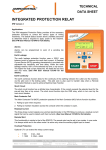
MPAB001 R8, CRN 8950, 29/11/2011 MPA3 V5.4 Motor Protection Relay for General Industrial Applications 1. Description The Ampcontrol MPA Motor Protection Relay has been designed for use in an industrial environment, to provide optimum overload protection of small to medium sized 415V motors used on conveyors, pumps, fans and compressors. It can also be used with higher voltage motors. In addition to motor protection, the relay has features to monitor temperature, provide alarms before a trip condition and through a 50 record event log, allows diagnosis of a problem after a fault has occurred. An optional insulation test module (MPA-I) allows frequent testing of motor insulation. The standard current transformers supplied with the MPA Protection Relay enable protection of motors with full load currents ranging from 5.125 A to 640 A. The selected full load current can be set to one of 224 values across the range. The settings prefixed by A automatically reset a motor overload trip once the thermal accumulator falls below the set value. Otherwise the trip has to be reset manually by pressing the keypad ‘RESET’ button or activating the ‘RESET’ digital input once the thermal accumulator has fallen below the set value. The MPA Motor Protection Relay has 5 digital inputs, which feed into a microprocessor unit. The microprocessor has been programmed to control three output relays: MTR (Main Trip Relay), ALM (Alarm Relay) and AUX (Auxiliary Relay). Inputs are also provided for PTC Thermistors and current transformers. A two-line backlit LCD display combined with a keypad provides an easy to operate user interface. The display provides easy access to all available information. A simple procedure allows adjustment of the relay’s settings. An optional Energy Storage Module allows the MPA Relay to function normally for a period of two (2) seconds during an extreme power dip or power loss. An optional monitoring module (MPA-M) can be utilised to provide the following features: Five PT-100 RTD inputs, which are arranged in two groups, three for the stator and two for the bearings. RS485 Modbus RTU communication port that can be connected to Motor Starter PLC's or a central monitoring system for continuous monitoring and fault-finding. A 0-20 mA / 4-20 mA Analogue Output. Alternatively, optional monitoring module MPA-M (e) may be used to provide the same features as those of optional monitoring module MPA-M except the RS485 Modbus communication port is replaced by an Ethernet IP communications port. Earth Leakage Motor Contactor Fail Phase Current Unbalance Undercurrent/Over-current Alarms Over Temperature - PTC Thermistor Optional Under-voltage Optional Insulation Test Optional PT-100 RTD Temperature Protection 3. Features Twenty three status messages Record of last 50 events Automatic or manual reset of motor overload Real time clock Display of Current, Temperature, Earth Leakage Current, Voltage, Overload Accumulator. Message Display to assist fault finding Optional Energy Storage Module Optional RS485 communication port interfaces to SCADA system via Modbus protocol. Optional EtherNet/IP communication port interface Optional analogue output 0-20 mA/4-20 mA 4. Application The MPA Motor Protection Relay requires three current transformers to measure the three line currents. The measured currents are used to implement the following protection functions: a) Overload The MPA is housed in an enclosure suitable for flush mounting in a 135mm square cut out and has robust plug in connectors on the rear. b) Short Circuit See MPA User Manual 143402 for full details. d) Residual Current 2. Protection Functions The Ampcontrol MPA motor Protection Relay provides protection functions for: Overload Short Circuit (Continued next column) c) Phase Current Balance Specifications: The motor overload function is based on calculations within the MPA’s microprocessor, which simulates the motors thermal behaviour. The measured current signals provide the 'I2R' heating input to the simulation. The output of the simulation is the 'Thermal Accumulator'. A motor overload trip occurs when this value reaches 100%. The accumulator represents the simulated motor temperature. The trip time is a function of the current and the selected trip time curve. The fifteen (15) motor overload curves provide trip settings from 3 to 40 seconds. The three phase current signals are summed electronically in the relay to produce a residual current signal that can be used to detect earth fault currents. This feature is selectable and can be used in conjunction with the core balance earth leakage protection provided by the relay. Short Circuit (S/C) The short circuit function has a definite time characteristic. If the current exceeds the selected level for the pre-set time then a trip occurs. The short circuit function trips the auxiliary relay. (The AUX relay is normally energised, and drops out when tripped). The short circuit trip level is selected as a multiple of the selected full load current, from 3.0 to 10 times FLC, in steps of 0.5. A new “Off” option has been added to the S/C selections. This allows the use of external S/C protection methods. Phase Current Balance Phase current balance protection is selectable at 5%, 10%, 20%, 50% and off. The phase current balance protection is inhibited until the average current exceeds both 20% of the selected full load current and the selected balance trip level. Auxiliary Supply Volts: 240 VAC 20%, 50 Hz 2Hz 110 VAC ± 20%, 50 Hz ± 2 Hz Earth Leakage Protection: Trip Setting: 100-500 mA and ‘OFF’ (with approved 100:1 Toroid) Time Delay: 155 ms – 475 ms Residual Current: Trip Setting: 10% - 100% FLC and Off Time Delay: 100 ms – 5 Sec Overload Protection: Current Range: 5.125 A – 640 A (In 224 values across the range. Steps 1.6% - 3%) 6 x I Trip Time: 3,4,5,6,7, 8,10,12,14,16,20,24,28,32 & 40 Seconds S-Cool Ratio: 1.0, 1.5, 2.0, 2.5, 3.0, 4.0, 5.0 O/L Reset Level: 30%, 40%, 50%, 60%, 70%, 80% 90% Current Balance: Trip Settings: 5%, 10%, 20%, 50% and Off Short Circuit Protection: Trip Setting: 3.0x to 10.0x FLC 0.5 increments and Off. Trip Time: 20, 40, 60, 80, 100, 120, 160 ms Under-voltage Protection: Trip Setting: Selectable from 40% to 95% and Off Trip Delay: 1.5 Sec Insulation Test: Selectable from 1.0 to 100 Meg.ohm and Off RTD Temperature Protection: Trip: Selectable from 60C to 200C and Off. Time Delay: 2 Sec Insulation Test MPA Standard Alarms: The optional MPA-I Module allows the insulation resistance of 415 V motors and/or installations to be tested with 500 VDC to earth. A selectable threshold allows an alarm to be triggered if the resistance to earth is too low. This test can only be performed when the motor is not running. An external ‘Insulation Test Enable’ must also be closed to allow a test to be performed. A test is activated by closure of the digital input (DI1). The test takes 3 seconds. At the end of the test, the measured resistance is compared to the selected threshold. If the result is below this level an alarm will be triggered. The measurement range goes up to 120 MΩ. The trip and alarm thresholds are selectable in the range 1.0 to 100 MΩ. High Current: Selectable from 100% to 600% and Off. Time Delay: 1 Sec Overload: Selectable from 50% to 95% and Off. Time Delay: 2 Sec Under Current: Selectable from 32% to 96% and ‘Off’. Time Delay: 2 Sec Earth Leakage: 20%, 50% and 80%. Time Delay: 1Sec Serial Communications: Two different optional monitoring modules are available providing the user with a choice of RS485 Modbus RTU or EtherNet/IP Dimensions (mm): Escutcheon: 155 x 155 Case: 132 W x 132 H x 113 D Cut out: 135 x 135 Relay Contacts: MTR: 1 N/O 5A/250 VAC, 1 C/O 5A/250 VAC ALM, AUX: 1 N/O 5 A/250 VAC Base Models and Options Part Numbers Auxiliary Extended Supply Service Voltage Motor MPA3V06.2 Std/ 110 110 MPA3V06.2 I/ 110 MODEL DESCRIPTION Optional Monitoring Modules Serial Communications Option PART NUMBER Insulation Test Over-Temp Ethernet/ IP RS485 Modbus X X X X X 120366 110 X YES X X YES 120368 MPA3V06.2 M/ 110 110 X X YES X YES 120369 MPA3V06.2 IM/ 110 110 X YES YES X YES 120371 MPA3V06.2 IM(e)/ 110 110 X YES YES YES X 143095 MPA3V06.2 IM(e)/ 240 240 X YES YES YES X 143096 Auxiliary Extended Supply Service Voltage Motor MPA3V05.2 Std/ 110 110 MPA3V05.2 Std/ 240 MODEL DESCRIPTION Optional Monitoring Modules Serial Communications Option PART NUMBER Insulation Test Over-Temp Ethernet/ IP RS485 Modbus X X X X X 120405 240 X X X X X 120228 MPA3V05.2 Std/ E240 240 YES X X X X 120367 MPA3V05.2 I/ 110 110 X YES X X YES 120224 MPA3V05.2 M/ 110 110 X X YES X YES 120404 MPA3V05.2 M/ 240 240 X X YES X YES 120229 MPA3V05.2 M/ E240 240 YES X YES X YES 120370 MPA3V05.2 IM/ 110 110 X YES YES X YES 120403 MPA3V05.2 IM/ 240 240 X YES YES X YES 120230 MPA3V05.2 IM/ E110 110 YES YES YES X YES 121529 MPA3V05.2 IM/ E240 240 YES YES YES X YES 120372 MPA3V05.2 IM(e)/ 110 110 X YES YES YES YES 143093 MPA3V05.2 IM(e)/ 240 240 X YES YES YES YES 143094 101272 XXXXXX 1000/1 45mm ID Current Transformers (3 Required) Earth leakage Toroid to be specified at time of order