1
•
Internal Temp:
Latest:
•
xV
xV
Trig. Voltage
Latest: x V
-Limit: x V
The line voltage of the power
source
The most recent measurement
The lower programmed limit
allowed
The trigger voltage
The most recent measurement
The lower programmed limit
allowed
•
Bank Voltage:
Latest: x V
-Limit: x V
The capacitor bank voltage
The most recent measurement
The lower programmed limit
allowed
•
Day Energy:
A measurement of the flash energy
in day mode. Limit can be set from
the Service Menu.
The most recent measurement
The lower programmed limit
allowed
Latest:
-Limit:
•
•
•
•
5-4
Actual:
x
Missed: x
Line Voltage:
Latest:
-Limit:
•
The internal temperature of the
power converter or beacon
x deg C
The most recent measurement
xV
xV
Twi Energy:
+Limit:
xV
Latest:
-Limit:
xV
xV
Night Energy:
+Limit:
xV
Latest:
-Limit:
xV
xV
Red Energy:
+Limit:
xV
Latest:
-Limit:
xV
xV
Mode Flashes:
A measurement of the flash energy
in twilight mode.
The upper programmed limit
allowed
The most recent measurement
The lower programmed limit
allowed
A measurement of the flash energy
in white night mode.
The upper programmed limit
allowed
The most recent measurement
The lower programmed limit
allowed
•
Mode Triggers:
Actual: x
Missed: x
rent operating mode
The actual number of flash
attempts
The number of missed flashes
The number of times the trigger has
operated in the current mode
The number of actual triggers
The number of missed triggers
•
Marker Voltage: The socket voltage of the marker
bulbs
Latest: x
The most recent measurement
•
# Marker Bulbs: The number of marker bulbs currently operating
Latest: x
The number operating now
-Limit: x
The lower limit alarm threshold of this tier.
•
Firmware:
The version number of the main
circuit board in the controller.
2-4990-xx v0.0
Button Functions in the Diagnostic Screens
• Within a Diagnostics screen, the ENTER Button
shifts the cursor between the function name and the
beacon number.
• When the cursor is on the function name, the UP and
DOWN Buttons scroll from one function to the next
or previous function for a given beacon.
• When the cursor is on the beacon number, the UP and
DOWN Buttons scroll from one beacon to the next or
previous beacon for a given function. (This arrangement allows you to compare all beacons for a particular function, or to examine all functions for a
particular beacon.)
• EXIT returns the screen to the menu.
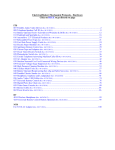
Figures 5-4 to 5-21 are examples of Diagnostic screens.
A measurement of the flash energy
in red night mode.
The upper programmed limit
allowed
The most recent measurement
The lower programmed limit
allowed
The number of flashes in the curRevision 2 — 6-24-2003
NOTE
When you enter Diagnostics from the
menu, the system returns immediately
to the last Diagnostic screen shown during the previous Diagnostics access,
even if you have logged off. This is convenient if you regularly monitor a particular function or beacon. However, be
aware that your scrolling may not be
starting at the top of the list for either
beacons or functions.
FTC 121-2