1
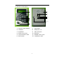
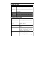
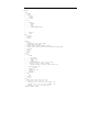
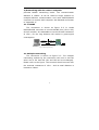
Appendix A Port and extended signal
JP2
1
JP3
4
1
1
10
1 3
12
JP4
JP5
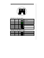
Description for JP1 port signal
Terminal Signal
Color
1
+V
red
2
3
4
5
6
7
8
9
10
GND
MC1
OP1
MC2
OP2
LS1
LS1
LS2
LS2
4
black
green
yellow
white
brown
blue
purple
orange
gray
JP1
Remark
Positive power terminal
(+12DCV)
Power ground
Sensor 1
Button 1
Sensor 2
Button 2
Relay output 1
Relay output 2
Description for JP2, JP3 port signal
Terminal Signal
Color
Remark
1
+V
red
Positive power terminal
2
GND
black
Power ground
3
DATA0
green
W26 data line
4
DATA1
yellow
W26 data line
21