1
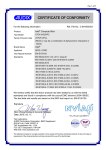
TVOC User Manual V2.6
GasTech Australia Pty Ltd
24 Baretta Rd
Wangara Western Australia 6065
Tel 1800 999 902
Fax 1800 999 903
http://www.gastech.com.au
TVOC MANUA L
GasTech Australia
Page 2 of 32
DECLARATION OF CONFORMITY
Manufacturer: Ion Science Ltd, The Way, Fowlmere, Cambridge, SG8 7UJ, UK
Product:
T VOC
Product Description: An intrinsically safe fixed continuous monitor comprising of a photo-ionisation
detector for detecting and measuring volatile organic compounds with a 4-20mA
output
Directive 94/9/EC
Identification:
Notified Body:
ATEX
II 2G Ex ia I IC T4 (-20o C ≤ Ta ≤ +50o C)
Baseefa Ltd, 1180, Buxton, UK
EC Type Examination Certificate(s)
Baseefa05ATEX0277
latest supplement Baseefa03ATEX742/2 issued 24 th November 2008
IECEx BAS 06.0057
latest revision no.1 issued 20 th November 2008
Standards
BS EN 60079-0:2006
Electrical Apparatus for Potentially Explosive Atmospheres – General Requirement
BS EN 60079-11:2007 Explosive Atmospheres - Equipment Protection by Intrinsic Safety ‘i’
BS EN 61010-1:2001
Safety requirements for electrical equipment for measurement, control and
laboratory use – General requirements
Directive 2004/108EC Electrical Equipment – Electromagnetic Compatibility (EMC)
BS EN 50270:1999
Electromagnetic compatibility. Electrical apparatus for the detection and
measurement of combustible gases, toxic gases or oxygen
BS EN 61000-6-6:2001 Electromagnetic Compatibility (EMC) Generic standards. Emission standard for
residential, commercial and light industrial environments
With respect to BS EN 50270: 1999, the TVOC achieves perf ormance criteria A (the apparat us continues to operate as
intended bef ore and after the test) except at spot frequenc ies where it achiev es criteria B (the apparatus continues to
perf orm after the test but during the test a degradat ion of perf ormance is seen). See technical specif ication f or details.
Other Standards
BS EN ISO 9001:2000 Quality Management Systems – Requirements
BS EN 13980:2002
Potentially Explosive Atmospheres – Application of Quality Systems
On behalf of Ion Science Ltd, I declare that, on the date this product accompanied by this declaration is
placed on the market, the product conforms to all technical and regulatory requirements of the above listed
directives.
Name: Mark Stockdale
Position: Technical Director
Signature:
Date: 20th November 2008
TVOC MANUA L
GasTech Australia
Contents
1
2
3
4
Page
– Statements
.
.
.
.
– Introduction to TVOC
.
.
.
– Packing List
.
.
.
.
– TVOC Set up
.
.
.
.
Selector pins .
.
.
.
Cy cle times
.
.
.
.
5 – Installation
.
.
.
.
Location
.
.
.
.
Mounting
.
.
.
.
Cable requirements
.
.
.
Power requirements
.
.
.
Non Intrinsically Safe (IS) applications
Intrinsically Safe (IS) applications.
Initial calibration
.
.
6 – Operation .
.
.
.
.
Start up .
.
.
.
.
Cy cle times
.
.
.
.
LED’s .
.
.
.
.
Selector pins .
.
.
.
Calibration mode
.
.
.
7 – Calibration
.
.
.
.
Calibration routine
.
.
.
Setting the zero .
.
.
.
Setting the gas tolerance
.
.
Setting the span
.
.
.
Display lamp life
.
.
.
8 – Maintenance
.
.
.
.
Cleaning and replacing the PID lamp
.
Fuse rupture and replacement .
.
Lamp warranty statement
.
.
9 – Diagnostics
.
.
.
.
10 – Spare parts
.
.
.
.
11 – Technical Specifications
.
.
.
.
.
.
.
.
.
.
.
.
.
.
.
.
.
.
.
.
.
.
.
.
.
.
.
.
.
.
.
.
.
.
.
Page 4 of 32
.
.
.
.
.
.
.
.
.
.
.
.
.
.
.
.
.
.
.
.
.
.
.
.
.
.
.
.
.
.
.
.
.
5
6
7
8
8
9
10
10
11
12
12
12
14
16
17
17
17
18
18
19
20
20
21
22
22
23
24
24
27
27
28
30
31
TVOC MANUA L
1
GasTech Australia
Statements
Responsibility for use
TVOC detects a large range of gases, which are potentially dangerous from both a poisoning and/or an
explosiv e perspectiv e. TVOC has a number of selectable features allowing the detector to be used in a
v ariety of applications. Ion Science Ltd can accept no responsibility for the incorrect adjustment of features
that cause harm or damage to persons or property . It is the users’ responsibility to respond appropriately to
the readings deliv ered.
!Warning!
1. Substitution of components may impair intrinsic safety and result in unsafe conditions.
2. For reasons of safety , TVOC must only be operated and serv iced by qualified personnel.
3. Please read and understand this user manual fully before installing, operating or serv icing TVOC.
Quality assurance
TVOC has been manufactured in compliance with ISO9001:2000, which ensures that the equipment supplied
to our customers has been designed and assembled reproducibly , from traceable components, and leav es
Ion Science calibrated to stated standards.
Disposal
Dispose of TVOC and its components in accordance with all local and national safety and env ironmental
requirements. This includes the European WEEE (Waste Electrical and Electronic Equipment) directiv e. Ion
Science Ltd offers a tak e back serv ice. Please contact us for more information.
Contact Ion Science Ltd
By Post
Ion Science Ltd
The Way
Fowlmere
Cambridge
SG8 7UJ
UK
By Telephone
By Fax
By Email
+44 ( 0) 1763 208503
+44 ( 0) 1763 208814
[email protected]
Distributed By
106 Westpoint Centre
396 Scarborough Beach Road
Telephone 1800 999 902
Facsimile 1800 999 903
http://www.gastech.com.au
Page 5 of 32
TVOC MANUA L
2
GasTech Australia
Introduction to TVOC
TVOC is a fixed continuous monitor for the detection and measurement of total volatile organic compounds,
which can be dangerous from both a poisonin g and explosiv e perspectiv e. Total VOC’s are detected using
PID (Photoionisation Detection) technology ).
TVOC has a number of user selectable features which define its operation and will be application dependent.
The user can define the detection ranges or 0.01 - 10ppm, 0.1 – 100 ppm or 1 – 1,000 ppm (Default);
detection units, either ppm or mg/m3; and the duty cy cle time i.e. the frequency that the instrument tak es a
measurement. Duty cy cles are explained in more detail in section 4, TVOC set up, and section 6 Operation.
IMPORTA NT: if the 10ppm range is selected the TVO C will requir e a calibration using 10ppm Isobuty lene
before use.
The default settings of TVOC are:
Detection range
–
Units
Duty cy cle
-
0.1 – 1000 ppm
ppm
5 seconds ON / 55 seconds OFF
TVOC giv es a continuous 4 – 20 mA output which can be integrated into a DCS control sy stem to giv e an
indication of VOC lev els in the operating env ironment.
In addition to the 4 – 20 mA output TVOC has an LCD display showing gas concentration and 4 colour LED’s.
LED functions are as follows:
Green
- is an indicator of TVOC’s work ing status
Red
- is the fault indicator
Yellow x 2
- are calibration status indicators
Please see section 7 Calibration for more information on LED status.
For installation requirements please refer to sections 5 and 10 of this manual. For Intrinsically Safe (IS)
installations please also refer to the TVO C A TEX certificate for further details. Before attempting an
installation, please fully read and understand this user manual.
TVOC does require regular calibration onsite please see section 7 Calibration for information. TVOC
calibration mode is accessed v ia a magnetic read switch sy stem.
The TVOC intrinsic safety rating permits its deploy ment in all hazardous areas of the quoted (or less
demanding) rating. That is, in areas where explosiv e gases (of Group IIA , IIB and IIC) are intermittently
present (Zone 1) within an ambient temperature range of -20°C and +60°C.
Page 6 of 32
TVOC MANUA L
3
GasTech Australia
Packing List
A ll items of equipment shipped by Ion Science Ltd are pack ed in suitable containers and enclosed in a shock
absorbing filling which affords a considerable degree of protection against phy sical damage.
Contents should be carefully remov ed and check ed against the pack ing list. A ny discrepancies between the
contents and the pack in g list must be reported to Ion Science Ltd within 10 day s of receipt of shipment. Ion
Science cannot be held responsible for shortages not reported with in the perio d.
Standard TVOC instrument
Item
Description
Qty
1.
2.
1
1
TVOC instrument
TVOC Manual
TVOC Calibration Tool Kit
Item
Description
Qty
1.
2.
3.
4.
5.
6.
1
1
1
1
1
1
Calibration magnet
Calibration adaptor
Calibration connector
A spirator
Carbon filter
A llen k ey s
3. Calibration
Connector
2. Calibration
Adaptor
1. Calibration
Magnet
6. A llen Key s X 2
5. Carbon
Filter
4. A spirator
Page 7 of 32
TVOC MANUA L
4
GasTech Australia
TVOC Setup
4.1 Selector Pins
TVOC has a number of settings that can be selected by the user
v ia a row of 4 selector pins mounted on the rev erse side of the
main PCB. Diagram 4.1 shows the location of the functional
selector pins labelled - A , B, C & D.
The selector pins absence or presence determines the chosen
setting.
Diagram 4.1
Diagram 4.1
TVOC is shipped with all 4 selector pins fitted as shown in
diagram 4.2.
Diagram 4.2
Diagram 4.3 demonstrates the remov al of 1 selector pin.
Diagram 4.3
Page 8 of 32
TVOC MANUA L
4
GasTech Australia
TVOC Setup
The following table shows the selector pin combinations and the corresponding function.
a= Selector pin fitted
r = Selector pin remov ed
A
a(n/a)
a(n/a)
a(n/a)
a(n/a)
a(n/a)
a(n/a)
Selector pin
B
C
a
a
a
x
x
a
a
a
a
x
x
a
D
a
a
a
x
x
x
Selector pin ‘B’ and ‘C’ selects the ranges
Selector pin ‘D’ selects the units
Selector pin ‘A ’
Range
1000
100
10
2280
228
22.8
-
Display ed units
ppm
(Default)
ppm
ppm
mg/m3
mg/m3
mg/m3
10ppm, 100ppm or 1,000ppm
ppm’ or ‘mg/m3
Currently not used
IMPORTA NT: if the 10ppm range is selected the TVO C will requir e a calibration using 10ppm Isobuty lene
before use. (See the calibration section of this manual)
NOTE:
* TVOC is shipped with all selector pins fitted as standard
* TVOC only reads the selector pin settings when power is connected.
A lway s ensure power is disconnected from TVOC before changing
setting or carry in g out maintenance.
* Nev er place selector pins on the programming port connector.
* Ensure static build up is discharged before touching components.
4.2 Duty Cycle
The TVOC has a v ariable duty cycle whereby the lamp is ON for 5 seconds and then OFF for a user set
period between 0 to 5 minutes in 1 second increments. The 4 – 20 mA output is updated at the end of each
cycle. A s standard the TVOC duty cycle is 1 minute – the lamp is ON for 5 seconds and OFF for 55 seconds.
The lamp OFF time is fully adjustable by the user. Please see section 6.1 of this manual for full instructions.
Page 9 of 32
TVOC MANUA L
5
GasTech Australia
Installation
5.1 Location
There are many v ariables inv olv ed in defining the optimum location for a gas detector. Obv ious though it
may sound, the most important rule is:
·
A detector will not detect gas unless gas actually reaches the detector.
TVOC should be mounted in the location most lik ely to detect gas.
·
·
·
·
·
·
·
TVOC must be mounted v ertically with the sensor underneath the case. This av oids dust and debris
block ing the access to the detector cell.
Mount TVOC higher if detecting VOC gases that are lighter than air or lower if detecting VOC gases
that are heav ier than air (but nev er on the floor). This should maximise detection.
Mount TVOC in an area that has good air circulation. Restricting natural air current may result in
delay ed detection.
Nev er mount TVOC in direct sunlight or ov er a heat source such as a radiator. This may cause TVOC to
exceed its certified work ing range.
Do not mount TVOC where it’s subjected to rain fall, water, aerosols, mist or heavy condensation.
Mount TVOC in areas that are easily accessible for serv icing.
Percentage v ariations in the composition of air (78% Nitrogen, 21% Oxy gen and 1% Argon) may
affect the detected signal.
Please refer to the technical spe cifications of the instrument i n Section 10 of this manual before
beginning a TVOC installation.
Page 10 of 32
TVOC MANUA L
5
GasTech Australia
Installation
5.2 Mounting
Dimensions for mounting TVOC are giv en in Diagram 5.2.1 below.
Diagram 5.2.1
NOTE:
The TVOC case can be used as a template when mark ing out fixing holes but do not drill
through the fixing holes.
Page 11 of 32
TVOC MANUA L
5
GasTech Australia
Installation
5.3 Cable requirements
Ion Science Ltd suggests using screened cables for both power in and signal out. Cable screens must
be terminated at the TVO C enclosure using EMC cable glands.
5.4 Power requirements
5.4.1 Non Intrin sically Safe (Non IS) applications:
Input power
5 - 28Vdc. 65mA max.
4-20mA power
8-35Vdc. 22mA
4 Wire Sy stem
Diagram 5.4.1
3 Wire Sy stem (a)
Page 12 of 32
TVOC MANUA L
5
GasTech Australia
Installation
3 Wire Sy stem (b)
!WARNING!
Non Intrinsically Safe (Non IS) applications
When the unit is installed with a non IS rated power supply the IS details on the front of the unit are not
appropriate for the sy stem. The IS label should be cov ered up or block ed out. This will prev ent safety
discrepancies and or mis-use in the future should the equipment be mov ed or the site be re-defined as a
hazardous area.
Page 13 of 32
TVOC MANUA L
5
GasTech Australia
Installation
5.4.2 Intrinsically Safe (IS) applications: Entry parameters
Input power
Ui = 18V
Ii = 800mA
Pi = 1.2W
4-20mA power
Ui = 30V
Ii = 200mA
Pi = 1.2W
For information only please see A TEX certificate before installation
Ci = 0mF
Ci = 0mF
Li = 0mH
Li = 0mH
Ion Science Ltd suggest using the following Zener Barriers for IS approv ed applications. Use competent
installation engineers and ask them for installation and application adv ice.
POWER SUPPLY: Suggested barriers for INLET power supply
Manufacturer
Manufacturers pt no.
Type
Pepperl+Fuchs
Z715
Zener barrier
Pepperl+Fuchs
KFD2-SD2-EX1.1065
Galv anic isolator
MTL
7715P+
Zener barrier
Stahl
9901/01-158-270-101
Zener barrier
Stahl
9143/10-156-065-10
Galv anic isolator
Cable length estimate
~ 1115 meters
~ 1217 meters
~ 772 meters
~ 500 meters
SIGNA L OUTPUT: Suggested barriers for 4-20mA OUTLET
Manufacturer
Manufacturers pt no.
Type
Pepperl+Fuchs
Z728
Zener barrier
Pepperl+Fuchs
KFD2STC4-Ex1
Galv anic isolator
MTL
MTL7787
Zener barrier
MTL
MTL5042
Galv anic isolator
Stahl
9001/01-280-110-141
Zener barrier
Stahl
9160/13-11-11
Galv anic isolator
NOTE
· A ll cable lengths are estimated for zone 1 IIC installation of the equipment
· Using 1mm2 C.S.A conductor S.T.P cables with capacitance per meter of 250pF/m, L/R ratio of
25uH/W conductor resistance at 20°C of 18.4W /k m.
· Calculation assumes cables are at 50°C.
WARNING!
Intrinsically Safe (IS) applications
· Units should not be powered using non IS power supplies prior to installation in an IS application.
· If non IS power is supplied the unit will require inspection by Ion Science Ltd or an Ion Science
·
·
A pprov ed Serv ice Centre prior to installation in an IS application.
TVOC fuses may not be replaced in the field.
If a fuse is blown TVOC will require inspection by Ion Science Ltd or and Ion Science A pprov ed Serv ice
Centre before it is used in an IS application.
Page 14 of 32
TVOC MANUA L
GasTech Australia
5 Installation
Diagram 5.4.2.1 Control equipment sensing 4 – 20 mA at supply rail
Diagram 5.4.2.2 Control equipment sensing 4 – 20 mA to 0V
Diagram 5.4.2.3 Control equipment sensing (3 wire)
Page 15 of 32
TVOC MANUA L
5
GasTech Australia
Installation
5.5 Initial calibration
TVOC is calibrated at Ion Science before dispatch using 100ppm Isobuty lene. Howev er if y ou wish to
calibrate y our TVOC once it is installed Ion Science recommends that the TVOC is left to run on its chosen
settings (see Section 4 TVO C Set up) for 24 hours before an initial calibration is carried out, to allow the
instrument to settle into the work ing env ironment.
Page 16 of 32
TVOC MANUA L
6
GasTech Australia
Operation
6.1 Start Up
A fter electrical power is connected, TVOC runs through a ‘Start up’ routine, which lasts for approximately 1
minute. During this ‘Start up’ routine TVOC demonstrates the following characteristics:
* The LCD screen display s the software v ersion number
* The GREEN LED flashes
* The 4 – 20 mA output is set to 4 mA (0.0 ppm)
NOTE: I the 0-10ppm range is selected the TVO C will require calibration using 10ppm Isobuty lene before
user (See the calibration section of this manual)
During this ‘Start-up’ time the user can adjust the lamp OFF time as referred to in Section 4.2. This time can
be adjusted from 0 to 5 minutes in 1 second increments.
6.2 Cycle times
To extend PID lamp life and the time between serv icing, TVOC includes a
v ariable duty cy cle, (see section 4.2) whereby the lamp is switched ON
and OFF. The length of time between serv icing and calibration is
increased where longer OFF times are selected. Howev er the length of
time between serv icing also depend on ambient air quality , the higher
VOC concentration detected by the instrument then the shorter the time
between serv icing.
6.2.1 A djusting the lamp OFF time
There are two stages to adjusting the lamp OFF time. The first stage adjusts the seconds (0-59) and the
second stage adjusts the minutes (0-5). To adjust the lamp OFF time the magnetic switch must be activ ated
during the ‘Start-up’ time.
NOTE: Please read this entire procedure before attempting to adjust the lamp OFF time.
1 – During the 1 minute ‘Start up’ routine place the calibration magnet ov er the top
right hand corner of the Ion Science logo. Two numbers on the LCD screen will flash.
2 - This indicates the lamp OFF time in seconds.
3 – Placing the calibration magnet back ov er the logo will cause the number to role between 0 and 59
seconds. Remov e the magnet when the desired time is display ed.
4 – A fter 5 seconds the display will show another two numbers and flash.
5 – This indicates the lamp OFF time in minutes.
6 – A gain place the calibration magnet ov er the logo to rotate the numbers between 0
and 5 minutes. Remov e the magnet when the desired time is display ed.
Page 17 of 32
TVOC MANUA L
6
GasTech Australia
Operation
7 - A fter 5 seconds the entire output frequency is display ed.
8 - A fter a further 5 seconds the set frequency will be set in the
TVO C memory .
9 - TVOC then continues through the standard start-up routine.
If y ou are unhappy with the update frequency you hav e set y ou can adjust the time by placing the
calibration magnet ov er the logo during the 5 seconds after the total time has been shown (point 8 abov e).
NOTE: The total duty cy cle time includes the 5 seconds lamp ON time. Therefore if y ou wish your total duty
time to be approximately 2 minutes set the lamp OFF time to 1 minute 55 seconds.
A t the end of the ‘Start up’ routine TVOC will enter the selected monitoring routine.
6.3 LED’s
The GREEN LED indic ates TVO C’s work ing status
ON
Indicates the PID lamp is OFF
Flashing
Indicates the PID lamp is ON
The RED LED indicates Fault status
ON
Flashing
Indicates TVOC cannot function correctly . The 4-20mA output drops
to 3.5mA .
URGENT attention is required.
Indicates the last calibration carried out was outside expected
limits. The instrument will continue work ing but serv ice is required.
Please see Section 7 Calibration for YELLOW LED status.
6.4 Selector pins
TVOC has a range of options that are selected v ia the selector pins on the back of the main PCB (please see
Section 4 TVOC Set up).
The options are shown below with the defaults highlighted in bold:
1-1000ppm
or
0.01 - 10 ppm or 0.1 - 100 ppm
ppm units
or
mg/m3 units
Page 18 of 32
TVOC MANUA L
6
GasTech Australia
Operation
6.5 Calibration mode
TVOC calibration mode can be accessed using the calibration
magnet supplied in the TVOC calibration tool k it (Part number:
A -845214).
To enter calibration place the magnet ov er the top right of the
Ion Science Logo until the state changes (i.e. an LED illuminates
and/or the display changes).
Ensure the magnet is withdrawn away from the magnetic switch
by at least 1 cm once a change has occurred.
6.6 Calibration gases
TVOC has three (3) ranges that can be selected howev er the 0-10ppm range requires the instrument is
calibrated by the user before use. The 0-100ppm and the 0-1000ppm ranges can initially run using the
Factory calibration carried out durin g the instruments manufacture, howev er because the 0-10 ppm range is
more sensitiv e and more susceptible to env ironmental and sy stem tolerances the instrument must be
calibrated using 10ppm Isobuty lene before use.
If the 0-10 ppm range is selected TVOC will display the followin g
screen to indicate that a calibration is required before it can be used.
Follow the calibration instructions before use.
Page 19 of 32
TVOC MANUA L
7
GasTech Australia
Calibration
7.1 Calibration routine
Ion Science recommends calibrating TVOC after any maintenance or lamp cleaning is carried out and on a 3
monthly basis to ensure TVOC is work ing to specification.
NOTE: Please read this entire calibration procedure before attempting a calibration.
TVOC calibration has 4 stages:
1. Setting the ZERO
2. Setting the gas tolerance
3. Setting the SPA N
(Using clean gas v ia carbon filter)
(90 – 110 ppm Isobuty lene on 0-100 ppm and 0-1000 ppm ranges)
(9 - 11ppm Isobuty lene on the 0-10ppm range)
(Using the SPAN gas)
GREEN
STATUS LED
ZERO LED
SPA N LED
FA ULT LED
Page 20 of 32
TVOC MANUA L
GasTech Australia
7 - Calibration
7.2 Setting the ZERO
1–
Place the calibration magnet ov er the top right hand corner of the Ion Science logo to enter
calibration mode. The ZERO LED will illuminate and the GREEN STA TUS LED will extinguish.
2–
Remov e the calibration magnet
3–
Insert the calibration adaptor into the sensor cap, attach the carbon filter to the calibration
adaptor. The carbon filter should be attached to the hand aspirator.
4–
A gain place the calibration magnet ov er the logo. The ZERO LED will flash, during this stage TVOC
display s a direct miliv olt (mV) output from the PID sensor.
Cali brati on adaptor
56–
Carbon fi lter
Hand
aspi rator
Slowly and repeatedly squeeze the hand aspirator to push clean air through the carbon filter and
past the PID sensor. The ZERO LED will stop flashing after approximately 2 minutes.
Now remov e the equipment except for the calibration adaptor.
NB During the Zeroing process the mV reading on the display must reduce to belo w 30 mV to pass the ZERO
calibration stage.
A n acceptable ZERO calibration lev el will result in the illumination of the GREEN LED.
A n unacceptable ZERO calibration lev el will result in the illumination of the RED LED. Should
the previous zero calibration level will be used.
Page 21 of 32
this occur
TVOC MANUA L
7
GasTech Australia
Calibration
7.3 Setting the gas tolerance
1–
Now, again place the calibration magnet ov er the corner of the logo The GREEN or RED LED will be extinguished and the numeric display
will start to flash.
2If the 0-10ppm range is selected y ou will be able to adjust between 9.0 ppm and 11.0ppm, for both
the 100 ppm and 1000 ppm ranges a tolerance of between 90 and 100 ppm can be selected.
Leav ing the magnet in position will cause the display ed number to count through the tolerance,
remov e the magnet when the display ed v alue matches that stated on the Calibration gas bottle.
Should y ou miss the desired reading quick ly reapply the magnet to continue scrolling through the
numbers and remov e the magnet at the desired figure.
The selected number will be recorded 5 seconds after the remov al of the magnet when the display
stops flashing. The display will initially show 100, should this be the desired figure remov e the
magnet straight away .
7.4 Setting the SPA N
1Connect the SPAN gas to the calibration connector then the connector to the adaptor. Do not ov er
tighten the Luer fitting; only a ¼ turn is required.
Switch on the gas supply and then place the magnet ov er the logo.
The SPAN LED will flash and TVOC will display the direct milliv olt (mV) output from the PID sensor.
Now remov e the magnet.
Calibration adaptor
SPA N gas
Calibration connector
23–
The SPA N LED will stop flashing after approximately 2 minutes.
Turn off the gas and disconnect the equipment
NB During the SPA N the display ed mV reading must reach at least 80 mV to pass the SPA N calibration
stage.
Page 22 of 32
TVOC MANUA L
7
GasTech Australia
Calibration
A n acceptable SPA N calibration lev el will result in the illumination of the GREEN LED.
A n unacceptable SPA N calibration lev el will result in the illumination of the RED LED. Should this occur the
prev ious span calibration lev el will be used.
Now place the magnet ov er the logo corner to return to normal monitoring routine.
The GREEN LED will start flashing as TVO C starts its cy cle with a lamp ON cycle.
If either the ZERO and/or SPA N lev els where outside acceptable lev els the RED LED will flash until an
acceptable calibration has been carried out.
Unacceptable calibration lev els will NOT be used, TVOC will default to the prev iously stored acceptable
calibration factor.
NOTE:
*
A lway s check the accuracy of y our calibration by check ing readings from TVOC when it is running
normally using the ZERO filter and SPA N gas.
*
A ccuracy of calibration is the responsibility of the person carry ing out the calibration. If in doubt seek
adv ice.
*
TVOC must be calibrated after lamp/cell cleaning or general maintenance.
NOTE: Causes of contamination and error in signal:
*
Changes in air pressure when detecting ppm concentration
*
Variation in Oxy gen and / or A rgon bey ond ambient lev els.
*
Variation in ambient moisture content.
Page 23 of 32
TVOC MANUA L
8
GasTech Australia
Maintenance
Cleaning / replacing the la mp
TVOC has been designed to ensure serv icing is quick and easy:
1. Before serv icing TVOC,
disconnect the electrical
power supply .
2.Remov e the Lock ing Screw
from the Metal Sensor Cap
using the A llen Key
supplied within the
Calibration tool k it.
(Calibration tool k it part number
A -849214)
WARNING:
Failing to remov e the lo ck ing
screw before unscrewing the
Sensor Cap will damage the
sensor holder.
3. Unscrew the sensor Cap
to access the PID sensor.
Lock ing Screw
Sensor Cap
4. Remov e the PID Sensor
by withdrawin g it from
the Sensor Housing. Only
light force is required
WARNING:
Do not twist the PID Sensor while
it is within the Sensor Housing
PID Sensor
Sensor Housing
Page 24 of 32
TVOC MANUA L
8
GasTech Australia
Maintenance
5. The PID Cell’s Metal Spring
Cov er can be pulled off
using moderate force. The
Electrode Stack and PID
Lamp can then be remov ed
by holding the PID Cell
upside down.
Electrode
Stack
WARNING:
Ensure the Electrode Stack and
PID Lamp fall onto a soft surface
such as a piece of tissue. This will
av oid damaging the parts as they
fall out and av oids finger contact
with the PID Lamp window.
PID Lamp
6. Clean the PID Lamp using
A lumina Powder loaded
onto a cotton bud.
Rub the Cotton Bud /
A lumina power on the
PID Lamp Window using
a circular motion until a
light audible squeak can
be heard.
Metal Spring
Cov er
Cotton Bud / A lumina
Powder
NOTE:
Contamination of the Lamp
Window can considerably reduce
the detection capability of the PID
Cell, ev en when the contamination
is not v isible.
Cleaning of the lamp should be carried out on
a regular basis depending on the duty cycle of
the PID Lamp and the env ironment.
Page 25 of 32
A lumina Powder
TVOC MANUA L
8
GasTech Australia
Maintenance
The amount of humidity and quality of the ambient air will directly affect the time between serv icing.
WARNING:
Leav ing contamination on the lamp window can cause irrecov erable damage to the PID Lamp.
7.
The Electrode Stack should be inspected for v isible signs of contamination, if contamination can be
seen the Stack it must be replaced. (The Electrode Stack part number 1/EA -02)
Reassembly :
8.
Place the clean PID Lamp into the PID Cell av oiding finger contact with the Window.
9.
Refit the Electrode Stack with the electrical pin holes and electrode wire racing down.
10.
Refit the Metal Spring Cov er.
11.
Ensure the Electronic
Pins of the PID Cell are at
the 12 o’clock position
before inserting the PID
Cell.
The PID Cell should insert
into the connectors easily ,
if significant resistance is
felt, remov e the cell and
check alignment before
reinserting.
Electronic Pins
WARNING:
Irreparable damage will be caused by forcing the PID into the Sensor Holder if not correctly aligned.
NOTE: A lway s calibrate TVOC after serv icing is carried out.
Page 26 of 32
TVOC MANUA L
8
GasTech Australia
Maintenance
Fuse rupture and replacement
TVOC has a 125 mA BASEEFA certified fuse to prov ide instrinsically safe protection when the unit is installed
in hazardous areas.
This fuse may ruptures for example due to ov er v oltage or a current surge, if this is the case replacement is
different depending upon the application being Intrinsically Safe or not.
For Intrinsically Safe (IS) applications the unit must be inspected and hav e the fuse replaced by Ion Science
Ltd or an Ion Science A pprov ed Serv ic e Centre. The intrinsically safe rating is not maintained if the fuse is
simply replaced.
For Non Intrinsically Safe (Non IS) applications the fuse may be replaced by an equiv alent rated fuse and
operation tested by qualified engineering personnel.
Lamp Warranty Statement
Please note: The standard warranty period for a 10.6 PID lamp is one y ear, prov iding that the default duty
cycle for lamp pulsing is used (55 seconds lamp off, 5 seconds lamp on.)
Page 27 of 32
TVOC MANUA L
9
GasTech Australia
Diagnostics
Below are two conditions your TVOC can be in when it is working correctly:
The two conditions shown below are of the instrume nt in an error state with potential
checks/cures for these faults:
If an F1 error occurs when the instrument is first switched on there may not be an issue. The instrument
needs to be left on for a few cycles to see if the lamp strik es on its own. If ‘F1’ is still on screen after 5
minutes then look at the information below
The first thing to check is to mak e sure the red cable between the sensor pcb and the main pcb is securely
plugged in. If the red cable is gripped inside the case it can be pushed into the sensor housing using the
rigidity of the cable to mak e sure the connector is fully plugged in. Then the connector on the main pcb
should also be check ed.
Page 28 of 32
TVOC MANUA L
GasTech Australia
The notes below will require some TVOC spares:
Next thing to try is to replace the pellet with another one if av ailable and switch the instrument on to check
(remembering that the instrument should be left on for a few minutes if F1 appears straight away ).
If the instrument still shows this error then the lamp should be replaced if av ailable and then the PID cell
should be replaced after if it is still not cured.
If you do not hav e any spare pellets, lamps or PID cells then you will need to contact Ion Science for some
assistance if the problem remains after the in strument has completed a few minutes of run cycles and the
cable has been check ed. Or alternativ ely if the problem remains after y ou hav e tried replacement parts.
___________________________________________________________________________
If an F2 error is shown on screen this generally means that ambient light is getting to the light sensor on the
sensor board.
This may be because the metal cap and PID cell hav e been remov ed from the instrument while main power
is still on or that the PID sensor has been left out when the cap has been screwed back on.
By replacing the cap and the sensor this error should go away .
In the ev ent that the sensor and cap are both on the instrument and y et F2 is still on the display please
contact Ion Science for some assistance.
Page 29 of 32
TVOC MANUA L
10
GasTech Australia
Spare parts
Part
Calibration tool k it
Flow adaptor
Description
Calibration magnet, Calibration adaptor,
Calibration connector, Zero gas aspirator,
Carbon filter, 2 x A llen k ey s.
Part number
A -849214
Replaces the standard Sensor Cap
(A llows an external pump to be fitted)
849218
Fixed bump adaptor
Replaces the standard Sensor Cap
(A llows an external pip connection)
849217
PID Lamp cleaning k it
A lumina powder and cotton buds
A -31063
Span Gas k it (100ppm)
100ppm Isobuty lene (103Liters) and Flow
Regulator in a carry case
A -845213
Span Gas k it (10ppm)
10ppm Isobuty lene (103Liters) and flow
Regulator in a carry case
849230
PID Cell
Replacement PID Sensor
1/EO-02
Carbon filter
User for ZERO span
A -31057
Calibration magnet
User to step through calibration
A -849219
Electrode stack
1/EA -02
PID lamp
A -833227
Page 30 of 32
TVOC MANUA L
11
GasTech Australia
Technical Specifications
PID Sensor
Lamp type
With fence electrode technology
10.6eV (Kry pton)
TVOC Ingress protection
Sensor Ingress protection
IP65
IP54
Range
0 - 10 ppm
(0 - 22.8 mg/m3)
0 - 100 ppm
(0 - 228 mg/m3 )
0.- 1,000 ppm (0 - 2280 mg/m3 )
Non IS a pplications
Input power
4 – 20 mA power
Intrinsic safe approvals
Certificate number
IS applications
Input power
4-20mA power
For information only please see
5 – 28 Vdc. 65 mA
8 – 35 Vdc. 22 mA
II 2 G EEx ia IIC T4 (-40 oC £ Ta £ 60 oC)
Baseefa05A TEX0277
Entry parameters
Ui = 18V
Ii = 800mA
Pi = 1.2W
Ui = 30V
Ii = 200mA
Pi = 1.2W
A TEX certificate before installation
Ci = 0mF
Ci = 0mF
Li = 0mH
Li = 0mH
Zener Barriers: Ion Science Ltd suggest using the followin g Zener Barriers for A TEX / IS approv ed
applications. A sk your installation engineers for installation and application adv ice.
Manufacturer
Pepperl+Fuchs
MTL
Stahl
Pepperl+Fuchs
Dimensions
Height
Width
Depth
Display
Response
A ccuracy
Linearity
Calibration
Temperature
Humidity
Manufacturers part number
Z715
7715P+
9901/01-158-270-101
KFD2-SD-Ex1.17
181mm
124mm
72.6mm
(7.11”)
(4.882”)
(2.859”)
Weight
Instrument
Pack ed
1.3k g
1.47k g
(2.9 lb)
(3.2lb)
7 Segment, 4 Digit LC D. 4 Colo ur LED’s
Sensor T90 < 5sec
TVOC updates the output once ev ery 2 minutes, 5minutes or 10 minutes
0 - 100 ppm or 0 - 10 ppm +/- 2%
100 - 1,000 ppm +/- 5%
0 - 100 ppm >98%
Magnetically accessed
ZERO = Carbon canister
SPA N = 100 ppm Isobuty lene +/- 10%
Operation: -20oC to +50oC (-4oF to 122oF)
0 - 95% RH (non condensing)
EMC: The F1 condition (lamp off) is triggered at heavy industrial lev el of radiated emissions (10V/m)
from 112MHz to 182MHz and 358Mhz to 375MHz. The instrument will recov er after the radiated
emissions hav e ceased.
Page 31 of 32
TVOC MANUA L
GasTech Australia
Update Log
Manual Version
A mendment
Date updated
TVOC V2.2
Diagram 5.2.1
updated on
page 11
Diagram
updated on
page 15
Declaration on
conformity
change only
Log added to
back of manual
Diagnostics
added and P&F
barrier changed
TVOC 2.3
TVOC 2.4
TVOC 2.5
TVOC 2.6
PC Software
31/3/08
Instrument
Firmware
V3.09
21/4/08
V3.09
N/A
27/11/08
V3.09
N/A
09/01/09
V3.09
N/A
20/02/09
V3.09
NA
Page 32 of 32
N/A