1
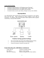
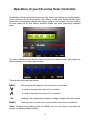
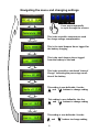
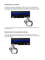
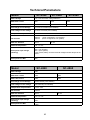
SC SERIES SOLAR CONTROLLER
USER MANUAL Ver 1.0
(for SC-2420, 2430, 2440, 2450, 2460,4840 and 4860)
1
2
Solar Controller
“SC” series solar controller USER MANUAL
Congratulations on choosing a ROC-SOLID “SC” series solar controller.
To ensure your safety and to get the most from your purchase, please read
these instructions carefully before use.
Safety First
Potenal safety concerns have been considered in the design of the ROC-SOLID
solar controller. Your ROC-SOLID solar controller is designed to convert power
from your PV cell/array and as such may produce significant potenal energy at
the output load terminals, even when a load is not connected. For this reason
the correct sequence of connecon and disconnecon of the solar controller
must always be followed. Below is a quick guide to help in the correct
installaon of your ROC-SOLID solar controller.
Installation considerations:
1)
2)
3)
4)
We recommend installation of this product be conducted by qualified
professionals.
Systems must be designed so that the nominal voltage of solar panel,
battery and loads are the same. (ie all 12V, 24V or 48V not a mixture)
Systems must be designed so that the rated current of solar panel and
the load(s) are smaller than the controller rating.
Choose an installation location for the controller which:
A)
Is out of reach of children
B)
Is out of direct sunlight and rain
C)
Is away from any volatile or explosive environment
D)
Is away from electrical heaters, or any other heat source
E)
Is away from wet areas or areas subject to rain ingress
F)
Minimizes the length of cables required for the Solar panel, battery
and load connections.
Installation check’s:
1)
Make sure the positive and negative terminals of the Solar panels, Battery
and Loads are all connected correctly, are clean and are tightened firmly.
3
2)
Check the diameter of the connecting cable is adequate for the requirements
of the current. Wire which is too small will result in voltage loss and poor
system performance. It may ultimately result in fire as the wire overheats
and breaks down. ROC-SOLID suggest the following minimum wires cross
sectional sizes:
Model Number
Wire size
Model Number
Wire size
SC-2420
3mm2
SC-4840
6mm2
SC-2440
4mm2
SC-4860
8mm2
sc-2460
6mm2
Controller connections should be made in the following order:
1)
2)
3)
Battery
Solar Cell
Load (ensure the load is “off” to minimize arcing on connection)
(Note: disconnection must be made in the reverse order)
Features
The ROC-SOLID SC series solar controllers use a microprocessor to provide
SOC (state of Charge) management functions, which in turn controls the charge
current using PWM technology and controls the supply of power to the load(s)
according to the voltage and capacity of battery. The controllers have the
following functions:
Standard Features:
∗ LCD display shows the battery volts, charging and load current alternately.
∗ Data logging of charge and discharge currents.
∗ Automatic system voltage sensing for 12/24V application
∗ 48V units are for 48v systems only.
∗ Default load off voltages are 12V system 10V off, 24V system 20V off, 48V
system 40V off.
∗ Controller can simultaneously charge battery and supply load
∗ Reverse Polarity Protection for Solar panels.
∗ Lightning surge protection
Battery control functions:
∗
∗
∗
∗
∗
On completion of charging, maintain the battery on “float” (user settable)
Prevent the battery from over-charging.
Prevent the battery from over-discharging.
Reverse Polarity Protection for Battery.
Automatic temperature compensation -3mV/degree C
4
Load control functions:
∗
∗
∗
∗
Load over current protection, LCD display shows “Overload”.
Load short circuit protection, LCD display shows “Short circuit”
Automatic load disconnect at low battery (user settable)
Automatic load reconnect upon battery voltage recovery (user settable)
Connection
Your ROC-SOLID solar controller has 6 terminals for connection to your battery,
solar cells and load. These terminals are clearly marked for your ease of
connection. Your battery, solar cells and loads all have separate earths (negative
connections), never join them together.
Caution during system testing!
◊
◊
◊
Do not illuminate solar panels with standard lights for testing.
Do not use a DC power supply in lieu of solar panels.
Ensure the battery is always connected first.
Understanding the LED Status indicators
Green LED on
Red LED on
Red LED is flickering
Loads are normally working
Battery is fast charging
Battery is charged and in float condition.
5
Operation of you CS series Solar Controller
Immediately following the initial power-up, the screen will display the model number
of the controller for a few seconds, then default to the main screen below. Upon
Initial start up the battery charge-off voltage, loads cut off voltage, Load-on Voltage
of loads reset will be the factory defaults unless you have previously changed
them.
The solar controller has 5 buttons used to select the display mode and modify the
default settings to the user requirements.
These buttons are used as follows:
MENU:
Will progress the display to the next item on the menu
Is used to increase the value (if it is variable)
Is used to decrease the value (if it is variable)
OK:
RESET:
Displays the instantaneous battery voltage, charge and load current
Recovers the unit from over current load or short circuit conditions
*Note: Pressing and holding down the MENU key for more than 5 seconds will
restore the factory default settings
6
Activating the circular display mode
No matter what is displayed on the screen you can press the “OK” button and the
unit will begin to display the instantaneous measured battery voltage, Charge
current and Load current in sequence. Each will be displayed for about 5 seconds.
7
Navigating the menu and changing settings
Press menu repeatedly
to cycle through the screens
This is the controller temperature used
for charge voltage compensaon
This is the total Ampere Hours logged for
the baery charging
This is the total Ampere Hours logged
from the baery to the load
This is the controllers calculated “state of
Charge” indicang the percentage condion of the baery
This se ng is user definable. Use the
and
buons to change se ng
This se ng is user definable. Use the
and
buons to change se ng
This se ng is user definable. Use the
and
8
buons to change se ng
Resetting the controller
If the controller display is showing either “Short circuit” or “Overload Reset” the
controller will require manual resetting once the problem has been fixed. To clear
these displays and reset the functionality of the controller, press the reset button.
The controller will restart and if the problem has been rectified the controller will
operate as normal.
Restoring the Factory default settings
To restore factory default settings press and hold the “MENU” button for 5 seconds. The display will show “Loading defaults” and the controller will restart using
the default settings.
9
Technical Parameters
Model
SC-2420
SC-2440
SC-2460
Rated Voltage
12V / 24V Automatic voltage detection
Max Solar current
20A
40A
60A
Max Load current
20A
40A
60A
Full charge cut out Voltage
13.7V/27.4V Default (user settable)
Low voltage cut out voltage
10.5V/21V Default (user settable)
Temperature compensation
-3mv/ /cell
No load loss
≤20mA
≤30mA
(when configured in 12V system)
(when configured in 24V system)
Max wire diameter
6 mm2
8 mm2
Ambient temperature
-25
Solar panel input voltage
(working)
20V (12V System)
40V (24V system)
*note: panel, battery and load nominal voltages should always be the
same
Solar panel Voc Max
50V
Model
to +55
SC-4840
SC-4860
Rated Voltage
48V
Max Solar current
40A
60A
Max Load current
40A
60A
Full charge cut out Voltage
54.8V Default (user settable)
Low voltage cut out voltage
42V Default (user settable)
Temperature compensation
-3mv/ /cell
No load loss
≤40mA
Max wire diameter
8 mm2
Ambient temperature
-25
Solar panel input voltage
(working)
60V
Solar panel Voc Max
100V
8 mm2
to +55
10
Trouble Shooting
Problem
Green light goes out, the loads stops working, and LCD shows
“Battery low”
Reason
Low battery voltage
Possible solutions:
1) Disconnect the loads and restart the controller by pressing
“RESET”. When the battery reaches the fully charged condition,
reconnect the loads.
2) Increase solar panel’s power and/or increase battery capacity.
Problem
Green light goes out, the loads stops working, and LCD shows
“Over load”
Reason
Solution
Problem
Overload
Reduce the quantity of loads and then press “RESET”
Green light goes out, the loads stops working, and LCD shows
“Short circuit”
Reason
Solution
The load has short circuited
Remove the short circuited load or rectify the problem, then press
“RESET”
Problem
Reason
Solution
Red LED goes out
Battery is completely flat
This condition is most often experience during the night when solar
energy is not available to charge the battery. Careful calculations
should be made to ensure the loads being operated have sufficient
battery capacity and charging capacity for continuous operation.
For any fault conditions not covered above, please contact your ROC-SOLID
dealer. There are no user serviceable parts inside the controller. Attempts to
repair a fault by untrained persons may result in undesirable and even potentially
dangerous outcomes. If after contacting your ROC-SOLID dealer the failure
mode is still persisting, the controller will need to be returned for repair/
replacement.
11
“ROC-SOLID” is a trademark of Ingenium Ruggedised Technologies, who is the
master distributor/Agent for ROC-SOLID solar and ROC computing products
www.roc-solid.com.au
12