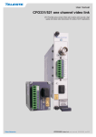
1
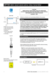
User manual
COR Optical repeater
for singlemode fibre
COR series optical repeaters are meant for systems requiring
extreme fibre transmission distances. ey provide an additional 20 dB link budget for any ITU-T compliant CWDM wavelength or standard 1310 nm used in a CFO system.
COR series optical repeater user manual, 59300297, rev002
Contents
COR - optical repeater .............................................................................................................................................. 2
General .............................................................................................................................................................. 2
Features ............................................................................................................................................................. 2
COR - optical repeater front panel .......................................................................................................................... 3
General .............................................................................................................................................................. 3
Frame installation ............................................................................................................................................... 3
Module indicator led ........................................................................................................................................... 3
Stand-alone installation ...................................................................................................................................... 4
Fibre connection................................................................................................................................................. 5
Optical signal levels............................................................................................................................................ 5
Function.............................................................................................................................................................. 6
Technical specifications........................................................................................................................................... 7
Application example ................................................................................................................................................. 7
COR series optical repeater user manual
1
COR - optical repeater
Configurable bi-directional optical repeater to cover extreme
transmission distances over singlemode optical fibre.
Welcome, and thank you for purchasing Teleste’s CFO Products.
General
COR repeaters are part of the extensive CFO OP-X platform that
complies to ITU G.694.2 CWDM grid. Also basic 1310 nm operation is
supported. These non-regenerative repeaters provide a cost effective
way to cover extreme transmission distances over optical fibre. Depending on system up to two or three repeater units can be connected in
series to make a line in which each leg have a maximum of 20 dB link
budget available for bi-directional operation.
The COR repeaters are configurable products meaning that the
operational wavelenght can be selected upon customer specification.
A typical repeater configuration supports fully bi-directional operation
but has also option to be defined for uni-directional operation as well.
The COR repeaters are optically compatible with all earlier generation
digital CFO video modems (SMF 1310 nm and CWDM models).
The COR series fits into all standard CFO installation systems allowing
both rack or standalone adaptor type operation. The COR series is
temperature hardened.
As with all CFO platform products these specific models do meet
all typical EMC as well as other environmental and manufacturing
related requirements.
Features
•
•
•
•
•
•
•
•
2
Bi-directional operation in same wavelength
Complies to ITU G.694.2 CWDM grid
High performance
Same units for rack mount or stand-alone
Mechanically compact and ruggedised
International EMC and environmental conformance
Compatible with all CFO installation systems
Optically compatible with older generation CFO video modems
(e.g. CFOx41 and CVM series)
COR series optical repeater user manual
COR - optical repeater front panel
CAUTION:
THESE OPTICAL UNITS USES CLASS 1M LASER DIODE.
DO NOT STARE INTO BEAM OR VIEW DIRECTLY WITH OPTICAL
INSTRUMENTS. APPLICABLE STANDARD IEC60825-1: 2001
1
General
OPTICAL REPEATER
Frame installation
PORT 1
2
The COR module is to be pushed along the guide rails into
the installation frame (e.g. CSR216 or 316 series) and secured with
the four locking screws. The unit can be freely positioned in any slot in
the frame. The empty positions in the frame should be blanked off with
cover plates. The supply voltage is to be provided by a CPS384 or
CPS390 power supply unit which are installed back of frame.
PORT 2
3
5
Module indicator led
SERVICE
4
The COR units are configurable bi-directional optical repeaters for CFO
OP-X platform that complies to ITU G.694.2 CWDM grid.
The COR contains a MODULE indicator which informs generic status
of the unit.
MODULE
6
1550nm
Ch15
COR Optical Repeater
Colour
Status
Green
Normal operation
Red
Supply voltage is not in the permitted range or
a hardware failure
MODULE indicator operation.
1) Locking screw (4 pcs)
2) Port 1, optical forward input / return
output (SC/APC 8°)
3) Port 2, optical return input / forward
output (SC/APC 8°)
4) Service connector (RJ-45 female)
5) Module indicator led
6) Handle (with wavelenght and
channel information)
See further information on
dedicated sections.
COR series optical repeater user manual
3
rear view
Stand-alone installation
CONTROL
BUS
The unit can be installed for stand-alone use by using a CMA021 module
adapter (installation for 10HP wide CFO series units).
The module should be mounted to a vertical surface. The +12 VDC supply
voltage is supplied by the means of a separate mains adapter with a
regulated output, (e.g. CPS231). Please refer to separate documention for
module adapters and mains adapters.
CONTROL/
ALARM
1
6
The permitted supply voltage range is 10.5...14 VDC. The current consumption is max. 100 mA (+12V DC). The permitted operational tempera-
11
1
POWER
2
+ 12 V
GND
CMA021 module adapter
1) Grounding connector
2) Supply voltage connector
Other interfaces are not in use.
CPS231 power supply with connector.
4
COR series optical repeater user manual
ITU Ch
Wavelength
11
1470 nm
12
1490 nm
13
1510 nm
14
1530 nm
15
1550 nm
16
1570 nm
17
1590 nm
18
1610 nm
Available ITU G.694.2 wavelength
channels for COR units.
Fibre connection
COR optical repeaters are designed to operate on ITU specified CWDM
optical channels. Configurable properties are that wavelenght for
forward direction and return direction can be choosen separately.
However, in a typical CFO OP-X system channel is the same to both
directions. The optical connector type is SC/APC 8°.
When installing the fibre optic cable, do not exceed the minimum
bending radius when connecting cable to the system.
For correct optical operation ensure that:
* Protect opened connectors always with dustcaps.
* Use only 8° angle polished SC/APC connectors, other connector
types will damage the interface.
* Clean all connectors before mating by using metyl or isopropyl
alcohol and dry connectors by compressed air.
Optical connection meets class 1M laser safety requirements of IEC
60825-1: 2001 and US department of health services 21 CFR 1040.10
and 1040.11 (1990) when operated within the specified temperature,
power supply and duty cycle ranges.
INVISIBLE LASER
RADIATION
CLASS 1M
front view
Optical signal levels
The optical output level is typically -1 dBm to both directions. However
the allowed optical input levels are different and are for forward input
direction -5...21 dBm and for return input direction 0 dBm...-21 dBm.
When testing the units it is advised in addition to a short fibre
patch cable to use always an optical attenuator to guarantee
system safe operation. In most cases a recommended attenuator
value is at least 5 dB. Please check also that a high quality doped-fibre
attenuators are used (air-gap attenuators may cause difficulties on link
association due to a poor reflection loss performance).
The optical connector type is SC/APC 8°.
COR series optical repeater user manual
5
Function
Optical signal routing inside the optical repeater module.
OPTICAL REPEATER
PORT 1
Forward input
Return output
Forward
622 Mbps...2.5 Gbps
PORT 2
Return input
Return
622 Mbps...1.25 Gbps
SERVICE
Forward output
MODULE
1550nm
Ch15
6
COR series optical repeater user manual
Technical specifications
Optical, forward path
General
Received wavelenght
1290...1330 and 1470...1610 nm
Supply voltage
12 V / 100 mA
Transmitted wavelenght
* configurable, CWDM ch or 1310 nm
Power consumption (max)
1200 mW
Input level range
-5 dBm...-21 dBm
Dimensions (H x W x D)
3U • 10HP • 190 mm
Output power
-1 dBm
Weight
0.5 kg
Forward path link speed
622 Mbps to 2.0 Gbps
Operating temperature
-34...+74 °C
Optical connector type
SC/APC 8°
Storage temperature
-40...+85 °C
Optical, return path
without CMA
Humidity
0...95 %
EMC compatibility
EN61000-6-3, EN50130-4, CE
non condensing
Received wavelenght
1290...1330 and 1470...1610 nm
Transmitted wavelenght
* configurable, CWDM ch or 1310 nm
Input level range
0 dBm...-21 dBm
Output power
-1 dBm
* Factory set upon customer configuration, CWDM channels 11...18 or basic 1310
nm
Return path link speed
622 Mbps to 1.25 Gbps
Class 1M Laser Product
Optical connector type
SC/APC 8°
Typical values unless otherwise stated
Notes
Application example
Multiwavelenght CWDM system
Wavelenght
specific
repeaters
CEV
TX
ch11
CEV
TX
ch12
max
20 dB link budget
COM
Mux/
Demux
COM
Mux/
Demux
COR
RPT
ch11
COR
RPT
ch12
CEV
RX
ch11
max
20 dB link budget
COM
Mux/
Demux
COM
Mux/
Demux
CEV
RX
ch12
COR
RPT
ch13
CEV
TX
ch13
COR
RPT
ch13
CEV
RX
ch13
max
20 dB link budget
Single wavelenght point-to-point system
20dB
20dB
TX
x61
1310 nm
1310 nm
COR
repeater
1310
COR series optical repeater user manual
20dB
COR
repeater
1310
1310 nm
RX
x61
1310 nm
7
Copyright acknowledgements
Information in this document is subject to change without notice and does not
represent a commitment on the part of Teleste Corporation.
Copyright © Teleste Corporation. All Rights Reserved.
No part of this document may be reproduced, transmitted, stored in a retrieval
system, or translated into any other language without the express permission
of Teleste Corporation.
Teleste Corporation
Video Networks
P.O. Box 323
FIN-20101 Turku
FINLAND
www.teleste.com
WEEE directive
Directive 2002/96/EC of the European Parliament and of the Council on waste
electrical and electronic equipment (WEEE) obliges that producers appropriately mark electrical and electronic equipment with the symbol indicating
separate collection. This obligation applies to the equipment put on the market
in EU after 13 August 2005.
Teleste devices which belong to the scope of the directive have been marked
with the separate collection symbol shown below. The marking is according to
the standard EN 50419. The symbol indicates that the device has to be
collected and treated separately from unsorted municipal waste.
User manual revision history note:
The latest version is always available in pdf-format on our web site:
www.teleste.com
8
COR series optical repeater user manual
Notes
COR series optical repeater user manual
9
10
COR series optical repeater user manual
www.teleste.com