1
Shoring Suite
Version 8
User’s Manual
CivilTech Software
CivilTech
Software
2015
.
.
.
All the information (including technical and engineering data, processes, and
.
results) presented in this program have been prepared according to recognized
.
contracting and/or engineering principles, and are for general information only.
If anyone uses .this program for any specific applications without an
.
independent competent
professional examination or verification of its accuracy,
suitability, and .applicability by a licensed professional engineer, he/she does so
. and assumes any and all liability resulting from such use. In
at his/her own risk
no event shall CivilTech Software be held liable for any damages including lost
profits, lost savings, or other incidental or consequential damages resulting
from the use of or inability to use the information contained within the
program.
Information in this document is subject to change without notice and does not
represent a commitment on the part of CivilTech Software. This program is
furnished under a license agreement, and the program may be used only in
accordance with the terms of agreement. The program may be copied for
backup purposes only.
The program or user’s manual shall not be reproduced, stored in a retrieval
system, or transmitted in any form by any means, electronic, mechanical,
photocopying, recording, or otherwise, without prior written consent from
CivilTech Software.
Thanks to John J. Peirce, P.E., D.GE of Peirce Engineering, Inc. for his
invaluable review and feedback of this manual
Copyright 2015 CivilTech Software. All rights reserved.
Simultaneously published in the U.S. and Canada.
Printed and bound in the United States of America.
Published by
CivilTech Software
Web Site: http://www.civiltech.com
Page 1
.
.
.
TABLE OF CONTENTS
.
.
CHAPTER 1: INTRODUCTION, INSTALLATION
AND ACTIVATION .......................................... 4
.
.
Modules ...................................................................................................................................................
4
.
Problem and Troubleshooting .................................................................................................................
4
.
<Preview and Print Screen> ..................................................................................................................
4
Installation and Activation ...................................................................................................................... 5
CHAPTER 2: GENERAL MODULE ........................................................................................................ 7
Introduction ............................................................................................................................................. 7
A. General Input Page ............................................................................................................................. 7
B. Run Modules in Steps .......................................................................................................................... 8
C. User and Firm Page ........................................................................................................................... 8
CHAPTER 3 SHORING MODULE........................................................................................................... 9
Introduction ............................................................................................................................................. 9
Shoring Menu .......................................................................................................................................... 9
Running the Program .............................................................................................................................. 9
Samples.................................................................................................................................................... 9
A. General Page ...................................................................................................................................... 9
B. Pressures Page.................................................................................................................................. 11
C. Braces and Force Page .................................................................................................................... 13
D. Option Page ...................................................................................................................................... 15
E. Two Walls Page ................................................................................................................................ 17
CHAPTER 4: EARTHPRES MODULE .................................................................................................. 18
Introduction ........................................................................................................................................... 18
Warning!................................................................................................................................................ 18
EarthPres Menu .................................................................................................................................... 18
Running the Program ............................................................................................................................ 18
Samples.................................................................................................................................................. 18
A. General Page .................................................................................................................................... 18
B. Soils and Water Parameter Page ...................................................................................................... 19
<Soil Parameter Screen> ..................................................................................................................... 20
C. Active Side Page ............................................................................................................................... 20
D. Passive Side Page ............................................................................................................................. 22
E. Options Page..................................................................................................................................... 22
CHAPTER 5: SURCHARGE MODULE .................................................................................................. 24
Introduction ........................................................................................................................................... 24
Surcharge menu..................................................................................................................................... 24
Running the Program ............................................................................................................................ 24
Samples.................................................................................................................................................. 24
A. General Page .................................................................................................................................... 24
B. Point Loads Page .............................................................................................................................. 25
C. Line Loads Page ............................................................................................................................... 26
D. Strip Loads Page .............................................................................................................................. 26
E. Area Loads Page ............................................................................................................................... 27
F. Infinite Loads ................................................................................................................................... 28
G. Railroad Load Page ......................................................................................................................... 28
CHAPTER 6: HEAVE MODULE ............................................................................................................ 29
Page 1
.
.
.
Introduction ........................................................................................................................................... 29
.
Heave MENU ........................................................................................................................................ 29
.
Running Program .................................................................................................................................. 29
.
Samples..................................................................................................................................................
29
.
A. General Page ....................................................................................................................................
30
.
B. Soils Page..........................................................................................................................................
30
.
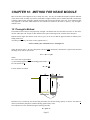
CHAPTER 7: METHOD FOR SHORING MODULE ........................................................................... 31
7.1 Terminology.................................................................................................................................... 31
7.2 Arching ........................................................................................................................................... 31
7.3 Vertical Bearing Capacity .............................................................................................................. 32
7.4 Embedment Calculation .................................................................................................................. 33
Users are responsible to have adequate Factor of Safety (F.S.) in embedment based on project
condition. There are two ways to apply F.S. in embedment. One is input F.S. in Option page D., Item
15. It will reduce passive pressure by dividing the pressure by F.S. Another way is increasing
embedment length or total pile length based on calculated embedment from program. ...................... 33
7.5 Limited Penetration in Rock ........................................................................................................... 34
7.6 Adding Ms for Embedment Calculation ......................................................................................... 34
7.7 Normal Brace Level and Low Brace Level. (This option is removed from program due to the risk
of instability) ......................................................................................................................................... 35
7.8 Deflection Calculation: .................................................................................................................. 35
7.9 Pile Strength and Size..................................................................................................................... 37
7.10 Single Span Beam and Continuous Beam .................................................................................... 38
7.11 Pile Bulking .................................................................................................................................. 38
7.12 Step Wall Calculation ................................................................................................................... 39
CHAPTER 8: METHOD FOR THE EARTHPRES MODULE ............................................................ 41
8.1
8.2
8.3
8.4
8.5
8.6
8.7
8.8
8.9
Flexible Wall and Rigid Wall ......................................................................................................... 41
Ko and Ka Conditions .................................................................................................................... 41
Apparent Pressure Envelopes......................................................................................................... 41
Method of Earthquake Analysis...................................................................................................... 43
Soil Parameter Screen and Relationship ........................................................................................ 44
Cohesion in Shoring Analysis......................................................................................................... 45
Earth Pressure Analysis ................................................................................................................. 45
Numerical Method vs. Equation Method: ...................................................................................... 48
Water Table and Seepage ............................................................................................................... 48
CHAPTER 9: METHOD FOR SURCHARGE MODULE .................................................................... 50
9.1
9.2
9.3
9.4
9.5
9.5
9.6
Strip Loads (Wayne C. Teng Equation).......................................................................................... 50
Area Loads ..................................................................................................................................... 50
Line Loads ...................................................................................................................................... 51
Point Loads..................................................................................................................................... 51
Infinite Loads.................................................................................................................................. 51
Railroad Loads ............................................................................................................................... 52
Flexible and Rigid Walls ................................................................................................................ 52
CHAPTER 10: METHOD FOR HEAVE MODULE ............................................................................. 53
10.1 Terzaghi’s Method ......................................................................................................................... 53
10.2 Hard Stratum ................................................................................................................................. 54
CHAPTER 11 QUESTIONS & ANSWERS …………………………………….……………………55
Page 2
.
.
.
Terminology:
. in the brackets corresponds to the item number in the program.
[ ] indicates a button or input item. The number
.
{} indicates a panel, a screen, or a module.
.
<> indicates a section in the Chapter 7-10 of the manual.
.
Z - depth starts from the wall top.
. bottom, or the dredge line.
Base -means the excavation base, excavation
. called penetration
Embedment – Pile length below the base, also
Page 3
.
.
.
.
.
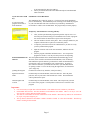
CHAPTER 1: INTRODUCTION,
INSTALLATION
.
AND ACTIVATION .
. two portions: Chapters 1-6 describe how to input data and run the
This manual of Shoring Suite version 8 has
program, and chapters 7-10 describe calculation
. methods and theories. The program may change frequently, and so
will the manual. Please check our web site for the new version (posted by date) of the manual and download it in PDF
format. To find the manual, go to the Download Page of our website: http://www.civiltech.com.
Modules
The program has 5 modules:
General: Used for software activation and modules arrangement. It is not necessary to input data in General module.
This module does not conduct any calculation.
EarthPres: Used for determining active, passive, and earthquake pressure from complicated soil, water, and ground
conditions.
Surcharge: Used for determining lateral pressure from the surcharge load on the ground surface, such as line, point,
strip, area, and railroad loading.
Shoring: Used for conducting analysis and design for shoring wall. Determining moment, shear, and deflection.
Finding pile length, pile size, brace force, and tieback length.
Heave: Used for checking if the shoring system is stable.
Each module has own files. The files should be saved within the own module. There is no way to save the
files from two or three different modules together.
The units for each module are shown in bottom bar of the module. Most time, kip and ksf are used instead
lb, or psf, except unit weight is pcf.
The top text menu is shared for all modules. When a module is clicked. It is the current module. Then the
top menu is only working for this manual
Problem and Troubleshooting
If you encounter any problems, please save your data file and send us an email with the input files for each module.
Most time, telephone call cannot solve the problem. Attached input files and email can solve the problem quickly.
Email: [email protected]. Please review Chapter 11, Questions & Answers before contact us.
If you need administrative assistance such as USB problem, please email your request to [email protected]
Notes
In the program, if input item is in black, that means the item is important. If input item is blue, that means
the item is optional.
If an option is marked with a *, the option is set as the default and is the recommended option.
Modules share the top pull-down menu. If one module is active, the main menu will be used for that module.
Each module except the General module has several samples that can be opened by pull-down a list on the
right side of the top menu bar. Click [Results] button to run the samples.
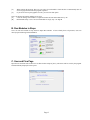
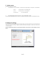
<Preview and Print Screen>
Most modules have the Preview and Print Screen when users press the [Results] button. There are buttons at the top of
the screen. The function of each button is described below:
Finger Right
Finger Left
View Page Height
View Page Width
Zoom In
Zoom Out
Printer
If there are more than one page, turn to next page
If there are more than one page, turn to previous page
Zoom to the page height
Zoom to the page width
Enlarge the image
Shrink the image
Send to printer
Page 4
.
.
.
Set up printer. For some Windows system, this button has no function or
.
removed.
. graphics to Windows Clipboard. Users can paste the graphics into
Copy the
. program, such as MS-Word, Power Point, and Excel.
any Windows
Saves .graphics to a Windows metafile, which can be opened or inserted by
other drawing
. programs for editing.
Close .Preview
Printer Setup
Clipboard
Save
Close Door
Installation and Activation
The program has two activation methods: USB key activation and code activation. Prior to activation, the
program is in demo mode. In demo mode, some functions of the program are disabled. Please follow the
installation and activation procedures below that correspond to your version of the software.
USB key:
Introduction of USB key
If you have CivilTech
USB key, the program is
inside the key. You can
run the program from the
key...
Civiltech USB key functions the same way as a USB flash drive, (also
called memory sticks or jump drive), but with a special chipset inside. It
has a memory of 128 MB, and USB 2.0 connectivity. The key is
compatible with Windows 2000, Xp, 7, 8 or higher, but may not work
with Windows 98 (You need to install USB driver for Win98).
Insert the key into any USB port in your computer. If you do not have an
extra USB port, you should buy a USB extension cord (about $10-$20)
Wait until the small light on the back of the USB key stops flashing and
stays red. This means that Windows has detected the USB key. A small
panel may pop up that says “USB mass storage device found”, you can
either close this panel or click “OK”.
Do not remove the key while the light is blinking, as that will damage the
key. You can remove the key only during the following situations:
1. Your computer is completely turned off, or
2. You have safely ejected the key from the system. You can do this by
going down to the Windows task bar, finding the icon that says
“Unplug or Eject Hardware” (usually located at the bottom right-hand
side of the screen) and clicking on that. It will then tell you when it is
safe to remove the hardware.
Running the Program within the Key.
No installation is required.
After you insert the key, use Windows Explorer (or click My Computer) to
check the USB drive (on most computers, it is either called D:, E:, or F:).
You will find some files inside. There is a folder called “/Keep” inside. Do
not change, remove, or delete this folder or the files inside, or else your key
will become void.
You will find a folder called “/Shoring8”. Open this folder and find
ShoringSuite.exe. Double click this program to run it from your key.
You can also create a new folder, save and open your project files directly
to and from your key. There should be enough room on the key for your
files.
Running the Program from your Hard Disk:
You can also run the program from your hard disk; the program may run a
little bit faster from your hard disk.
There is a file called sh_setup.exe in the root directory of the key. Doubleclick on the file to start installation.
The installation process will help you to install the program on your local
hard disk. Installation to network drive or disk is not recommended. The
program may not work properly.
The installation will create a shortcut on your desktop. Click the icon to
start the program.
You still need to plug the USB key into the USB port to run the program.
Page 5
If you do not have USB
key:
If you received the
program from email or
from download…
.
.
.
It will automatically detect the USB key.
. activation status can be checked from Help in General Module
The key
under.Activation.
.
.
Installation to Local Hard Disk:
.
. file is called sh_setup.exe. Click it will start up the installation
The installation
process automatically. The installation process will help you to install the program
on your local hard disk and create a shortcut on your desktop. Installation to
network drive or disk is not recommended. The program may not work properly.
Temporary Activation before receiving USB key.
After you have purchased the program and paid for express service we
will send you an email to help you to download a full version of program.
You need to follow the instruction to open an activation panel.
The CPU number is shown on the panel. This is a unique number for your
computer, which must be reported to CivilTech by email.
A temporary activation code will be emailed back to you after we verify
you have purchased the program.
Input the activation code in the Activation Pane, and then close the
program.
Start the program, which has full function now. You can open the
program for 20 times. You may run many times for each opening.
Download Manual from The most updated manual can be downloaded from Download page of our
Web site (www.civiltech.com/software/download.html). Click on Shoring
Internet
Suite Manual to open the manual, (you must have Adobe Acrobat Reader to
open the file). Then, save the PDF file onto your hard drive. If you have
slow internet connection, you should save the file to your hard disk instead
of opening it online. To save the file, using the right mouse, click and select
{Save Target As].
Quitting the Program
From the File menu of any modules, select [Exit Suite].
Input Firm and User
Name
From the Help of General Module, select Firm and User. Once the panel
pulls out, enter in your firm’s name and the user’s name. This information
will be printed in the report.
About Program and
Version
From the Help of General Module, select About. This will provide you with
the version of the program. Click anywhere on the screen to exit back to the
program.
Important:
It is not necessary to input data in General module. This module does not conduct any calculation.
Each module has own files. The files should be saved within the own module. There is no way to save the
files from two or three different modules together.
The units for each module are shown in bottom bar of the module. Most time, kip and ksf are used instead
lb, or psf, except unit weight is pcf.
The top menu is shared for all modules. When a module is clicked. It is the current module. Then the top
menu is working for this manual.
Page 6
.
.
.
.
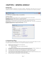
CHAPTER 2: GENERAL
MODULE
.
.
Introduction
.
This module manages the appearance of the
. other four modules. Inputted data in this module can be sent to four
modules to save time. It is not necessary to.input data in this module. This module does not conduct any calculation.
Pull Down Menus
File: General module cannot open and save files. You need to open and save files in each module.
Help/Help Read the help manual or press F1 to open the help manual.
Help/Troubleshooting: If you encounter any problems, please save your data file and send us an email with the
attached data file. We will respond to you as soon as possible. Email: [email protected]
Help/Activation: Use this to open {Activation Panel} and to input the activation code. If you have a CivilTech USB
key plugged in your computer, you do not need to activate your program.
Help/Users and Firm: Use this to input user and firm data.
A. General Input Page
This module does not do any calculation. The data in this module can be sent to all of the other modules to save time.
It is ok not to input data in General Module. You can input data individually in each module.
[1]
[2]
[3]
[4]
[5]
[6]
[7]
Height is from the wall top to the base line (dredge line).
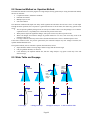
Select wall type in two groups:
Sheet pile group. In this group, [3] and [4] should equal 1.
Soldier pile group.
Pile Diameter: In the Soldier pile group, for diving piles, input the width of the pile flange or diameter, and
for drilled shaft, input the diameter of the shaft. For the Sheet pile group, input 1.
Pile Spacing: For the Soldier pile group, input lagging space. For the Sheet pile group, input 1.
After inputting and selecting data, press [5] to automatically send data to the other modules.
You can choose between either English or Metric units. The units chosen are shown on the bottom in each
module. Selecting a new unit will clear all the data in all modules.
This option keeps the {General Module} on top of all the other modules.
Page 7
.
.
.
[8]
When opening the program, there are cover pages for each module. Check this box to automatically turn off
. is opened.
all cover pages the next time the program
[9]
If you do not want to print graphics. in color, you can select this option.
.
Users can arrange and run the modules in two
. ways:
[A]
Users can arrange each module as .a separate window and run each module one by one.
[B]
Run Modules Steps - Users can run. each module in step by step. See Page B
B. Run Modules in Steps
Users can run each module in steps based on input data available. If users already have soil pressures, users can
directly input in Shoring without EarthPres.
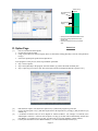
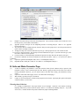
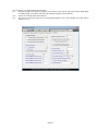
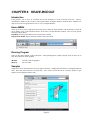
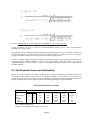
C. User and Firm Page
Input the user and firm name in the boxes as shown below and press [Save]. The names will be saved by the program
and automatically displayed on the reports.
Page 8
.
.
.
.
.
CHAPTER 3 SHORING
MODULE
.
.
Introduction
. Based on the pressures, it determines the moment, shear, deflection,
{Shoring} requires users to input soil pressures.
.
pile size, brace reaction and embedment of a shoring system based on DM-7 (U.S. Navy Design Manual), USS (Steel
Sheet Piling Design Manual), and FHWA-RD-75 (Federal Highway Design and Construction Summary).
program can be used to analyze and design sheet pile walls, soldier pile walls, and a variety of shoring walls.
There are a pull-down menu, menu bar, and total of 5 pages. A description of each item is listed below.
The
Shoring Menu
At the top of screen, there is pull-down menu. This
menu is shared by all the modules, and will change to
reflect the active module. Usage of this pull-down
menu is as the same as in most Windows software.
Here are some specific functions of Shoring menu:
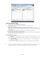
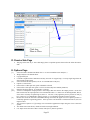
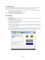
File/Open: V8 can open V6 and 7 files from [Files
of Type] list as shown in right Figure. Because V8
adds many new fields, Users need to modify the V6
and V7 before run the program.
Edit: enabled when users clicks one of the tables on
Pages B, C, and D. Users can insert, delete, copy,
and paste a row of data in the table.
Help/Help: Provides general help on how to use the
Shoring module.
Help/General Module: Opens {General} module if it has been closed.
Running the Program
There are three major buttons on the top menu bar. After inputting data or opening a sample, users can press one of
these three buttons to run the program:
[Results]
[Report]
[Diagram]
View the graphics and results
See text results
View and print shear, moment, and deflection diagrams.
Samples
Sample files can be opened from the list on top right of menu bar. Samples that start with E are in English (Imperial)
units. Those that start with M are in metric units. Users need to switch units in the {General} module to open
samples of either English or Metric units.
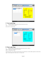
A. General Page
This page is for general information. Title 1 is the project title (text only). The {General} module can overwrite this
text if the user presses [5. Send data to all modules]. {EarthPres} also will overwrite it when the [Send to Shoring]
button is pressed. Title 2 is the subtitle (text only).
Page 9
[1]
[2]
.
.
.
Height is from the wall top to the base line (dredge line). The {General} module can overwrite the text if the
.
user presses [5. Send data to all modules]
. right side of the screen indicate the wall types.
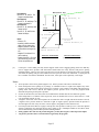
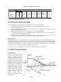
Select a wall type. Drawings on the
For a Sheet piles, [3. Pile diameter]. and [4. Pile spacing] should be equal to 1.
For Soldier piles, users can choose.between drilled shaft and driving pile. For details, refer to <7.2 Arching>.
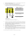
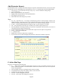
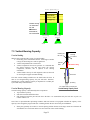
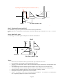
A sample is shown in the figure. Pile
. #1 in the figure has two active spacing and two passive spacing.
.
Pile Spacing S
Example: For Pile #1
Assume Arching=2
Lagging
Active Spacing=S
Active Spacing=0.5S
Pile #1
Active Width=D1
Passive Width=2D1
Pile #2
D1
Active Width=D2
Passive Width=2D2
D2
General Rule:
Active Spacing=S (above base called spacing)
Active Width=D (below base called width)
Passive Width=2~3D (below base, including arching)
.
[3]
[4]
[5]
[6]
[7]
Pile diameter. For a driven soldier pile, enter flange width. For a drilled-in soldier pile or drilled shaft, enter
the diameter of the drill hole. The hole should be back filled with concrete or lean concrete. Some people
advocate filling the drilled hole with stone or soil. If so, use the pile flange width. For sheet pile, concrete,
slurry wall, and trench box enter 1. English unit: 1 foot; Metric unit: 1 meter.
Pile spacing. For a soldier pile, enter lagging spacing. For sheet pile, concrete, slurry wall, and trench box
enter 1. English unit: 1 foot; Metric unit: 1 meter.
After inputting data from [1] to [4], press [5] to automatically write data to [6] and [7].
Depth and spacing for active pressures. Above the base, enter lagging spacing. Below the base, enter pile
diameter. No arching should be applied to active spacing. For sheet pile, concrete, slurry wall, and trench
box, spacing = 1. English unit: 1 foot; Metric unit: 1 meter.
Depth and spacing for passive pressures. The depth should start from where the passive pressure starts, most
of time it is at the base. The spacing is including passive arching. Enter pile diameter and multiply the
passive arching. For details, refer to <7.2 Arching>. For sheet pile, concrete, slurry wall, and trench box,
spacing = 1. English unit: 1 foot; Metric unit: 1 meter.
Users can directly input [6] and [7] without press [5] or modify [6],and [7] after pressing [5].
Page 10
.
.
.
.
.
.
.
.
.
B. Pressures Page
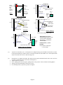
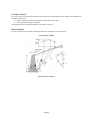
[1][2]
Input active and passive pressures in tables: A pressure is a trapezoid polygon that is defined by 2 depths
and 2 pressures called Z1, Z2, P1, and P2. A slope is defined as:
Slope = (P2-P1) / (Z2-Z1)
One trapezoid polygon occupies one row of data in the table. Users have 3 options in [3] to input data.
[3]
Select one of the three options in the Input Options box. Users only need to input four values for each
pressure. The program can remember the option as default option when the program is closed. When users
open the program next time, the option is automatically selected.
[Input P2 => Slope]: input Z1, P1, Z2, and P2, the program will calculate Slope.
[Input Slope => P2]: input Z1, P1, Z2, and Slope, the program will calculate P2.
[Double click on –>]: If users input Z1, P1, Z2, and P2, double-clicking on Slope will get the Slope data. If
users input Z1, P1, Z2, and Slope, double-clicking on P2 will get the P2 data.
Users can input comments in a row by typing a * in the 1st column. The rest of the columns are then ignored
and can be used for comments or remarks. Each input cell can only hold 5 characters.
Page 11
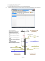
Notes:
• Z2 must > Z1
• Input 800 or 999 for unknown
depth of Z2 (by double click)
• Negative pressure is allowed,
represented in the diagram by
red.
• Negative Z1 is allowed if it is
above a wall top.
• Double-clicking Z1 or P1 of the
next row will copy the Z2 and
P2 from the previous row.
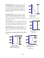
[4]
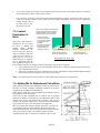
Wall/Pile Top
Z
Z1 top
Top Pressure, P1
Wall Height
Input Option 1:
Input Z1, P1, Z2, and P2. The
program calculates Slope.
Input Option 2:
Input Z1, P1, Z2, and Slope. The
program calculates P2.
Input Option 3:
Input Z1, P1, Z2, and Slope, then
double click P2.
Input Z1, P1, Z2, and P2, then
double click Slope.
.
.
.
.
.
.
.
.
.
Slope
Base
Z1 top
Top Pressure, P1
Slope
Z2 bot.
Bottom Pressure, P2
Pile Tip
Z2 bot.
Bottom Pressure, P2
Passive Pressures
(below Base)
Active Pressures
(above or below Base)
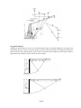
Corner pile: Corner soldier piles only need to support a half of active lagging spacing above base. But they
need to support active pressure with full width of shaft below base. They also have full passive spacing
including arching. However, the passive spacing can’t be more than active spacing above base. The program
will check the spacing and give 50% reduction of active pressure above base. Sometime, a corner pile can
have a smaller size and less embedment. In some cases, corner pile can be replaced by a steel angle.
Notes:
Active pressure can be above ground (negative Z1). Passive pressure can be above the base line.
Check the depth of active spacing in [6] of Page A. It should be above or equal to the depth of any active
pressures. It is the same for the passive spacing in [7] of Page A. For example, if the depth of the first passive
spacing starts with 10 feet, and the user inputs a passive pressure of Z1=-9 feet, the program cannot
determine the spacing for the passive pressure.
If users do not know Z2, enter 800 or 999 for an unknown Z2. Double click the Z2 column can get 800.
If the 2nd pressure is a continuo of the 1st pressure, users can double-click Z1 or P1 on the 2nd row. It will
copy Z2 and P2 from the 1st row.
A negative value of P1 or P2 can be inputted. If we assume the wall is on right side and excavation is on left,
a negative active pressure means it is from left to right. A negative passive pressure means the pressure is
from the right to the left. If any one of P1 or P2 is negative, the graphics will be shown in red.
For water pressure and if there is seepage at wall tip, the water pressure at wall tip is zero. Since the depth of
wall tip is unknown, users can input Z2=Tip, P2=0, Slope=to tip. If Earthpres module is used, these values
will be automatically generated and exported to Shoring module.
If the graphics show red color in pressure diagram, you may have negative value in pressure input.
Any passive pressures above excavation base is ignored by the program.
Page 12
.
.
.
.
.
.
.
.
.
C. Braces and Force Page
[1]
Select the type of braces and input data in the table below.
Depth is measure from top of wall. Negative values represent a brace above the wall.
Angle: clockwise is positive.
Spacing is the distance between two braces. It may or may not equal to pile spacing.
In sheet pile case, for wale and continuous brace, input spacing=1. In soldier pile case, input spacing = Pile
spacing. But you can have different spacing other than pile spacing. For example, pile spacing=6’ but
tieback spacing = 12’.
Input1 and Input2 are for different brace types. Refer to the instructions of [Help] on the screen.
For a mixed type, enter the brace type in the last column.
In the same column, if the data of the next row is the same as previous row, users can leave the data in blank,
which assume the data is the same. See Example E10.
Recommended Data for Input 2:
For tieback, Input 2 is allowable bond strength, which is the friction between tieback and soils. It is from
field tests.
For Plate Anchor, Input 2 is allowable pressure, which is from field tests. It can be estimated as Kp * Soil
unit weight * Depth.
For Deadman Anchor, Input 2 is allowable pressure, which is from field tests. It can be estimated as Kp *
Soil unit weight * Depth.
For Sheet Pile as Anchor, Input 2 is allowable pressure slope. It can be estimated as Kp * Soil unit weight.
[2]
No-load zone calculation: the tieback, deadman, and plate anchor should be located outside of the no-load
zone. Press [Auto] to get the recommended value. Press [Help] for a definition of the no-load zone.
Page 13
.
.
.
.
.
.
.
.
.
Wale or
Continue
Brace
Using
Spacing=1
Angle1=0
90-Angle2=(30 )
from H-Line
Strut
Angle1=(0)
Angle1 must =0
Input2=Passive Pressure=(1ksf)
(Depth*Passive Slope)
V-Line
Raker
Angle1= ( - 45)
Angle2=(60 )
from H-Line
There is no
Input1, Input2,
and Angle2
Wale
Program
will find
Height
Deadman
Strut and Raker
Input 1=
Width
Program find bond length
Angle1=(30 )
V-Line
Input2=(1ksf)
Bond strength
Angle2=(60)
from H-Line
H-Line
Input H/V Ratio=(0.25)
Angle1=(30 )
V-Line
Input1=(0.5’)
Anchor diameter
Angle2=(60)
from H-Line
H-Line
Input H/V Ratio=(0.5)
Tieback
Input2=Allowable
Pressure=(1ksf)
Plate Anchor
Chance anchor, Screwed, Plate or Helix.
90-Angle2=(30 )
from H-Line
Angle1 must =0
Input 1= Width
V-Line
Program
find pile
length
Angle2=(60 )
from H-Line
Input2=Passive Slope = (0.3kcf)
Sheet Pile as Anchor
[3]
Input1=Plate Diameter =(2’)
Program finds
number of plates
Brace Spacing: the horizontal
distance between two braces. It may
or may not equal to pile spacing.
Brace Spacing = 1 for Wale and
Continuous Brace
Numbers show in (...) are for
Examples
Passive Slope=Eqv. Density=Kp*G
G = Soil unit weight
Top brace is increased by 15%. The top brace in a multiple bracing system should be increased by 15% due
to unexpected surcharge at surface and over excavation for 2nd brace. (Ref. DM7.2-103). This option should
only be used in the case of two or more bracing levels.
.
[4]
External force: see [Help] for details. This table lets users input concentrated loads on the wall. Users also
can input vertical loads on top of the wall (see Sample E11).
Angle: clockwise is positive.
Force: Pushing on the wall is negative; pulling on the wall is positive. This is colored red in the graphics.
Spacing is the horizontal distance between two forces.
For external pressures, input active pressure on Page B.
Page 14
.
.
.
.
.
.
.
.
.
Force against wall [-]
Angle [+]
Force pulling wall [+]
Angle [-]
•
•
•
1.
2.
3.
Spacing is the horizontal distance between forces.
If the force is pushing against the wall, input a
negative value.
If the force is pulling on the wall, input a positive
value.
External Force
D. Option Page
[1]
Vertical Force [-]
Angle=90
Pile size selection has three options.
No selection of pile in results.
Group of piles that meet moment capacity (these are listed after clicking [Results] as well as in the pull-down
list [2]).
Select user inputted pile specified in an adjacent box
To let program to select pile size, these steps should be performed:
Step 1. Select option 2.
Step 2. Press [Results] to the program. After this finishes, [2] will be filled with available piles.
Step 3. Open step [2] to select a pile. The selected pile will also be displayed adjacent to option 3 of [1]
[2]
[3]
[4]
[5]
Pull-down list of piles: users must select option 2 in [1] and run the program to get the list.
If users selected option 3 of [1] and entered pile name in the adjacent box, pressing [3] fills pile data in I [4]
and Ms [12].
I is Moment of Inertia: Units are in4 in English or 100cm4 in Metric. For example, if I=500cm4, users
should input 5 in the box. If the user selects options 3 in step [1], the data will be automatically entered from
pile database. For soldier pile, it is per pile. For sheet pile, it is per foot (English) or meter (Metric).
Use the pull-down menu to select Elastic Module, E. E will be automatically entered to [6].
Page 15
[6]
[7]
[8]
[9]
.
.
.
Users can modify E after selecting [5].
Select yield strength, Fy, for steel.pile. If the last line “ User Input in Item 8” is selected, then input Fb in
. you can select "User Input in Item 8", then directly input Fb in [8].
Item 7. If you use aluminum or wood,
. bending strength. Ratio=Fb/Fy. Therefore, Fb can be calculated by
Input ratio of Fb/Fy: Fb is the allowable
Fb=Ratio*Fy. Please refer to <7.9.Pile Size and Strength>. If you "User Input in Item 8", then directly input
Fb in [8].
.
Embedment Options:
.
Choose ‘Yes’ for regular shoring. The program will determine embedment to meet equilibrium requirements.
Choose ‘No’ for a no-embedment system such as a trench box or internal braces. The system must have at
least two or more braces.
If the user has an existing wall or fixed pile length, choose ‘Fixed’. The user needs to input the fixed
embedment in [10]. Please note, it is not total pile length. It is pile embedment. <7.4 Fixed Embedment>.
[10]
Enter fixed embedment. Please note, this is not total pile length; it is the pile embedment.
[11]
Friction at pile tip: If bedrock is encountered and pile embedment is limited, there may be friction between
pile and rock. Adequate penetration in rock is required to develop friction. Refer to <7.5 Limited Penetration
in Rock>.
Driving steel pile requirement: At least 2-3” penetration in rock
Drilled shaft requirement: At least 1’ penetration in rock
Based on the penetration in to the bedrock, following options should be selected.
If it does not meet the requirements, select [No]
If it is strong rock and meets the requirements, select [Unlimited]
If it is weak rock and meets the requirements, select [Limited] and input rock strength in the input box. The
rock strength is in ksf or kPa.
[12]
During embedment calculation, Ms can be considered as resistance to reduce the embedment. Ms is the
allowable capacity for movement in the pile. At least a 5' (1.5m) embedment is needed to develop Ms. (Ref.
DM7.2-103). Refer to <7.6 Ms>. Ms will automatically be entered if the user selects option 1 or 2 in step [1].
For soldier pile, it is per pile. For sheet pile, it is per foot (English) or meter (Metric).
[13][14] Check [13] then input vertical friction and Tip bearing capacity. Refer to <7.3 Vertical bearing> for details.
[15]
Input F.S for passive pressures. If the input pressures are allowable, use F.S > or =1. If the pressures are
imported from EarthPres and the soil parameters (friction and cohesion) in EarthPres are allowable, the
pressures are allowable. If the soil parameters or input pressure are ultimate, F.S .> or = 1.5 is recommended.
The inputted passive pressures are divided by F.S. during calculation. It is moved to Page B, Item 2.
[16]
Marking [16] can reduce the Maximum moment in the pile. Refer to <7.10. Beam Span>.
[17]
The graphics scale in [Results] and [Diagram]. After opening any sample, users can try it out by changing it
and pressing [Results]. Turn on or off the Deflection diagram in [Diagram]
[18]
Turn on and off the top deflection in [Results]. The top deflection is shown in ( ) followed pile each name,
when option 2 of [1] is selected.
[19]
Turn on or off the input data in [Report].
[20]
Turn on or off the Shear, Moment, and Deflection vs. Depth in [Report], which is a long list.
[21]
For cantilever wall only, the calculated embedment is increased by 20% to reach the design depth in the
program. Advanced user may modify this data. It does not affect braced wall.
[22]
[Diagram] button can show two options: 1. Pressure on the wall (ksf or kPa) or 2. Pressure x Spacing on wall
(kip/ft or kN/m). Check [22] to get 2nd option, which gives real loading for soldier piles. For sheet pile,
these two options are the same.
[23]
Negative depth (Z<0) of a pressure means the pressure is above wall top (Z=0). Check [23] will ignore any
pressures above wall top. Uncheck [23] will include the pressures above wall top, which usually present
lateral loading on railing, fence or pile head above ground.
[24][25] Users can open MS-Excel to edit the pile list data. The instructions are shown on top of the Excel file. If you
do not have Excel installed in your computer, this function cannot be activated.
Notes:
Users can directly find two database files. One is for Sheet pile and is named: SheetPile8.txt. The other is for
soldier pile and is: SoldierPile8.TXT. The two files are in the Shoring8 folder.
Page 16
.
.
.
.
.
E. Two Walls Page
. For three or more walls, users can analyze the top two walls first, and
This page is for calculating two stepped walls.
.
then continue in this manner for the rest of the walls. Refer to <7.12 Step Wall>.
.
The instructions are shown on the top of the page in red.
.
The data for Wall 1 and Wall 2 is automatically saved as files F1 and F2. Clicking [F1] or [F2] can retrieve
the file and rerun the analysis.
To see an example, please open example E19 and click on Step 1 and open the example file E20 and click on
Step 2.
Page 17
.
.
.
CHAPTER 4:. EARTHPRES MODULE
.
.
Introduction
.
{EarthPres} determines the lateral earth pressures
and hydrostatic water pressure on retaining structures. The program
. pressure,
can calculate active, passive, hydrostatic water
and earthquake pressures from a set of complicated surface
.
conditions. The results can be integrated into the {Shoring} module for shoring wall designs.
Warning!
It is strongly recommended that the user only use the friction angle to calculate soil pressures. Cohesion is not reliable
in shoring design. Using clay materials with zero friction and large cohesion in the program will lead to incorrect
results. Refer to <8.6 Cohesion in Shoring Analysis>.
EarthPres Menu
At the top of screen, there is pull-down menu. This menu is shared by all the modules, and will change to reflect the
active module. Usage of this pull-down menu is as the same as in most Windows software. Here are some specific
functions of EarthPres menu:
Edit: enabled when users click one of the tables on Pages B, C, and D. Users can insert, delete, copy, and paste a row
of data in table.
Help/Help: Provides general help on how to use the EarthPres module.
Help/General Module: Opens {General} module if it has been closed.
Running the Program
There are three major buttons on the top menu bar. After inputting data or opening a sample, users can press one of
these three buttons to run the program:
[View]
View the graphics but cannot print.
[Results]
View and print the results and graphics.
[Report]
See text results.
[Shoring]
Export results to the {Shoring} module.
Samples
Sample files can be opened from the list on top right of menu bar. Samples that start with E are in English (Imperial)
units. Those that start with M are in metric units. Users need to switch units in the {General} module to open
samples of either English or Metric units.
A. General Page
This page is for general information. General Title is the project title (text only). The {General} module can
overwrite this text if the user presses [5. Send data to all modules]. EarthPres Title is the subtitle (text only).
Page 18
.
.
.
.
.
.
.
.
.
[1]
Height is from the wall top to the base line (dredge line). The {General} module will overwrite the text if
the user presses [5. Send data to all modules]
[2]
Apparent pressure envelopes are the simplified pressures for shoring analysis. Refer to <8.3 Apparent
Pressure Envelopes >
1. The pressures that are calculated directly from the analysis. Some people like to use this option instead of
option 2 below (Triangle envelope ).
2. Triangle envelope: For no-braced wall with any soil type. Some people also use it for one-braced wall.
3-5. For one or more braced wall. The envelope is based on different soil types. If you know the soil type, select
this choice. Otherwise select option 5.
6. For braced walls, it will automatically determine the pressure envelope based on the majority soil types.
[3]
Ka and Ko conditions are based on whether the wall has movement. Refer to <8.1 and 8.2 Ko and Ka
Conditions >.
[4]
Options for generation Earthquake loads; refer to <8.4 Earthquake Analysis >.
[5,6]
Input Kh and Kv; usually Kv=0.5Kh, or zero. Refer to <8.4 Earthquake Analysis >.
B. Soils and Water Parameter Page
[1]
[2]
[3]
[4]
A table for inputting soil parameters. Users must click the button [Click to Define Soil] to open the {Soil
Parameter Screen} screen, and then input the data. Directly typing the data into the table will result in
missing information. However, you can edit the data in the table after closing {Soil Parameter Screen}
screen.
Options for water table and seepage; refer to <8.9 Water Table and Seepage >.
Water density, typically 62.4 pcf or 9.8 kN/m3
Usually, if users click File/New, all data in the program will be cleared. Specifying this option will keep the
soil data in table [1] for new files.
Warning about Cohesion:
It is strongly recommended to only input friction for soil strength. Cohesion is not reliable in shoring.
Inputting cohesion may lead to incorrect results! Refer to <8.6 Cohesion in Shoring Analysis>. If you still
want to use C, manual calculate the pressures and directly input in Shoring Module.
Page 19
.
.
.
<Soil Parameter Screen> .
Click the buttons in the 1 column of Soil Table
Page B to open the {Soil Parameter Screen} screen. Then, follow
. theinparameters,
the steps below. For the relationships between
refer to <8.5 Soil Parameter Screen and Relationship>
.
1. Select soil type. For clay and silt,.select type of Eqv. Clay. It is more suitable for shoring design.
2. Type soil description.
.
3. Move N1 (spt) to obtain the other parameters.
4. Slightly modify other parameter by. moving individual bars.
st
5.
6.
Press [Apply] to close the screen.
Edit the data on the table in Page B as you wish.
Notes:
Eqv. Clay - Equivalent Clay. It is strongly recommend using friction for shoring design; Cohesion is not
reliable in shoring. If the soils are clay or silt, select Equivalent Clay as soil type. This type soil converts
cohesion to equivalent friction based on N1(spt). Refer to <8.6 Cohesion in Shoring Analysis>.
N 1(spt) – Corrected standard penetration test (SPT) in field. If you do not have N1, use SPT.
CPT – Cone penetration test in field. If qc is available, users can move N(spt) until CPT=qc.
The other parameters will change with N (spt). If you know one parameter, such as friction, you can move N
(spt) until the friction reaches the desired value.
G is the total moist unit weight. Gs is the saturated unit weight. Gs will be equal to or larger than G.
Friction – internal friction angle (phi)
C – Cohesion of soil
English unit is on left side. Metric unit is on right side.
If you want to move N1 without changing other parameters, uncheck the Link Box on right side.
C. Active Side Page
This page is for inputting soil and water lines.
[1]
Input a series of ground lines on the table. Users have to select a soil number for this line. The soil
number is defined on Page B. It is assumed that the defined soil is under this line. Users need to input one
row per each ground line.
Select soil number and type by clicking the button in the first column.
Z is depth from the top of the wall. Negative means it is above the wall.
Xa starts from wall to the right - Active Side.
Xa, must = 0 at the starting point of the line.
Xa, must = 800 or larger at the ending point of the line.
Page 20
[2]
.
.
.
At end point, double click Xa to get 800
.
Two ground lines cannot intersect.
. view of your inputted ground lines.
The [View] button provides an instant
. The water line can be above the ground surface or above the wall top
Input one water line for the active side.
.
.
.
• One row per ground line.
• Select one Soil Type under each line.
• Z is depth from the top of the wall.
Negative means it is above the wall.
• Xa starts from wall to the right - Active
Side.
• Xp starts from wall to the left - Passive
Side.
• Xa, Xp must = 0 at the starting point of
the line.
• Xa, Xp must = 800 at the ending point of
the line.
(Double click to get 800)
• Water line can be above ground surface
or above the wall top.
Z=25
Xp=800
Line 1
Soil 4
+ Xp
Xa +
Z= - 6 Z= - 6 Z= - 4
Xa=15 Xa=25 Xa=28
ZZ=0
Xa=0
H
Z=0
Xa=10
Z+
Line 2
Soil 5
Line 1
Soil 5
Water Line
Line 2
Soil 1
Z=20
Xp=0
Z=25
Xp=30
Ref. Example: E06
(EXP06.EP8)
Line 3
Soil 5
Water Line
Passive Side
Active Side
Page 21
Z= - 4
Xa=800
.
.
.
.
.
.
.
.
.
Click to View
Click Any
Place to Close
D. Passive Side Page
This page is the same as [C. Active Side Page] above except that Xp starts from wall to the left at the Passive
Side.
E. Options Page
[1]
[2]
[3]
[4-7]
[8]
[9]
Select from three calculation methods refer to <8.7 and 8.8 Earth Pressure Analysis>)
Wedge analysis is the default choice
Log spiral analysis
Coulomb’s Equations have limitations and may not work for stepped slop, or a slope angle larger than the
friction angle of the topsoil.
Select from wall friction options (refer to <8.7 Earth Pressure Analysis>)
Option 1 is conservative.
If the wall is a soldier pile wall, option 2 should be selected.
If the wall is a sheet pile wall, option 3 can be selected (Only for Formulary Solution).
Input the friction in degrees. It is limited to 15 degree.
A factor is multiplied to output pressures. Factor larger than one increase the output pressure. Factor less
than one decrease the output pressure. The recommended value is 1. Please note: In Shoring module, there is
also a Factor of Safety in Option Page D, Item 15. The F.S. is only applied to passive pressure as item [5]
here. However, [5] is multiplied to passive pressure. F.S. in Shoring is divided to passive pressure.
Because the soil at the base line is distributed during excavation, the upper two feet of passive pressure is
commonly ignored in engineering practice. If the top of the excavation base is filled with concrete, users can
input zero here.
The pressures of option 1 of [2] on Page A are converted to apparent envelopes using one of two conversion
options:
The default conversion factors, which are based on Terzaghi and Peck.
Use- input conversion ratio. If this is chosen, items [10-12] must be specified.
Page 22
.
.
.
[10-12] Refer to <8.3 Apparent Pressure Envelopes>
[13]
Maximum height of wall shown in.graphics (not for analysis): the software will always output enough depth
. affects the schematics displayed in the [Results]
for shoring design. This option only
[14]
Turn on or off the input data in the.[Report]
[15]
This option can show the failure lines
. on the graphical diagrams. This is only available for wedge analysis
(Option 1 of [1]).
.
.
Page 23
.
.
.
CHAPTER 5:. SURCHARGE MODULE
.
.
Introduction
.
{Surcharge} calculates the lateral pressures
structures due to surcharge loads. The results can be
. on retaining
integrated into the {Shoring} module for shoring
wall
designs.
This program is based on Boussingesq’s equation
.
modified by Teng (USS Design Manual and NAVY DM7).
Surcharge menu
At the top of screen, there is pull-down menu. This menu is shared by all the modules, and will change to reflect the
active module. Usage of this pull-down menu is as the same as in most Windows software. Here are some specific
functions of Surcharge menu:
Help/Help: Provides general help on how to use the Surcharge module.
Help/General Module: Opens {General} module if it has been closed.
Running the Program
There are three major buttons on the top menu bar. After inputting data or opening a sample, users can press one of
these three buttons to run the program:
[Results]
[Report]
[Shoring]
View the results and graphics.
See text results.
Export results to the {Shoring} module.
Users have two options for sending the data to {Shoring}:
Combine all loads together and send the data to {Shoring} at one time. Only one surcharge pressure is sent to
{Shoring}.
Input each load individually and click [Send to Shoring] several times. Shoring will receive several surcharge
pressures and show several surcharge pressures on the diagrams.
Samples
Sample files can be opened from the list on top right of menu bar. Samples that start with E are in English (Imperial)
units. Those that start with M are in metric units. Users need to switch units in the {General} module to open
samples of either English or Metric units.
A. General Page
This page is for general information. General Title is the project title (text only). The {General} module can
overwrite this text if the user presses [5. Send data to all modules]. Surcharge Title is the subtitle (text only).
[1]
[2]
Height is from the wall top to the base line (dredge line). The {General} module will overwrite the text if
the user presses [5. Send data to all modules]
Depth of surcharge: input a positive number if the surcharge load is below the wall top, negative if it is above
the wall top
Page 24
.
.
.
.
.
.
.
.
.
[3]
[4]
Wall Condition; refer to <8.1 Flexible Wall and Rigid Wall> and <9.6 Flexible Wall and Rigid Wall>.
A flexible wall experiences less pressure because the pressure is released after the walls movement. The
calculated surcharge pressure of flexible wall is about 0.5 of the rigid wall.
A semi-flexible wall is between flexible and rigid, a small amount movement is allowed. The calculated
surcharge pressure of flexible wall is about 0.75 of the rigid wall.
A rigid wall experiences more pressure. If the movement is restricted by utilities and sensitive structures
behind the wall, this option is recommended.
Load factor for surcharge: Output pressure will be multiplied by this factor
If the surcharge is footing, input the load factor for a dead load
If the surcharge is traffic, storage or construction loading, input the load factor for a live load
If there are two loads, one is considered as a dead load and another is a live load, then the program needs to
be run twice and [Send to Shoring] needs to be pressed twice to use the different load factors.
B. Point Loads Page
X
Horizontal distance (perpendicular to wall) from the wall to the point load (feet or meters)
Y
Horizontal distance from the point load to the section of wall, where the pressure is calculated (feet or
meters). It is parallel to wall.
Qpoint Point load in kip/ft or kN/m
Please refer to <9.1 Point Load>
Page 25
.
.
.
.
.
.
.
.
.
C. Line Loads Page
X
Qline
Horizontal distance from the line load to the wall (feet or meters).
Line load in kip/ft or kN/m
Please refer to <9.2 Line Load>
D. Strip Loads Page
X
Width
Qstrip
Horizontal distance from the edge of strip load to the wall (feet or meters).
Width of the load applied (feet or meters).
Strip load in ksf or kPa
If the strip pressure is not uniform, then the pressure can be bricked in to several uniform pressures as shown in the
figure as well as sample E03. Please refer to <9.3 Strip Load>
Page 26
.
.
.
.
.
.
.
.
.
E. Area Loads Page
X
Width
Length
Qarea
Horizontal distance from edge of the area load to the wall (feet or meters.)
Width of the area load (feet or meters.)
Length of the area load (feet or meters.)
Area load in ksf or kPa
Please refer to <9.4 Area Load>
Page 27
.
.
.
.
F. Infinite Loads
.
The infinite loading has two options:
. It is based on active failure analysis. This option 1 is recommended.
1.
Conversional active or at-rest method.
.
. as active pressure. It is for flexible wall
p= Ka q
.
p= Ko q
p= (Ka+Ko) q /2
as at-rest pressure. It is for rigid wall
It is for semi-rigid wall
2.
Strip loading method as descript in Section 9.1, where Loading Width = infinity.
This option gives much higher pressure. Because it is originally from an elastic solution, even modified by Dr. Teng.
G. Railroad Load Page
The railroad load is for a standard E-60 and E-80 Cooper loading. X is from the wall to the center of the railroad. This
value is for a train with a locomotive weight of 520 metric tons and axle load equal to 37 metric tons. Please refer to
<9.5 Railroad Load>
Note: For standard E-60 and E-80, A rigid wall option should be selected in Item 3, Wall Condition in General
Page A.
Page 28
.
.
.
.
. MODULE
CHAPTER 6: HEAVE
.
.
Introduction
. may become unstable as a result of heaving at the base. {Heave}
If the ground is soft or loose, an excavation
.
determines the stability of the excavation. The program utilizes Terzaghi's method to check the heave condition of a
deep cut in soft or loose ground. Please refer to <10.1 Terzaghi's Method >
Heave MENU
At the top of screen, there is pull-down menu. This menu is shared by all the modules, and will change to reflect the
active module. Usage of this pull-down menu is as the same as in most Windows software. Here are some specific
functions of Heave menu:
Help/Help: Provides general help on how to use the Heave module.
Help/General Module: Opens {General} module if it has been closed.
Running Program
There are three major buttons on the top menu bar. After inputting data or opening a sample, users can press one of
these three buttons to run the program:
[Results]
[Report]
View the results and graphics.
See text results.
Samples
Sample files can be opened from the list on top right of menu bar. Samples that start with E are in English (Imperial)
units. Those that start with M are in metric units. Users need to switch units in the {General} module to open
samples of either English or Metric units.
Page 29
.
.
.
.
.
A. General Page
. Title is the project title (text only). The {General} module can
This page is for general information. General
.
overwrite this text if the user presses [5. Send data to all modules]. Heave Title is the subtitle (text only).
.
[[1]
Height is from the wall top to the.base line (dredge line). The {General} module will overwrite the text if
[2][3]
[4]
[5]
the user presses [5. Send data to all modules]
Width and length of the excavation trench in feet or meters
Water tables outside and inside in feet or meters
Outside and inside surcharge pressures in ksf or kPa
B. Soils Page
[1]
Soil layer input:
Depth: The depth of each soil layer. The depth is measured from the surface to the top of the soil layer. The
topsoil has a depth of zero.
Friction: The friction angle of soil in degrees.
Cohesion: The cohesion of soil in psf or kPa.
U. Weight: The unit weight of soil in pcf or N/ m3. Please note that the total weight should be used instead of
buoyant weight even below water table.
[2]
Bearing Soil: the soil(s) deposited from the excavation base to the depth of B (width of the trench). If there
are several soil types found within this range, then an average value of the each soil property should be
entered in each respective input box.
[3]
Depth of Hard Stratum: input the depth of hard stratum, which provides support against heave. If hard
stratum is encountered within the possible failure zone, the failure surface will be terminated at the top of the
hard stratum. Smaller failure zones will generate a higher F.S. Please refer to <10.2 Hard Stratum>.
Page 30
.
.
.
.
.
CHAPTER 7: METHOD
FOR SHORING MODULE
.
.
.
7.1 Terminology
.
Base – Excavation bottom or base, also called dredge line
Depth – Starts from wall top, distance above the wall is negative
Embedment – Pile length below the base, also called penetration
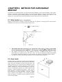
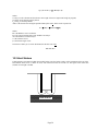
7.2 Arching
Arching effects are commonly applied in soil-structural interactions when the loads transfer from soil to structure or
vice versa. The rigid point receives more loads and the softer point receives fewer loads. Arching effects apply to
{Shoring} in three ways:
Horizontal Arching for lagging calculation: because the soldier pile is rigid and the timber lagging is flexible, the
uniformly distributed pressure is redistributed and reduced in the center span due to horizontal arching. This will be
handled in our lagging module. This arching does not apply to sheet pile walls.
Vertical Arching for apparent pressure envelopes: in a braced wall, the soil pressure increases at the brace location
and reduces mid-span between braces due to vertical arching. The redistributed pressures are called apparent pressure
envelopes. This is handled in the {EarthPres} module. Please see the {EarthPres} section of the manual for more
details. This arching does not apply to cantilever walls or one braced wall. Refer to <8.3 Apparent Pressure
Envelopes>.
Passive Arching for passive spacing below the base: when the soldier pile is pushed by active pressure and
loading, passive resistance is developed to counter the movement of pile. Thus a large area of the soil is mobilized.
The effective width is about one to three times the width of the shaft. For sheet piles, there is no arching, so the
passive arching spacing is 1. The following is the equation for passive arching spacing for soldier piles:
Passive Arching Spacing = Arching * D* n
Where:
D is the pile size. For drilled shaft and drilled-in, concrete soldier pile, D is the diameter of shaft. For driven pile, D is
the flange width.
Arching can be one of the following values
Dense sand: arching = 3
Medium dense sand and stiff silt: arching = 2*
Loose sand, soft silt, and all clay: arching = 1
* Arching=2 is recommended.
n is a multiplier, which is determined based on pile installation method: driving or drilling
For driven pile, n=1.5. Generally, driven steel piles have small flange width.
For drilled shafts filled with lean concrete or cement, n=1*
* For drilled shaft filled with gravel, the arching should be reduced based on soil conditions. n=0.5 for clay,
and n=0.75 for sand.
Page 31
.
.
.
.
.
.
.
.
.
Passive Arching:
1D: loose sand
silt, and
clay;
2D: Medium
Sand and silt;
3D: Dense sand.
Pile Spacing S
Soldier
Pile and
Lagging
D
Driving
Pile
X 1.5
D
Drilled
shaft
X1
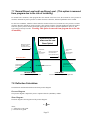
7.3 Vertical Bearing Capacity
Downdrag from
Ext. Force
Vertical loading
Shoring walls experience three types of vertical loading:
Down drag force from tieback anchors: if the angle of anchor
is large, the down drag force will be significant.
Vertical components from external force
Vertical components from active pressure: it is assumed that
the friction between soil and wall resists the vertical
components; therefore, this is ignored in the shoring
calculation.
Vertical loads at the top of wall. Engineers often use the wall
as vertical pile to support structural loading.
The total vertical loading transferred to the shaft below the base. If
there is not enough bearing capacity, the pile will settle. Therefore,
checking the vertical resistance capacity is important for a soldier pile
system with many tieback anchors.
Uplift from
Raker
Downdrag
from Tieback
Total Vertical Loading
Side Friction
Tip Bearing
F.S.=Vertical Capacity / Vertical Force
Vertical Bearing Capacity
Vertical Bearing Capacity Check
Vertical bearing capacity is determined by three components:
Tip resistance at pile tip
Side friction around shaft below base
Side friction between the pile and soil above the base: it is assumed that only the back face of pile is in
contact with the soil.
Users have to input allowable tip-bearing resistance and side friction to let program calculate the capacity. If the
capacity is not enough, the program will issue a warning and ask the user to increase pile embedment.
Sheet piles generally do not have a vertical capacity problem because of the large contact area between the
wall and the soil. The friction in the area can resist most of the vertical loading.
Page 32
.
.
.
Soldier piles with many tieback anchors need their vertical capacity to be checked due to the large down. the pile and the soil. The friction between lagging and soil cannot
drag force and small contact area between
.
be transferred to piles.
.
The requested embedment to support the vertical
. loading is calculated and provided by program.
.
Tip Resistance
= (Tip Area) * (Bearing)
.
Side Resistance = (Side Area) * (Friction)
Total Vertical Capacity = Tip Resistance + Side Resistance
F.S = Total Vertical Capacity / Total Vertical Loading.
Where:
Tip area – area of pile tip
Side area – Surface area of shaft below base and half of surface area above base
Bearing – Soil end bearing (user-input parameter), ksf or kPa
Friction – Friction between soil and shaft (user-input parameter) ksf or kPa
F.S. – Factor of Safety. If F.S. < 1, there is down-drag problem and the pile is passable to settle.
7.4 Embedment Calculation
Users are responsible to have adequate Factor of Safety (F.S.) in embedment based on project condition. There are
two ways to apply F.S. in embedment. One is input F.S. in Option page D., Item 15. It will reduce passive pressure
by dividing the pressure by F.S. Another way is increasing embedment length or total pile length based on calculated
embedment from program.
Cantilever Wall:
The program searches for an embedment to reach moment equilibrium, that the moment is balance at pile tip. For the
force equilibrium, there are different approaches in Shoring practices.
1. Some engineers suggest the force equilibrium is satisfied at the same embedment of moment equilibrium. There
is no additional increasing of embedment.
2. USS (Steel Sheet Piling Design Manual, Page 23, Simplified Method) suggests the embedment should be
increased by 20% to 40% to get the design embedment or so called force equilibrium.
3. AASHTO Standard Specifications suggest, first calculate embedment for moment equilibrium, then add safety
factor of 30% for temporary shoring; add safety factor of 50% for permanent shoring. The program provides 20%
increasing as in Results graphical pages, and then provides 20%, 30%, 40%, and 50% increasing in Report text pages.
The program gives users options to increase embedment based on above approaches (See Program Input Page D, Item
21). Users are responsible to check the project condition to select proper value. The default value is 1.2. Even
AASHTO calls the increasing as safety factor, users should not confuse it with Factor of Safety in Input Page B, Item
2, which is an additional FS for passive pressures. Some engineers think the compounding safety factors is
unnecessarily conservative and expensive.
Braced Wall:
Based on the last brace, the program searches for an embedment to reach moment equilibrium then determines the
brace force based on force equilibrium. Both moment and force equilibriums are satisfied. However, if the calculated
embedment is less than eight feet, the program will provide warning “ 5-10 feet is recommended”. In Shoring
practice, embedment should be at least 5 feet to prevent unexpected events and accident such as short pile, soft
ground, running water, construction error, boiling and heave…etc.
Fixed Embedment:
If there is an existing wall, or the pile length is limited, or an obstruction is encountered below the base, the
embedment is fixed and cannot be determined by program. The program gives the option of specifying a fixed
embedment.
1.
If the software determines that the request embedment is less than the fixed embedment, this required
embedment is used regardless of the fixed embedment. If you want to use an embedment, which is deeper than
request minimum embedment, you can apply a FS to the passive resistance in Page B, Item 2. Increasing the FS
until the calculated request embedment closes to the embedment you want.
Page 33
2.
3.
.
.
.
For a system with two or more braces,.the program will let the last brace take more loads from passive resistance
. be reached.
on pile embedment so that a solution can
.
For a one-brace or cantilever system, the
. program cannot shift passive resistance to the brace. If this is the case,
it will try to calculate a factor of safety
. of the system with reduced embedment. This is useful for evaluating an
existing shoring wall. If
.
the safety factor is low,
the system is not safe.
7.5 Limited
Penetration in
Rock
If bedrock is encountered and pile embedment
is limited, select [Fixed Embedment Option].
Adequate penetration in rock is required to
develop friction as shown in the drawings.
• If it does not meet the
requirements, select [No],
• If it is strong rock and meets
the requirements, select
[Unlimited],
• If it is weak rock and meets
the requirements, select
[Limited] and input rock
strength in the input box.
Quite often, when bedrock is
encountered, the pile cannot
be driven or drilled into
desired
depth.
Without
Bedrock
Bedrock
adequate embedment, the
system is not safe. However,
Drilled shaft requirement:
Driving steel pile requirement:
there is a solution to this issue
At least 1’ penetration in rock
At least 2-3” penetration in rock
if the pile can be driven 2-3
inches into the rock or the
Friction at Pile Tip
drilled shaft has at least one
foot of penetration into the
rock. Significant friction can
be developed to stabilize the shoring system. In this situation, the user has two options:
If the penetration into the rock is good, unlimited friction can be developed, and the program will thus be
able to determine the friction.
If the rock is weakened or soft, the penetration may meet the requirements, and users should input the limited
friction based on shear strength of rock. Units are in ksf or kpa
Note: This option cannot be used for cantilever walls, and should be limited in a one-braced wall.
7.6 Adding Ms for Embedment Calculation
When {Shoring} calculates the embedment, it takes the moment at the
last brace. If it finds a moment equilibrium condition, the search is
stopped and the embedment D is determined.
Some designs would like to add an additional pile moment capacity
into equation as show in the figure.
In this way, the pile embedment can be reduced. This is especially
important for cantilever wall. However, the embedment must be deep
enough in the soil to fully develop Ms. Generally, eight feet (2.4
meters) is the minimum requirement. Using Ms is not recommended.
If you do not know how to use Ms, Please do not apply Ms.
Ms is for someone with extensive shoring experiences. It needs a lot
of engineering experiences and judgment. Improperly using Ms
causes failure in shoring. There is no default value for Ms. It is based
on the pile you input. If Ms is used and the program finds the
embedment is too short, it will ignore or reduce the effects of Ms.
Page 34
.
.
.
. Low Brace Level. (This option is removed
7.7 Normal Brace Level and
.
from program due to the risk
. of instability)
.
For normal brace conditions, when program
. takes the moment at the brace level, the moment for active pressure is
clockwise. Moment for passive pressure is counter-clockwise.
Therefore, moment equilibrium can be reached.
.
For low brace conditions, when the software takes the moment at brace level, moment for active pressure is counterclockwise. Because moment for passive pressure is also counter-clockwise, moment equilibrium cannot be reached.
Therefore, passive pressure must be developed on the right side to achieve moment equilibrium. However, this
system may not always be stable. Warning: This option is removed from program due to the risk
of instability.
System may be not
stable with the Low
Brace Option!
Brace level above
the total active
force (above base)
Total active
force
(above base)
Total active
force
(above base)
Brace level below
the total active
force (above base)
Excavation Base
Total passive force
(below base)
Total passive force
(below base)
Total active force
(below base)
Low Brace
Normal Brace
Passive Pressure
Leveldeveloped in the Right Side.
Passive Level
Pressure developed in Left Side.
7.8 Deflection Calculation:
The deflection calculation should be started from pressure diagram.
Pressure Diagram
The pressure diagram is inputted by users or imported from the {EarthPres} module.
Shear Diagram:
The shear diagram is the integration of the pressure diagram.
V=
p dz
where,
V = Shear force at any point
p = Pressure at any point
Page 35
.
.
.
dz = Length segment for integration
.
.
.
Moment Diagram
.
The moment diagram is the integration of the shear diagram. The zero shear location is where the peak moment
.
occurs.
.
M = V dz
where,
M = Moment at any point.
Deflection Diagram
The deflection diagram is the double integration of the moment diagram. The first integration generates a slope
diagram, which is not shown in the report. The second integration generates the deflection diagram using the
following formulas:
(M/EI) dz
y = dz
=
where,
= Slope angle of curve
E = Elastic modulus of pile
I = Moment of inertia of pile
y = Deflection at any point
Note: Both the maximum deflection and the top deflection are given in the deflection diagram. For cantilever walls,
the maximum deflection occurs at the top of the wall, and thus equals the top deflection. Boundary conditions are
required to define the deflection diagram. In the program, it is assumed that the deflection is zero at the brace level.
The numerical integration above can be found in most structural textbooks. Deflection calculation for shoring walls
uses numerical processes. It is difficult to develop a single equation or formula to calculate the deflection of shoring
wall.
Numerical Solution
In the program, numerical integration is performed. Assuming the depth is D, which can be divided in to N segments.
The segment has length dz
For i from 1to N do integration at each point:
Z(i+1)=Z(i)+dz
V(i+1)=V(i)+p(i) dz
M(i+1)=M(i)+V(i) dz
(i+1)= (i)+M(i) dz /EI
y (i+1)= y(i)+ (i) dz
where:
Z(i) and p(i) are known. So V(i), M(i), (i), and y(i) can be calculated.
Deflection calculation for cantilever case - Point of Fixity.
For cantilever wall, the fixed point is about 1/2 to 2/3 of embedment. The program checks the passive
resistance and determines the point fixity. The results have been checked with many field measurements.
We found our deflections are a good match with the field measurements. If you get different deflection
Page 36
.
.
.
from other programs or methods, probably, the main reason is the different assumption of location of point
.
of fixity.
.
.
.
.
.
7.9 Pile Strength and Size
When the maximum moment is determined by the {Shoring} module, the required pile section modulus is calculated
by the following set of equations:
Page 37
.
.
. Sm = Mmax / Fb
.
Where:
. inputted ratio = 0.66)
Fb = User inputted ratio * Fy. (Typically User
.
Fb – Allowable bending strength
Fy – Pile yield strength
.
Mmax – Maximum moment of pile
.
Sm – Minimum section module
.
The program can automatically find a list of piles that meet the Sm requirement.
Sometimes, a pile will be designed with multiple sections; each section should meet the bending moment requirement.
Users can check the moment diagram or output data to find the moment distribution along the depth.
7.10 Single Span Beam and Continuous Beam
Users can let the software calculate moment as single span between braces. This will generate a large moment in the
middle of span and may be conservative. However, when the shoring is in the construction stage, the pile is
occasionally overstressed during over-excavation. This conservative approach can cover this overstressed situation.
In the final stage, users can calculate moment as Continuous Beam between braces. This will reduce maximum
moment by about 20%. This approach cannot be used for a cantilever or one brace wall.
Brace
Brace
Brace
Brace
Calculate moment as Continuous Beam
between braces:
Reduce Max. moment about 20%.
Not applicable for cantilever or one brace wall.
Calculate moment as Single Span
between braces:
Generate large moment.
This is good for stage construction.
7.11 Pile Buckling
Generally, design engineers do not consider pile buckling for the following reasons:
Soldier pile is confined by lagging that runs parallel to the wall. In the perpendicular direction, one side is supported
by the soil, and braces (struts or tiebacks) support the other side at a certain distance. Sheet pile is also supported by
soils and braces. Therefore, the program does not provide buckling calculation. However, if the tiebacks have a large
angle and generate large down-drag force, or there is vertical loading at the top of wall, pile buckling should be
checked.
Page 38
.
.
.
.
7.12 Step Wall Calculation.
.
.
Warning: CivilTech includes this .method as an option. There are no references about this
method. Civiltech does not provide
. any technical support and is not responsible for this
method.
The program can analyze step wall through the following steps. The active pressure from wall 1 is passed to passive
pressure of wall 1 and translated to wall 2 as additional active pressures.
Xc= 0.6(H2+D2) + 1.7D1
0.6(H2+D2)
H2
1.7D1
H1
Passive
Zone
Active
Zone
D1
Wall 1
D2
Wall 2
Step 1. Run Wall 1
Assuming there is no wall in front of Wall 1 and Wall 2
Use the {EarthPres}module based on existing soil parameters to find the active and passive pressure
Use the {Shoring} module to run wall 1 and find pile size and embedment D1
Step 2. Run Wall 2 and Find the Critical Distance: Xc=0.6(H2+D2)+1.7D1
Assuming there is no wall behind Wall 2
Run Wall 2 and find D2.
If X > Xc, Wall 1 does not have impact on Wall 2, so proceed to design Wall 2 without consideration of
Wall 1. If X < Xc, Wall 1 may have an impact on Wall 2, so go to Step 3
Page 39
.
.
.
.
Adjusted ground surface (remove soils behind Wall 1 )
.
.
.
.
.
Pp1
(1-X/Xc)Pp1
D1
Wall 1
Pa2
P2 = Pa2 + (1-X/Xc) * Pp1
Wall 2
•
Step 3. Find total Pressure for Wall 2
Use {EarthPres} to get active pressure Pa2 (Based on the adjusted ground surface)
Total pressure P2 is a combination of Pa2 and part of the passive pressure Pp1 from Wall 1: P2 = Pa2 + (1-X/Xc) *
Pp1
Step 4. Run Wall 2 again
Use {Shoring} to run wall to again and find pile size and final embedment D2.
Wall 2
H2
D2
Pp2
(1-X/Xc)Pp1
Pa2
P2 = Pa2 + (1-X/Xc) * Pp1
Notes:
If there are more walls below Wall 2, repeat the same steps for the next lower wall
Overall stability of the complete wall system should be checked.
Tiebacks are recommended in order to reduce the embedment of upper walls, thereby reducing impact on the
lower walls.
The bonded length of tiebacks should be placed outside the active and passive zone of the each wall.
The bonded length of tiebacks should be placed outside the failure plan defined in the stability analysis.
Surcharge pressure should be applied for each wall using the {Surcharge} module.
Earthquake load should be applied based on local conditions.
There is no reference. It has been used among shoring engineers. The method is recommendation
only. Engineering judgment is required to use this method.
Page 40
.
.
.
.
.
CHAPTER 8: METHOD
FOR THE EARTHPRES
.
MODULE
.
.
.
8.1 Flexible Wall and Rigid Wall
1. Flexible Wall - A wall body is flexible if it allows small movements, such as soldier pile wall and sheet pile
wall. Due to the wall movement, the pressure behind the wall is released from the at-rest pressure Ko to active
pressure, Ka. For gravity retaining walls, although the wall body is rigid, small rotation is allowed between wall and
soil, and thus these walls are also considered flexible. Active pressure should be used for design.
2. Semi-flexible Wall – Walls between flexible and rigid are called
semi-flexible walls. Small movement is allowed, but the movement is less
than that of the flexible wall. Active pressure, Ka, can be used.
2
3. Rigid Wall – A typical rigid wall is a basement wall. The wall body is
rigid, as the top and bottom of the wall are restricted by the floor and slab.
No movement is allowed. The pressure behind the wall is the at-rest Ko
condition.
Loading Control Movement– Users can control the wall movement
1
3
even though wall is flexible. For a flexible wall, if users apply Ko loading
to the design to reduce movement, the wall will have less movement. If
there are settlement-sensitive structures such as utilities or foundation
behind the wall, the users should select the at-rest Ko condition for soil
pressure, and select surcharge for rigid walls option for shoring design.
8.2 Ko and Ka Conditions
Ko is the at-rest condition. The soil pressure is higher than Ka. Using Ko implies that the wall cannot have any
movement. If there is a settlement-sensitive structure behind flexible wall, or if the wall is rigid, Ko should be used.
Ko = 1- sin
Ka is active condition. This implies that the soil behind the wall allows for small movements. Although it is suitable
for most shoring wall design, it should not be used if movement is restricted due to settlement-sensitive structures
behind wall.
Ka = tan2(45-/2)
8.3 Apparent Pressure Envelopes
Peck (1969) suggested using apparent pressure envelopes for shoring design. Apparent pressure envelopes are
converted from the total active force calculated from wedge or Coulomb’s analysis. For uniform soil, this value is
Eae= 0.5KaH2. A conversion ratio is involved in the conversion.
Conversion ratio = Total force of envelope / Total active force above base
Page 41
.
.
. walls or one wall
Triangular Envelope – For cantilever
.
braced with all types of soil. There is no agreement on one braced
. cantilever wall. The
wall, some designers only use triangular for
slope of the pressure equals Ka , which is.called equivalent fluid
. the slope below the
density. The slope may be different from
. Pressure, pa =
excavation base, if you have multiple soil layers.
. depth, and the total
KaH at base. The pressure increases with
H
active force (area of envelope) is 0.5KaH2. The conversion ratio
= 0.5KaH2 / 0.5KaH2 = 1.
Rectangular Envelope – For two or more brace walls with
sand. For walls with two or more braces, the pressure is shifted up
No Brace or One
due to vertical arching and preloading of braces. For sandy
Brace Wall
materials, the envelope is rectangular as shown in the second
All Types of Soil
figure. The slope in this case is zero. Pressure, pa = 0.65KaH.
The total force (area of envelope) is 0.65KaH2, which is 130% of total active force above base. The conversion ratio
= 0.65KaH2 / 0.5KaH2 = 1.3.
Trapezoid Envelope 1 – For two or more brace walls with soft to
medium clay. For walls with two or more braces in soft to medium
clays, the trapezoid envelope is recommended. Pressure, pa = KaH.
Based on Trapezoid Envelope shape, the total force (area of envelope) is
0.875 KaH2. The conversion ratio = 0.875 KaH2 / 0.5KaH2 = 1.75.
H
Trapezoid Envelope 2 – For two or more brace walls with stiff clay.
There are two slopes at the top and bottom, at 0.25H distance,
Pressure, pa = 0.8KaH. Based on Trapezoid Envelope shape, the total
force (area of envelope) is 0.6KaH2. The conversion ratio = 0.6 KaH2 /
0.5KaH2 = 1.2.
Note: The above ratio is default in program. Users can input own
values such as shape (for example, change 0.25H to 0.2H) and ratio in
option page.
Braced Wall
Majority of Soil is
Sand and Silt
0.25H
0.25H
0.5H
0.75H
Braced Wall
Braced Wall
Majority of Soil is
Soft to Medium Clay
Majority of Soil
is
Stiff Clay
Page 42
0.25H
.
.
.
.
.
.
.
.
.
8.4 Method of Earthquake Analysis
For temporary shoring walls within less than a one-year lifetime, it is not necessary to apply earthquake loading. For
permanent shoring walls or walls with a life longer than one year, earthquake loading should be considered.
The program applies two additional earthquake forces, KhW and KvW, in the wedge analysis. W is the weight of the
wedge, Kh is horizontal earthquake acceleration coefficient, and Kv is vertical coefficient. A typical value of Kh
would be 0.3. This means that the earthquake acceleration is equal to 0.3g. Kv is usually Kh multiplied by 0.5.
In active conditions with single granular soils, the wedge analysis generates results that match up with the results from
the Mononobe-Okabe equation. The Mononobe-Okabe equation is shown below:
Page 43
.
.
.
.
.
.
.
.
.
Reference: DEPARTMENT OF THE ARMY EC 1110-2-6058 US Army Corps of Engineers
If there are multiple soil layers or cohesion, the Mononobe-Okabe equation will not work; users should take
advantage of the wedge analysis.
The program generates an additional trapezoid earthquake pressure diagram above the base, which has a total force of
0.6H from the bottom of the wall. Below the base, the earthquake loading is included in the active and passive
pressures. Earthquake loading increases active pressure, but reduces passive pressure.
Generally, earthquake loading should apply to both active and passive pressures. Some designers and regulations only
require applying the earthquake loading to active pressures. The program provides the option of only applying
earthquake loading to the active pressures. If there is no earthquake loading, the equations above are the same as
Coulomb’s Method.
8.5 Soil Parameter Screen and Relationship
Because of the wide variations of soil and site conditions, the soil parameters should be determined on the basis of
field exploration and laboratory testing. However, for preliminary designs or a lack of data, it is often necessary to
presume appropriate soil properties based on limited information. The program provides relationships between each
property for shoring analysis. The relations are based on the following table (after Terg and Navdocks)
General Soil Parameters for Sand
Compactness
SPT*
Relative Density
Friction
Unit Weight
Moist
Submerged
Very Loose
Loose
Medium
Dense
Very Dense
Dr
Unit
-%
Deg
0-4
0-15
<28
4-10
15-35
28-30
10-30
35-65
30-36
30-50
65-85
36-41
>50
85-100
>42
pcf
pcf
<100
<60
95-125
55-65
110-130
60-70
110-140
65-85
>130
>75
Symbol
N SPT
*SPT -- Standard Penetration Test
Reference: Steel Sheet Piling Design Manual, USS, 1975, p.12
Page 44
Consistency
SPT
UCS*
Shear Strength
Unit Weight
Saturated
.
.
. Soil Parameters for Clay
General
.
.
.
.
.
.
Very Soft
Soft
Medium
Stiff
Very Stiff
Hard
Symbol
NSPT
qu
Cu
Unit
-pcf
psf
0-2
0-500
0-250
2-4
500-1000
250-500
4-8
1000-2000
500-1000
8-16
2000-4000
1000-2000
16-32
4000-8000
2000-4000
>32
>8000
>4000
pcf
<100
100-120
100-130
120-130
120-140
>130
*UCS -- Unconfined Compressive Strength
Reference: Steel Sheet Piling Design Manual, USS, 1975, p.12
8.6 Cohesion in Shoring Analysis
Generally, cohesion is not recommended in shoring design. Field experience indicates that:
Cohesion is not reliable. A vertical cut can stay for a few days but will collapse after some time
Tieback in the clay will creep
If there is a small amount of sandy in the clay, the failure will go through the sand. Therefore, a small
amount of sand controls the failure
When water intrudes on the clay, the strength of the clay will reduce significantly
The property obtained in the field is undisturbed. During the excavation, the clay will be disturbed. The
strength of the clay can be changed significantly
Based on cohesion calculations, the active pressure can be zero or negative. This, however, is a short
phenomenon. The pressure will increase when water intrudes or time-creep occurs
Equivalent Clay
Based on the above reason, we suggest avoiding use cohesion in shoring design. A soil type called Equivalent Clay is
provided in Soil Parameter Screen. In this type of soil, cohesion is converted to equivalent friction for shoring design.
Users should select this type for clay and silt. The conversion is based on that two soils have the same field strength:
N (SPT) value. The conversion: C -> N, then N -> Phi. The converted soil only has phi and C=0. C to N and phi to
N relations are in above table (USS sheet pile manual page 12, table 2 and 3).
If you still want to use C, manually calculate the pressures and directly input in Shoring Module.
8.7 Earth Pressure Analysis
Wedge Analysis
Active analysis assumes that the
wall moves away from the soil
mass. The soil starts to fail in a
straight line. Wedge analysis tries
to find maximum force between all
the failure lines. Passive analysis
assumes that the wall moves
against the soil mass and the soil
starts to fail in a straight line.
Wedge analysis tries to find the
minimum force between all the
failure lines. Before computer
became available, engineers had to
draw lines on paper for the wedge
analysis. This is called the
Culmann
method.
Using
a
computer, the analysis is much
easier than before.
Page 45
.
.
.
.
.
.
Coulomb’s Method:
.
It is a special case of wedge analysis when the soil is made out of granular material and is uniform. The limitations of
.
Coulomb’s equation are:
Slope is infinite and the slope angle. must be smaller than friction angle.
Only for granular material, no cohesion
The equations used for Coulomb’s Method are presented in Section 8.4.
Rankine Method
It is also special case for Coulomb’s method when surface is flat and there is no wall friction.
Active Pressure Analysis
Passive Pressure Analysis
Page 46
.
.
.
.
.
.
.
.
.
Log Spiral Analysis
Although the actual failure line in the soil is somewhat different than the assumed straight line, the results do not
differ greatly. However, in the case of passive pressure, when the wall friction increases, the straight line increases the
passive pressure values. The high passive pressure values could lead to unsafe conditions, so the Log spiral failure is
suggested for walls with large values of friction as shown in figure.
Page 47
.
.
.
8.8 Numerical Method vs. .Equation Method:
The numerical method is used in the program
. for wedge analysis and log spiral analysis. Using the numerical method,
the user can calculate:
.
Complicated surface, subsurface conditions
.
Different water tables
.
Multiple layers of soil
.
Soil with cohesion
The numerical method breaks depth into many small segments and calculates the total active force at each depth.
Through deviation operation, the soil pressure is generated. Because of the deviation, the results may generate some
errors:
The soil pressure gradually changes from one soil layer to another. There is no sharp change as in Coulomb’s
equation. However, it is probably true to the actual soil pressure in the field.
When pressure slope has significant changes, some spike or noise may show up in the results
When soil changes from cohesive changes to granule material or vise versa, some errors may occur in the
interface of two layers.
For large cohesion, search may not be able to find the maximum active force or minimum passive force.
If the above situation occurs, the pressure generated by the numerical analysis may look stranger. Therefore, the
equation method should be used.
The equation method, such as Coulomb’s equation, has limitations, such as:
Slope should be infinite. The slope angle cannot be larger than the friction angle
Only for granular materials, no cohesion
Users should try the equation method first, then the wedge analysis. Log spiral is used only if the wall
friction is large.
8.9 Water Table and Seepage
Concrete
Seal at
Excavation
Base
Actual
Pressures
User Input
Depth
such as
bottom of
Lagging
Net
Pressure
1. No Seepage
2. Seepage at Wall Tip
3. Seepage at User Depth
Page 48
4. Seal at Low Water Table
.
.
.
Sheet Piles and Slurry Walls are considered as water cutoff walls. It only allows water to flow below the tip. Soldier
piles and secant pile walls allow water flow.below the excavation base. There are different categories:
.
.
No seepage at wall tip
.
If the soil is impermeable, such as clay, the water cannot flow freely from one side to another side. A large net
. of two sides are not equal.
pressure is built up at the active side. The pressures
.
Seepage at wall tip
For the cut off wall, when the wall tip is in permeable granular soil, the water can flow freely from one side to another
side. The pressures at the wall tip are equal for both sides as shown in the drawing.
Seepage at depth other than wall tip
For some shoring walls, the cut off depth is not at the pile tip. For example, plate or sheet pile is used as cut off panel
between the two soldier piles. The cut off panel does not reach the pile tip, it only reaches to certain depth below the
base. Users can input the depth.
Concrete seal at excavation base
The hydraulic pressure will build up below base. The seal should have enough weight to resist the pressure with an
appropriate safety factor. Sometimes, sump drain is used to release pressure.
Page 49
.
.
.
.
.
CHAPTER 9: METHOD
FOR SURCHARGE
.
MODULE
.
. various surface loadings as well as the soil behind it. These surface
The function of a retaining structure is to retain
loadings, or surcharges, generate lateral pressures
. on the wall, which contribute to the active pressures that tend to
move the wall outward. Typical surcharge loadings come from railroads, highways, buildings, piles, cranes, etc. The
loading cases of particular interest in the determination of lateral soil pressures are described below:
9.1 Strip Loads (Wayne C. Teng Equation)
Highways and railroads are examples of strip loads. When they are parallel to a shoring wall, the lateral pressure
distribution on the wall may be calculated using the figure below.
H =
2 Qs
[ - sin cos2 ]
The middle dash line in drawing is at central line of the angle, . Many people think
it is at central point of the width W/2. It is incorrect, which generates different result.
This equation is developed by Dr. Teng published in his paper: “Foundation Design, Wayne C. Teng,
Prentice-Hall, Inc., Englewood Cliffs, New Jesey, 1962”. It is based on Boussinesq equation and modified
by experiment. Boussinesq equation is an elastic solution. Teng equation is considered as plastic solution.
The equation is widely used in shoring design and is well accepted by shoring engineers.
9.2 Area Loads
Buildings and large equipment are typical area loads. When they
are placed near a sheet pile wall, the lateral pressure distribution
on the wall can be calculated as shown in the figure below. The
lateral pressure due to an area load can be calculated by using
integration of Boussines equation (Reference: Poulos & Davis,
“Elastic Solutions for Soil & Rock Mechanics”, Page 54).
However, the Boussines equation is an elastic solution, which
generates a relatively higher lateral pressure. Since soils are
plastic materials, we think Teng Equation for strip loading is
more suitable for the shoring calculation. Therefore, a length
factor is added to Teng Equation for area loading calculation.
When the length (L) is infinitely long, the equation is the same
as that for strip loading.
Page 50
Parea = f * Pstrip
Where f is length factor:
f = 1- 1/(0.25 * L/(X+1) +1)
.
.
.
.
.
.
.
.
.
L - length of area loading; X - Distance to the wall.
When L is infinite, f = 1, Parea=Pstrip
We plotted curve from Boussinesq equation and use this curve to scale down to fit Wayne C. Teng Equation.
Then we get the above equation.
9.3 Line Loads
A continuous wall footing of narrow width or similar load parallel to the retaining structure may be taken as a line
load. In this case, the lateral pressure increases from zero at the ground surface to a maximum value at a given depth
and gradually diminishes at greater depths. When the width = 1 (foot or meter), The strip load become line loading.
9.4 Point Loads
The lateral pressure distribution on a vertical wall due to a point load may be calculated as shown in Figure below.
When L=1 in Area Loading Equation,
f = 1- 1/(0.25 *1/(X+1) +1)
Ppoint = f * Pstrip
9.5 Infinite Loads
The infinite loading has two options:
1.
Conversional active or at-rest method. It is based on active failure analysis. This option 1 is recommended.
p= Ka q
as active pressure. It is for flexible wall
p= Ko q
as at-rest pressure. It is for rigid wall
p= (Ka+Ko) q /2
semi-rigid wall
It is for
X
2.
Strip loading method as descript in Section 9.1,
where Loading Width = infinitive.
This option gives much higher
pressure. Because it is
originally from an elastic
solution, even modified by Dr.
Teng.
Page 51
E-80 COOPER
RAILROAD LOADING
.
.
.
.
.
9.5 Railroad Loads
. Cooper loading. On the figure below, X is calculated as the distance
The railroad load is for standard E-60 and E-80
.
from the wall to the center of the railroad track. The locomotive weights of 520 metric tons and axle loads equal to 37
.
metric tons (80 kips). The load is acting on two tracks 9 feet apart. The axle spacing is 5 feet. The vertical surcharge
. and E-80, A rigid wall option is automatically selected in Item 3 of Wall
is 80/(5’x9’) = 1.778 ksf. For standard E-60
Condition in Input Page A. The calculation equation is the same as the one used in < Section 9.3 Strip loading.
Please note: X of Strip loading is from wall to the nearest edge of the strip load. Therefore, if users check it with Strip
loading, the Xstrip = Xrail–9/2 = Xrail-4.5. Width = 9. q = 1.778 ksf.
The railroad load option of the program assumes 9 feet as railroad ties and use q =80/(5’x9’) = 1.778 ksf.
If you use 8.5 feet as railroad ties. q =80/(5’x8.5’) = 1.882 ksf. You need to use strip load option and input
q=1.882ksf.
W
a
9.6 Flexible and Rigid Walls
l
Wayne C. Teng Equation is based on Boussinesq equations, which gives higher pressures due to following
reasons:
l
1. Boussinesq equation is elastic solution. Soil is plastic materials.
2. Boussinesq equation assumes half space condition and ground does not move. But in flexible wall condition the
ground moves under lateral pressure. After the movement, the pressures are partially released.
3. Field measurements indicate Boussinesq equation give 50% higher pressures.
4. The shoring design is based on failure analysis. Ka (active coefficient) is used instead Ko (at-rest coefficient).
Ka is used for determination of the active pressure for flexible wall condition.
Ko is used for rigid wall condition (at-rest condition).
Commonly, Wayne C. Teng Equation is used for rigid wall condition.
It can be reduced about 50% to match Ka pressure for flexible wall condition.
In the program, the calculated pressure of flexible wall gets 50% of the pressure from rigid wall. The calculated
pressure of semi-flexible wall gets 0.75 of the pressure from rigid wall. The 50% deduction for the flexible wall is
from shoring practices. There is no reference. The program provides it only as an option. Users are
responsible to use 50% deduction.
Page 52
.
.
.
.
.
CHAPTER 10: METHOD
FOR HEAVE MODULE
.
Most of the time, heave happens in clay or. sandy clay soils. For clay, the method developed by Bjerrum and Eide
(1956) can be used; for sandy clay and clay. with sand, Terzaghi’s method (1943) is suitable. Bjerrum’s method only
considers cohesion while Terzaghi’s method
. considers both friction and cohesion of the soils. Users should use their
own judgment to determine which method is more suitable for situation in the field. In {Heave}, only Terzaghi’s
method is used.
10.1 Terzaghi’s Method
The method of heave analysis was proposed by Terzaghi. The method was used for trench excavation. It also can be
used for soldier pile wall. People use this method for sheet pile wall and ignore the resistance from sheet piles.
Both the friction angle and cohesion of the soil are given. It can be seen that the proposed failure is defined by the
sliding surface bce.
According to this theory, the factor of safety against heave is
Factor of Safety (FS) = Resistance Force / Driving Force
Where the driving force is the force that pushes soil block abcd downward. It includes the weight of this block and
surcharge on top. This is expressed as:
Fdrive = Wabcd + q B1
Where:
Wabcd is the total weight of abcd
q is the surcharge applied on the surrounding ground surface—ab.
B1 is the distance of ab.
B1 = B /
B is the width of excavation.
B
B1
a
q
b
F
W
e
d
c
Bearing Soil
qu
Resistance force is formed by the friction along the failure line and the bearing capacity of the base soil under dc,
which is calculated by Meyerhof’s modified bearing equation (Das, 1990).
The resistance force R is calculated using the following formulae:
R = q u B1 + F
Page 53
.
.
.
q = (C N F ) + (' B N F /2)
.
.
.
Where:
C and ' are the cohesion and the effective.unit weight of base soil (Input total weigh in program)
N and N are the bearing capacity factors .
F and F are the shape factors
.
And F is the friction force along the possible failure plane of bc, which can be expressed as:
u
b
b
c
q
cs
rs
b
c
cs
b
1
q
rs
F = (c dz) + (Ka Pv tan dz)
Where:
Ka is the Rankin’s active coefficient.
Pv is the vertical earth pressure at the middle of each layer.
dz is the thickness of each soil layer.
c is the cohesion of soil.
is the friction angle of soil.
The Factor of Safety (F.S.) can be determined for the base soil of dc.
FS = R / Fdrive
10.2 Hard Stratum
If hard stratum is encountered within the possible failure zone, the failure surface will be terminated at the top of the
hard stratum where heave is unable to occur, and will thus increase the overall F.S. The figure below shows this
situation for Terzaghi’s method.
.
Hard Stratum
Page 54
.
.
.
.
.
CHAPTER 11 QUESTIONS
& ANSWERS
.
.
I cannot change printer
.
For some Windows operation system, you can't change printer within program.
.
If you want to change printer, you need to do followings:
1. Close the program.
2. In Windows, click Start; go to Setup, Printers & Devices
3. Select the printer you want, make it default printer. Close the panel.
4. Open the program again. Then send to print.
How to make a PDF file?
You need to install PDF writer such as Adobe PDFwriter (or CurePDF, DoPDF). It is installed in your computer
as one of your printers. To print PDF file, you need to do followings:
1. Close the program.
2. In Windows, click Start; go to Setup, Printers & Devices
3. Find the PDF writer you installed before, make it as default printer. Close the panel.
4. Open the program again. Then send to printer. The PDF write will ask you where to save the file. Input the
path to save the PDF file.
Input Error
If you are in a country other than US, you may use decimal symbol “,” instead “.”
Our software must use "." for decimal symbol.
You need got to Windows Control panel, Open "Regional and Language Options"
Select Number Tab, change Decimal symbol from “,” to "."
Buttons in input screen shifted or not aligned
For some computers, the buttons may not be aligned with column in the table. You may do followings to
improve it:
1. Go to Windows Control Panel,
2. Open Display,
3. Try different Screen resolutions and Fonts size. Most of time, you can fix the problem.
How the program convert Nspt to other soil parameters?
The program used Section 8.5 from Nspt to get the other soil parameters.
Does Nspt need to be corrected?
Yes. You need to input corrected SPT such as N1. If you only have field SPT, it is OK to use them directly,
because the conversion is based on statistic data. It is not so accurate.
Under the slide ruler, the N value only up to 60. How to account for N > 60.
References only can find correlations between N and phi, C, unit weight up to N=60, If N>60, Users can
directly input phi, C, and unit weigh based on lab testing or local experiences. Actual, N above 60 does not have
too much meaning (SPT method is back 70 year old and very rough). Randomly encountered, large gravel, rock
pieces, or cobblestones can increase N significantly. Lab tests such as unconfined compression test provide
more meaningful data.
How to apply Load Factors and Factor of Safty?
In Surcharge module, apply Load Factor in Page A, Item 4.
In EarthPres module, apply Load Factor in Page E, Item 4-7.
In Shoring module, apply Load Factor in Page B, Item 1.
Please note, the Load Factor in Shoring is duplicated with Load Factor in EarthPres. You only apply it in
one place. Please do not apply it twice.
Page 55
.
.
.
There is also a Factor of Safety in Shoring module in Page B, Item 2. For temporary wall, FS =1 to 1.3 is
. 1.5 is recommended.
recommended. For permanent wall,
.
.
How can seismic condition be considered
in analysis?
.
In EarthPres module, input acceleration form local building code. Earthquake pressure is based on Mononobe-Okabe
.
method.
.
How to handle a force at wall top?
You have to way to input. 1. Input a force in Page C, Item 5 of Shoring. 2. Apply a pressure equals to the force in
Page B, Item 1. For example, Z1=0', Z2=1', P1=1ksf, P2=1ksf, Spacing = 1' (for sheet pile, in Page A, Item 4). It is
equal to a force 1 kip per foot. If Spacing = 8' (for soldier pile), the force will be 8 kip for each pile. For a force is
toward the wall, input P1, P2 negative value.
How to input Ms (item 12 in Page D, Option page, Shoring)?
Please see Page 7.2-103 of DM7 for Ms. Using Ms is not recommended. If you do not know how to use Ms, Please do
not apply Ms. Ms is for someone with extensive shoring experiences. It needs a lot of engineering experiences and
judgment. Improperly using Ms causes failure in shoring
How to handle Rock at bottom?
You need to use at least one brace. For cantilever wall, the shoring system is not stable. You can handle the case with
two options:
1. Select Option 3 in Item 9, 10, 11 in Page D.
Input a fixed embedment and friction between rock and pile tip.
2. Directly input a large passive resistance for rock layer in Page B, Item 2. Typical value: Z1 -Top of rock, Z2 bottom of rock, P1=P2 = 3ksf to 5 ksf.
Does the program apply Rowe Reduction?
No Rowe Reduction applied. You can apply it after program gives maximum moment,
If the existing wall has embedment less than program required minimum embedment?
For cantilever wall, the fixed embedment should be longer than the required minimum embedment. Otherwise, the
wall is not stable. If the existing wall has been there for a long time, the active pressure inputted may be too
large. You can reduce the active pressure by input a factor <1 in Item 1, Page B.
If the wall has embedment more than program required minimum embedment?
If you have fixed embedment longer than required minimum embedment, the program only uses the minimum
embedment. Because the program is based on the passive pressure you inputted. you can redistribute the passive
pressure by inputting a FS > 1 in Item 2 of Page B. The passive pressure will be redistributed and the embedment
increases. Increasing the FS until the calculated minimum embedment = fixed embedment.
Page 56