1
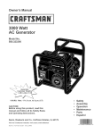
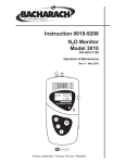
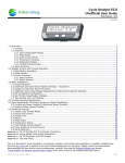
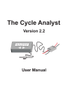
The Grin Cyclery
1 of 8
http://www.ebikes.ca/store/store_CAV3.php
"Thinking Outside the Four Wheeled Box"
ebikes.ca
Home
Store
FAQ
Simulator Spoke Calculator Cycle Analyst Info Lights Info Torque Arm Info Troubleshooting
Projects Events Contact Us
Purchasing & Shipping Info
Conversion Kits
Parts
Batteries
Controllers & Throttles
Cycle Analysts
Lights
Motors
Misc. Parts & Connectors
Unicycles
View Cart 0
Search
Temporary CA V3 purchase page
This is a purchasing and info page for Beta Models of the V3 Cycle Analyst, as well as the compatible THUN torque
sensing bottom brackets. The story of this project is largely covered in the Endless Sphere thread beta announcement
here: http://endless sphere.com/forums/viewtopic.php?f=4&t=37964
In a nutshell, the V3 device may interest you if you want to add a torque sensing bottom bracket to your bike, if you
have a motor that can make use of temperature monitoring and thermal rollback, or if you have a powerful setup that
can benefit from advanced throttle controls, or if you just like to play with handy gadgets. If these features are not
required then the recently upgraded and less expensive V2.3 Cycle Analyst would be more suitable.
Beta Product
The V3 Cycle Analyst is currently in its very last beta state and all of the planned software functionality has largely
been finalized with the B20 code. Even so, please be aware of the following points:
You will want to have the ability to reflash the firmware as new updates or possible bug fixes are released. Any
serial port adapter with a 0 5V TTL output will work if you are familiar with that stuff. We also offer a USB >TTL
adapter cable with the correct terminals, which you can also get direct from FTDI:
Though there are no known issues in the current code, it is possible for as yet undetected bugs in the code to
cause the CA to freeze in a state where the throttle output is driven high. If you are using the CA as your
controller throttle input, be sure to have a user accessible kill switch to cut power in this scenario.
There is no supporting documentation other than what is on this page and the previously listed endless sphere
thread. A full fledged user manual will still take quite a while for us to produce.
V3 CA Device and Accessories Store
Serial
Description
CAD
Price
|
USD
(Click for
details)
$150.00 USD
CA3 DP
Version 3 Direct Plug Cycle Analyst
CA3 DPS
Version 3 Direct Plug Cycle Analyst with separate
Speedo Cable, for geared or mid drive motors
CA3 USB
TTL >USB cable for flash firmware reprogramming
and data logging
In Stock
$155.00 USD
In Stock
$22.00 USD
In Stock
11/22/2012 11:31 AM
The Grin Cyclery
2 of 8
http://www.ebikes.ca/store/store_CAV3.php
$375.00 USD
CA3_TorqueKit
Package of THUN torque sensor, CA V3 DPS, CA3
Stand Alone Shunt, and CA USB Cable, for adding
pe...
Shunt CA3
Molded 1mOhm shunt with pass thru of throttle and
speedo wires for 3rd party controller integration
In Stock
$40.00 USD
In Stock
$195.00 USD
THUN_120K
Thun X CELL RT Torque Sensor, 120K/116mm
Spindle, with connector cable to V3 CA
THUN_120L
Thun X CELL RT Torque Sensor, 120L/119mm
Spindle, with connector cable to V3 CA
THUN_136L
Thun X CELL RT Torque Sensor, 136 mm Spindle,
with connector cable to V3 CA
In Stock: 12
$195.00 USD
In Stock: 68
$195.00 USD
In Stock: 7
For those wanting to use the proportional pedal assist functionality and/or look at human power watts and pedal
cadence, we have the THUN torque sensors left in the 3 different spindle lengths above. They work with 68mm threaded
bottom bracket shells and are only available for square taper cranks. For dimensional diagrams, see the Thun cartridge
length specifications.
Firmware Programming
The CA firmware is updated via the communications port. You will need to download and uncompress the following
uploader program and launch the file "CAFirmareUpdateTool.exe":
Download CA V3 Update Tool, V1.1
As well, you will need the programming cable to be recognized as a COM port on your computer. Windows XP and
Windows 7 will both find the correct driver automatically if you enable it to search windows update, otherwise you can
download and install the VCP (virtual com port) drivers from FTDI:
http://www.ftdichip.com/Drivers/VCP.htm
In order for the bootloader to work the Cycle Analyst must be externally powered up, it won't get power just from the
programming cable alone. So either bring a laptop nearby to your ebike, or have a battery or other source at hand to
turn on the CA.
To update the firmware, select the .hex file you want to load, select the serial COM port on your machine that is
connected to the CA, and then hit the button "Update Firmware".
11/22/2012 11:31 AM
The Grin Cyclery
3 of 8
http://www.ebikes.ca/store/store_CAV3.php
At that point, the program will say "Please cycle power to the device" and it is waiting for the Cycle Analyst to be turned
on. Or, if the CA is already powered up, then it is waiting for you to turn it off and then on again. You have 30 seconds
in which to turn on the device, and once that happens the Cycle Analyst will be detected and you will see a message
showing the firmware upload progress, followed by a verify process, and finally an "Upload Complete!".
The current firmware release is Beta20, which is also bundled in the updater utility download. This will work fine for any
devices currently programmed with Beta16 or later firmware. If you have a way old unit with Beta15, then you will first
need to program with the CA3B19 file below, and then after that with the B20. :
CA3 Beta20 Hex File
CA3B19 Hex File
Connector Pinout
The V3 CA device has a cable bundle bringing out all the signal wires into suitably terminated JST SM plugs. The
following shows the standard CA V3 wiring harness connector details for all cables coming out of the V3 CA:
Pad Descriptions
The following shows the solder pad locations on the circuit board itself, for anyone who is doing their own custom wiring
harness directly into the Cycle Analyst enclosure:
11/22/2012 11:31 AM
The Grin Cyclery
4 of 8
http://www.ebikes.ca/store/store_CAV3.php
Explanation of Top Row Accessory Pads
Throttle In (Thi): This is the input signal for the user throttle. It can accept signals in the range of 0 5V. When
no throttle is attached, the signal will be pulled down to 0V.
Temperature Probe (NTC): This is the input for a temperature signal. The pad has a precision pull up resistor to
5V, so it can be used with a simple 10K NTC thermistor between the pad and ground. Alternately, an actively
driven signal from 0 5V (such as from an LM35 type IC) can be fed to this pad and scaled linearly into a
temperature reading
Auxiliary Input (Pot): The purpose of this input is to allow on the fly adjustments of one of the CA's limit values
(ie the current limit, speed limit, or power limit). That can be accomplished either via a potentiometer, or for
discrete settings with a multi position switch and resistor dividers. A 0 5V signal range is allowed, and it defaults
to 5V if left disconnected.
Digital Ebrake (EBK): This input has an onboard pull up to 5V to be used with an ebrake cutoff switch. When
the signal is shorted to ground, the CA thinks that your brake levers are depressed and forces the CA's throttle
output to 0V.
10V: This is an output pad specifically for supplying power to the THUN torque sensing bottom bracket. It can
potentially be used as a low current power source by other PAS sensors too, however care must be taken as this
supply is not fused or protected, and a short to ground will damage the CA. Current draw from this line should be
limited to 15mA max and only with 48V or lower batteries.
Pedal Sensor Input (RPM): This is a digital input for a pedal cadence sensor. It has an onboard pull up resistor,
so it can work with an active hall effect device or a simple magnet and reed switch pickup.
Pedal Direction Input (Dir): This is used to distinguish between forwards and reverse pedal rotation for PAS
sensors that provide this signal. It can support both a pure direction signal (eg 5V = fwd, 0V = reverse), or a
quadrature type encoder such as on the THUN sensors.
Torque Sensor (Trq): This is a 0 5V input for a torque signal. The human pedal torque can be measured either
via a torque sensing bottom bracket (THUN, FAG), or via a DIY tension meter on the bike chain itself. The torque
signal here is multiplied by the calculated pedal RPM signal to derive the human power on the CA, and to provide
proportional torque assist.
External Voltage Sense (Vex): The purpose of this pad is to allow for sensing high voltage batteries without the
danger of bringing a high voltage line up to the Cycle Analyst. The external battery must be scaled down to a
0 5V range, and this will allow up to a 500V voltage display range on the CA (as determined by the V/V VSense
value in calibration).
Serial Receive (Rx): This is a 0 5V TTL input signal for serial data communication into the CA used for reflashing
the firmware.
Serial Transmit (Tx): This is the 0 5V TTL serial data transmission line. It outputs a steady stream of info (9600
baud, 8 bit) for datalogging purposes, and is also used by the bootloader to verify flash updates.
Explanation Standard CA2DP Pads
Negative Shunt Sense Lead (S2): Connects to battery side of shunt, must be within 0.5V of Gnd
Positive Shunt Sense Lead (S+): Connects to controller side of shunt, must be within 0.5V of Gnd
Throttle Over2ride Output (Thd): This is the same as the Throttle output (ThO) after passing through a diode.
It is used for legacy V2 style CA connections where the CA is only used to pull down a separate throttle signal.
Throttle Output (ThO): This is the direct throttle signal from the CA, which can be connected directly to a
controller throttle input line.
Speedo Pulse Input (Sp): Can be wired up with a reed switch and magnet speedometer sensor, or connected
directly to one of the hall signals in a direct drive motor.
Battery Power (V+): This is the V+ supply of the battery pack, used both to power the CA and also to sense the
battery voltage. The maximum supply voltage with no accessories is 150V, but this must be derated if there are
11/22/2012 11:31 AM
The Grin Cyclery
5 of 8
http://www.ebikes.ca/store/store_CAV3.php
other devices (Torque Sensor, Input Throttle etc) also drawing power from the CA.
Setup Menu Details for Beta20 Firmware
The setup menu is accessed by pressing and holding the left button for several seconds, or by holding the right button
down while the CA is powered up. It is a 2 level deep menu list organized into 13 high level categories to let you adjust
over 60 different settings:
1. SETUP SPDOMETER
Preview line shows current units (mi/km), current wheel size (in inches), #Poles, and the state of the speed
sensor input (up arrow = 5V, down arrow = 0V)
a. Units: Select between using units of kilometers or miles. Notice that changing this will not rescale
odometer, speed limits etc.
b. Circuf: Exact wheel circumference in mm.
c. #Poles: This is the number of pulses on the Sp pad that is considered one full wheel revolution. For direct
drive hub motors with a CA DP model, it would be the number of magnet pole pairs in your hub (usually
between 8 to 23). If you have a CA DPS with external speed sensor, it would be the number of magnets on
your wheel, usually 1, but for better low speed control it can be advantageous to put several magnets on.
d. TotDist: Lets you pre load the odometer.
2. SETUP PRESETS
Preview line shows number of mode presets (1, 2, or 3), and number of batteries (also 1, 2, or 3) which are
enabled.
a. Preset Cnt:
i. Only 1: Effectively disables mode presets.
ii. 1&2 Enabled: Allows you to easily toggle between two distinct sets of CA limit settings.
iii. 1,2&3 Enabled: Allows you to setup and toggle between 3 distinct CA limit settings.
b. Preset #1 Name: Lets you select a name for the 1st CA preset. There are currently seven names to choose
from (ex: Economy, OffRoad, Assist, etc.) and suggestions for more are welcome. Assigning a name does
NOT preload any particular set of limit values, so you will still need to manually input the various current,
speed, power limits, throttle and PAS mappings that you want for each preset.
c. Preset #2 Name: Lets you select a name for the 2nd CA preset (ex: Economy, OffRoad, Assist, etc.). This
option only shows up if you have at least two mode presets enabled.
d. Preset #3 Name: Lets you select a name for the 3rd CA preset (ex: Economy, OffRoad, Assist, etc.). This
option only shows up if you have all 3 mode presets enabled.
e. Crnt Prset: Select which of the 3 possible presets is currently active.
f. Batteries?:
i. Batt A only: Only one battery pack setup
ii. Batts A&B: Allows you to easily toggle between two different battery packs.
iii. Batts A,B,C: Allows you to choose between 3 different battery packs.
3. SETUP BATTERY
Preview line shows nominal voltage and chemistry of selected battery pack.
a. A,B,C: Lets you choose the current battery preset provided that that you've enabled either 2 or 3 battery
packs. All values following will be linked accordingly to battery 'A','B',or 'C' including the cycles and total Ah
statistics.
b. Chemistry Select the cell chemistry of your pack:
i. LiMn: Lithium Manganese, most common 18650 style cell rechargeable lithium chemistry, somewhat
steady drop from 4.2V down to 3.6V, and then a more rapid fall off to 3.0V
ii. LiPo: Lithium Polymer, lightweight pouch style cell, has an almost linear voltage drop from 4.2V to 2.9
V / cell.
iii. LiFe: Lithium Iron Phosphate, Heaviest lithium chemistry, full charge is 3.6V / cell, but then sits
almost completely flat at 3.3V / cell until the very end of discharge.
iv. SLA: Sealed Lead Acid, heavy old standby.
v. NiMH: Nickel Metal Hydride, once a very common rechargeable battery, now largely displaced by
lithium. NiCad packs can also use this option as the voltage discharge profiles are nearly identical.
c. String#: Number of cells strung together in series to make the battery pack. For LiMn and LiPo, 36V is 10S,
48V is 13S.For LiFe, 36V is 12S, while 48V can be either 15S or 16S. For SLA, each 12V lead acid brick is
made up of 6 cells, so multiply the number of 12V packs by 6 to get the total cell count.
d. Capacity: This is the capacity of the battery pack in amp hours. For lithium and nickel chemistries, the
nominal advertised Ah is generally correct. With SLA, you should take the Peukert effect into account, and
scale the rated Ah down by 30 35%. So for instance, a 12Ah SLA has a useful capacity closer to 8Ah.
e. Vlt Cutoff: This is the low voltage rollback. When the CA detects the battery voltage falling below Vlt Cutoff,
it will scale back the power draw to keep the voltage from dropping any lower.
f. V Gain: This is the feedback gain setting for the low voltage rollback. A higher number will result in the
power scaling back more abruptly when voltage falls below the cutoff.
g. TotCyc: This is the total number of charge cycles on the battery pack, assuming that the CA was reset after
each full recharge.
11/22/2012 11:31 AM
The Grin Cyclery
6 of 8
http://www.ebikes.ca/store/store_CAV3.php
h. TotAhrs: This is the total life cycle amp hours that have been pulled from the battery to date.
4. SETUP THROT IN
Preview line shows measured voltage of throttle input, the equivalent % throttle that this voltage corresponds to,
and the throttle mode (amps, speed, pass thru etc.)
a. Cntrl Mode: Allows you to select the function of the users input throttle
i. Pass2Thru: User throttle is linearly remapped from the input throttle range to the output throttle
range, and then passed on to the output.
ii. Current (A): User throttle controls the battery current, from 0A up to the value in Max Current. If
using this mode, it makes sense to have your CA’s Max Current equal to or lower than the controller’s
current limit, otherwise only part of the range will be mapped.
iii. Speed (kph): User throttle directly controls the speed of the bike, from 0 up to the value in Max
Speed.
iv. Power (W): User throttle controls the power to the motor controller, from 0 up to the value in Max
Power. In this mode you should not have your Max Power set much higher than your battery voltage
times the controller current limit.
v. Off (CAUTN): User throttle is ignored. CA’s output will default to Max Throttle until one of the limits
is exceeded. This is included for legacy support for people using a V3 CA on a controller designed for
V2 CA DP connector, which have a separate throttle feeding the controller and the CA can only pull
that signal down. If this mode is selected with the CA's output going directly to the throttle input of a
controller, then it will cause the bike to take off on power up.
b. Min Input: This is the voltage threshold for the lower bounds of the input throttle. When the throttle signal
is less than this, then it is assumed the throttle is off. It should be set at least 0.2V higher than the voltage
present on the throttle when the throttle is off.
c. Max Input: This sets the upper bound that is considered the “full throttle” voltage. It is possible to play
with this value to adjust your throttle range and sensitivity, but normally it would be set about 0.2V lower
than your actual full throttle voltage.
d. Fault Volt: This sets a fault detection threshold. If the throttle signal input is higher than Fault Volt, the CA
will assume there is a fault and not treat it as a full throttle. This situation can happen for instance if the
throttle’s ground wire gets disconnected while the 5V and Signal lines are still attached.
5. SETUP THROT OUT
Preview line shows the current output throttle range, and whether it is in Volts or mS pulse width.
a. Output Mode: Lets you select between a steady voltage output from the CA’s Throttle Output line, or a RC
servo style pulse output.
b. Min Output: This is the lower output throttle range. You can use the pass thru throttle mode to see at
exactly what voltage your controller starts to respond to a throttle signal, and then set Min Output about
0.2V less than this. For RC speed controllers, it would normally be 0.9 1.0 mS.
c. Max Output: This is the maximum voltage or pulse width that the CA will send to the controller. Many
controllers have an overvoltage throttle fault, so you want to make sure the CA's throttle output does not
exceed this.
d. Up Ramp: This sets a firm maximum ramp up rate for the throttle output signal, and can be used to smooth
out harsh kick on powerful systems. A lower value means a longer ramp up time. 500 will go 0 to full in
about 150 mS, while a value of 50 will take 1.5 seconds.
e. Down Ramp: This can be used to clamp how fast the throttle output will ramp downwards. For safety
reasons you would generally leave this at a high value so that the system can shut off promptly, but there
can be times where a slower disengagement of motor power is preferred.
6. SETUP SPEED LIMS
Preview Line shows the speed limit of the selected preset.
a. Max Speed: Upper speed limit. The CA will roll back it’s throttle output voltage if you start to exceed this.
b. Strt Speed: This is a minimum starting speed that must be reached before the CA will allow an output. It is
useful for RC drives or systems with sensorless controllers that do not work well from a dead start. The rider
must pedal the bike up to Strt Speed before power will be applied.
c. IntSGain: Integral feedback gain for speed PID control loop. Lower values give smoother control and less
likelihood of hunting, but can increase the time it takes for the speed limit to stabilize.
d. PSGain: Proportional feedback term for speed control loop. Displayed in terms of Volts / (mph or kph). So if
it is set to 0.5V/kph, then for each km/hr you go above the speed limit, the throttle output will immediately
drop by 0.5V.
e. DSGain: Differential feedback term for speed control loop. This is used to dampen oscillations from speed
limiting. Values in the 100 300 range seem to work well.
7. SETUP POWER LIMS:
Preview Line shows the amps limit and watts limit of the selected preset.
a. Max Current: Set the CA’s current limit. This value may be further scaled down by the throttle, and/or the
Aux Voltage, and/or the temperature limit.
b. A Gain: Feedback gain for the current control loop. Generally it should be increased until you start to feel
11/22/2012 11:31 AM
The Grin Cyclery
7 of 8
http://www.ebikes.ca/store/store_CAV3.php
the current limit being rough or oscillating, and then scaled back about 30%.
c. Max Power: This sets a power limit in watts. It has very similar effect as a current limit, except that it is
independent of the battery voltage.
d. W Gain: Same story as A Gain above, only now applied to the power limiting feedback loop.
8. SETUP PAS SENSOR
Preview line shows # of PAS poles, and the state of both the PAS and DIR digital inputs, where the up arrow is 5V,
and the down arrow is 0V.
a. PAS Poles: This is the number of pulses which corresponds to one full rotation of the pedal sensor. It is 8
for a THUN sensor, while the Chinese magnet ring PAS sensors can vary from 5 to 12.
b. Dir Plrty: This controls whether 5V on the “Dir” pin is considered forward or reverse pedaling. If the Dir pin
is not connected, then it should be set to 5V = Fwd. For a quadrature encoded device, you will tell from trial
and error if this needs to be set to FWD or REV for your encoder setup.
c. Quadrtr: This optional mode can be enabled if you have a quadrature encoded PAS sensor (such as a
THUN). It takes advantage of the changing edge on the Dir pad to enable faster detection of a stop in pedal
rotation. It also prevents back and forth rocking of the pedals to give a false PAS signal.
d. Strt Delay x18mS: This number determines the minimum amount of time (in 18mS increments) between
PAS pulse intervals before the CA assumes that you are pedaling. The smaller the number, the faster you
need to be pedaling at take off before the CA’s PAS mode will kick in.
e. Stop Delay: This is the amount of time (again in 18mS increments) that needs to elapse between PAS
pulses for the CA to assume that you have stopped pedaling. Too long of a number will result in a delay from
when you stop pedaling to motor power cutting out, while too small of a number can result in PAS assist
dropping out just because your pedal cadence has slowed down.
f. PAS Mode – Select which pedal assist (PAS) mode is used:
i. PAS Off: With this setting, pedal rotation or pedal torque does not drive the throttle output of the CA.
You can still see and log your cadence RPM and human watts, but you must use a throttle to regulate
the motor power.
ii. RPM Cntrl: With this setting, if the user throttle is off but the CA detects that you are pedaling, it will
drive the controller with a full throttle output until one of the limit terms is reached.
iii. Trq Cntrl: With this setting, if the user throttle is off but the CA detects that you are pedaling, it will
drive the controller with a current limit that is proportional to the amount of human pedal torque,
enabling proportional assist.
9. SETUP TRQ SENSOR
Preview line shows the measured voltage from the torque sensor pad as well as the corresponding N m of torque
that this correlates to if the torque sensor is enabled.
a. Sensr Type:
i. Disbled: Torque sensor signal is ignored and will be read as 0 N m
ii. Thun BB: This will preload the settings for the Thun torque sensing bottom bracket.
iii. Custom: Lets you input a custom torque sensor with an offset and scaling factor from V to Nm
b. Trq Scale: This only shows up if you have "Custom" torque sensor selected, and it sets the scaling factor for
converting voltage from the torque sensor into Newton meters. For devices that sense torque on only one
side of the crank, it should be doubled in order to simulate the net left and right pedal torques. The value
can be set either positive or negative.
c. Trq Offset: This also only displays if you have a torque sensor enabled, and it sets the current voltage
reading on the torque sensor to the 0 torque value. The number on the left shows the torque offset stored
in memory, while the number on the right is real time voltage reading from the sensor. Holding the button
will shift the real time reading into the new offset value. Note that magnetostrictive torque sensors (like
THUN and FAG) don’t return to the same zero point very well after high torque excursions.
d. Asst Level: This sets the amount of proportional assistance that is provided to your pedal input, in units of
mA of current per Newton meter of pedal torque. For instance, with the default 500mA/Nm, a pedal torque
of 20 Newtons meters will result in 10A of current from the controller, 50 Nm will draw 25A etc.
e. Asst Offset: Enables you to set an offset torque at which point the proportional torque assist will kick in.
Positive values will mean that the rider must achieve that level of torque on the pedals before getting assist,
while negative values will produce a baseline motor power just from pedaling even with no torque, and then
additional pedal torque boosts this power further.
10. SETUP TEMP SENSR
Preview line shows the measured voltage from the temperature sensor pad as well as the corresponding
temperature in degrees if a temperature scaling is enabled.
a. Sensor – Select which type (if any) of temperature sensor is connected to the NTC pin
i. Disabled: Voltage on the NTC pin is ignored
ii. 10K Thrmstr: Voltage on the NTC pin is scaled into degrees Celsius assuming a 10K NTC thermistor
with a beta constant of ~3900.
iii. Linear Type: Voltage on the NTC pin is scaled linearly into a temperature reading based on a custom
scale and offset.
11/22/2012 11:31 AM
The Grin Cyclery
8 of 8
http://www.ebikes.ca/store/store_CAV3.php
b. 0 Deg: Only present if Linear Type is selected. This represents the sensor voltage that is treated zero
degrees.
c. TScale: Also only present if Linear Type is selected. This sets the scaling factor for converting the sensor
voltage into degrees, in units of Deg/V.
d. Thrsh Temp: This is the temperature at which thermal rollback of the CA’s current limit begins to kick in.
e. Max Temp: This is the temperature at which the thermal rollback will have brought the CA’s current limit
right down to 0 amps. The current limit is scaled linearly down from Max Amps to zero amps as the
temperature increases from Thrsh Temp to Max Temp.
11. SETUP AUX POT:
Preview line shows measured voltage of auxiliary potentiometer input, the equivalent % full scale limit that this
voltage corresponds to, and the limit value that is being scaled (amps, speed, watts etc.)
a. Aux Funct: This determines the function of the auxiliary potentiometer input:
i. Off: Voltage on the POT pin is ignored
ii. Amps Lim: Voltage on the POT pin linearly scales the current limit, from 0 to Max Amps.
iii. Speed Lim: Voltage on the POT pin linearly scales the speed limit, from 0 to Max Speed.
iv. Power Lim: Voltage on the POT pin linearly scales the power limit, from 0 to Max Watts.
v. PAS Level: Voltage on the POT pin linearly scales the proportional PAS assist level, from 0 to Asst
Level.
b. Min Aux In: This sets the lower range of the auxiliary potentiometer input. Any voltages less than this will
be treated as zero.
c. Max Aux In: This sets the upper range of the auxiliary potentiometer input, voltages higher than this will
be treated as 100%.
12. SETUP CALIBRTION
a. Range: Low range is for shunts that are in the 1 9mOhm range. High range is selected for shunts that are
0.1 0.9 mOhm. In high range mode, all power units are shown in kW, and current is displayed to 0.1A
rather than 0.01A. As well, all of the current and power feedback calculations are also affected by the
chosen range mode, so an AGain of 50 in low range mode would be equivalent to 500 in the high range.
b. RShunt: The calibration for the current sense shunt resistor. It is essential that this value match the shunt
resistor that is used by the CA to sense current flow. Most controllers with direct plug in CA connectors have
resistances in the 1.5 6 mOhm range. For high current shunts used in larger EV's, they will typically not
rate the shunt resistance but instead show the current draw that causes a specific voltage drop. So a 200A
50mV shunt has a resistance of 50mV/200A = 0.25mOhm
c. VScale: This is used to calibrate the voltage display. The factory calibration is about 31V/V. If you use an
external voltage divider, you would set this to match the voltage scaling ratio.
d. Zero2Amps: Pressing the button here will take the current amperage readings as the “zero amps”
reference. After holding the button, you will see two voltages on the screen which are the outputs of the
two current amplifiers. They should both be around 2.5V.
13. SETUP PREFERENCS:
a. Main Disp: Here you can choose if the primary display screen shows amps or watts on the lower left corner.
b. Averaging: This controls the time period for display averaging of the voltage and power readings. The
default of duration of 5 corresponds to a 300mS refresh rate, while 6 would be 600mS, 4 would be 150mS
etc.
c. RS232: Allows you to select between a 1Hz or 5Hz data output rate for data logging. The 5Hz rate can show
more interesting vehicle dynamics, but the file size on long trips can become quite large.
d. Vshutdown: This is the threshold voltage at which the display shuts down and the CA powers off to save
data. It should not be set lower than 10V or else data may not save correctly. Do not confuse this with the
Vlt Cutoff for low voltage pack protection.
e. Stop Scrns: This allows you to customize which of the 11 display screens shows up on the CA when the
vehicle is stopped. Each screen is listed in sequence, with a ‘1’ indicating that it shows up, while a ‘0’ means
that it will be skipped.
f. Movn Scrns: This allows for an even smaller subset of screens to show up when you scroll through the CA’s
display when the vehicle is in motion.
Last Updated: Nov 2012. CA V3 Purchase Page, new store items, and updated direct drive kits
Ebikes.ca, 2012
Powered by Maian Cart v1.1© 2006 2012 Maian Script World.
11/22/2012 11:31 AM