1
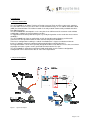
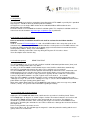
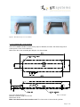
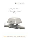
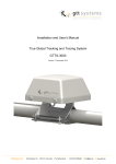
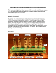
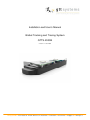
Installation and User’s Manual
Global Tracking and Tracing System
GTTS-2000B
Version 1.1 June 2009
GTTSystems B.V. Herfordstraat 16 7418 EX Deventer, The Netherlands T 0570 605075 F 0570 677755 E [email protected] W www.gtts.eu
PREFACE
The information in this Installation and User’s Guide is subject to change in order to improve reliability,
design or function without prior notice.
In no event GTTSystems B.V. will be liable for technical or editorial errors or omissions herein.
Nor for incidental, special or consequential damages from the furnishing, performance or use of this
Installation and User’s Guide.
WARNINGS AND NOTICES
Read this installation and User’s Manual before unpacking and installing the GTTS-2000B.
There are no user serviceable parts inside. Do not open the GTTS-2000B under any circumstances.
If the internal battery has to be replaced, contact your dealer.
If GTTS-2000B systems were ordered with (optional) mounting magnets, the magnets are in factory
mounted to reduce risk of injury.
If magnets are mounted, a warning label will be present inside the box or crate and/or on the lid of the
GTTS-2000B
Warning Label:
Caution:
The magnets are very strong. The 4 magnets have a total holding force of
1080 N (~108 Kg)
Approvals:
CE / EMC EN 60945 (2002), chapter 9
EN 60945 (2002), chapter 10
Table of Content
1
INTRODUCTION.............................................................................................................................. 4
1.1 GENERAL INFORMATION ................................................................................................................. 4
1.2 SYSTEM DESCRIPTION ................................................................................................................... 4
2
INSTALLATION ............................................................................................................................... 6
2.1 UNPACKING .................................................................................................................................. 6
2.2 ACTIVATION IN THE IRIDIUM NETWORK ............................................................................................ 6
2.3 INSTALLATION GENERAL ................................................................................................................. 6
2.3.1 INSTALLATION WITH MAGNET MOUNTING.......................................................................................... 6
2.3.2 INSTALLATION WITH SCREW MOUNTING ........................................................................................... 7
3
CONFIGURATION ........................................................................................................................... 8
3.1 CONFIGURATION DAT-01 .............................................................................................................. 8
3.2 CONFIGURATION AUT-01 .............................................................................................................. 8
3.2 BATTERY LIFE ............................................................................................................................... 9
4
REPLACEMENT OF THE BATTERY .................................................................................................... 9
5
SPECIFICATIONS ......................................................................................................................... 10
Page 3 of 10
1 Introduction
1.1 General information
The GTTS-2000B is an Iridium Tracking & Tracing System to Track and Trace your truck, container,
vessel or other assets in areas where there is lack of GSM coverage. It uses Iridium Short Burst Data
(SBD) for communication. The Iridium network is the only network commercially available that offers
true global coverage.
The GTTS-2000B was developed in such a way that it can fulfil most of the customer needs without
modifications, add-ons or special software versions.
It’s ruggedized all weather proof housing was especially designed to survive under the most extreme
conditions.
The GTTS-2000B runs from an application specific designed integrated battery pack that will
guarantee fail safe operation under the most extreme temperature conditions.
In the basic configuration no wiring is needed. Installation time is kept to an absolute minimum
because it provides magnetic mounting and integrated Iridium and GPS Antenna’s.
An integrated motion sensor and especially designed hardware and software ensures that a maximum
of position and status reports can be generated from the batteries life span.
The GTTS-2000B is shipped pre-programmed with application specific software configuration.
Configuration can be altered “over the air” if the unit is operational.
1.2 System description
Figure 1. System description
Page 4 of 10
An installed GTTS-2000B will activate the internal GPS at preset time intervals and measure its
geographical position. The position, along with other information, is then send through the Iridium
satellite constellation to the Iridium Gateway. In the Gateway the data is processed and send to a preconfigured IP-address and/or E-mail address. For optimum data transport efficiency and cost
effectiveness reasons, two position reports are packed into one Iridium message.
Depending on the end-user’s application, it is often desired to use geographical maps to display the
position along with other information. An example of GTTS-2000 series’ on a GEO map can be found
in figure 2 below.
Figure 2. GTTS-2000 series on a map display
All the dealers of GTTS-2000 series Tracking & Tracing Systems have their own GEO services, or can
provide it.
For the dealer list please visit http://www.gtts.eu/dealers.php
Page 5 of 10
2 Installation
2.1 Unpacking
The GTTS-2000B is packed in a carton box. Unpacking of the GTTS-2000B, especially if it is provided
with magnets, should be done on location prior to installation.
GTTSystems uses the unique IMEI number of the embedded Iridium SBD modem for unit
identification and registration.
Each box contains a GTTS-2000B and a brief installation guide. This complete Installation and User’s
manual can also be found on http://www.gtts.eu/products.php in pdf format.
2.2 Activation in the Iridium Network
Prior to mechanical installation the GTTS unit shall be activated in the Iridium Satellite
Network.
Send an email to [email protected] with a list of IMEI numbers of the units that needs to be
activated. Only activation requests from authorized dealers can be processed. The IMEI numbers can
be found on 2 different barcode labels on the bottom of the unit and also on a barcode label on the
carton packing. IMEI nr. always starts with 300034……….
Activation is normally realized the same day during GTTSystems B.V. business hours.
Your subscription starts from this day.
2.3 Installation general
READ THIS FIRST
The GTTS-2000B is very easy to install. It shall be installed in horizontal position onto a (ferro) steel
surface with no obstructions to the sky above.
As soon as the GTTS-2000B is mounted onto ferrous metal, it will be switched on automatically.
If the GTTS is provided with magnets, be aware. These magnets are very strong!!!
The GTTS-2000B will send a first GPS position automatically to confirm the unit is switched on and
working properly. Please note that it can take several minutes before a message from the unit is
received (depending on satellites in sight). GPS takes typically 40..50 seconds for a cold start fix.
Latency in the Iridium Network is very low. Typical values measured 12 .. 15 seconds
When the GTTS-2000B is removed from ferrous metal, it automatically will be triggered to send a
‘sabotage message’. As soon as the ‘sabotage message’ is sent, the GTTS-2000B will switch into the
power-down state again (factory power-down state).
When not in power-down mode, the GTTS-2000B will send a battery status message every 10080
minutes (1 week). See §3.2 for more information regarding the battery.
2.3.1 Installation with magnet mounting
Holding the GTTS-2000B with both hands, hold it over the area where it shall be placed. Tilt the
GTTS-2000B appr. 45 degrees as shown in figure 3 below. Then lower it onto the steel surface and
turn the GTTS-2000B until the magnets make contact with the steel surface. Try to do this as
controlled as possible to avoid a ‘slam’ and keep your fingers free from the GTTS-2000B surface
contact area. Slamming the unit onto the steel surface could cause damage due to extreme G-forces
that might occur.
Reverse this procedure to remove an unit.
Never try to slide a unit. This will damage the magnetic’s corrosion protective coating and the steel
(paint) surface it is mounted on.
Page 6 of 10
Figure 3. Placement on top of a sea container.
2.3.2 Installation with screw mounting
If the GTTS-2000B should be installed using 4 pieces M5 bolts, the bolts shall not be longer then
18mm plus the steel surface thickness.
Drill 4 holes Ø 5,5 mm according the drill plan. See figure below
X is steel surface thickness
Figure 4. Drill plan
Bolt M5 maximum length is X+18 mm
Dimensions in mm.
Make sure that bottom center touches steel. The ferro sensor is located at this position.
Page 7 of 10
3 Configuration
The GTTS-2000B ‘s are shipped from factory in a pre-configured state.
The customers desired configuration is passed to GTTSystems B.V. by the dealers. The units are then
configured, tested, packed and shipped. Currently there are two configurations released.
Please note that GTTS-2000B configurations are setup in such a way that the battery life span is
optimized without compromising too much in reporting time intervals and customers applications.
Configuration can be altered “over the air”, but the reporting time interval can never be set smaller
than one hour.
3.1 Configuration DAT-01
Characteristic of configuration “DAT-01” is that the GTTS-2000B reports continuously at a preset time
interval. In this configuration the unit is programmed to send a report every 180 minutes. Every report
holds 2 GPS positions (calculated and stored every 90 minutes).
This configuration is often used to track and trace vessels.
As soon as the GTTS-2000B is mounted onto ferrous metal, it will switch on automatically.
The GTTS-2000B will send a first GPS position immediately to confirm the unit is switched on and
working properly. Please note that it can take several minutes before a message from the unit is
received (depending on satellites in sight).
The software is adapted to deal with poor GPS reception and poor or no Iridium network. It will enter
power down modes to conserve the battery. At preset time intervals it will try to get a GPS fix and a
connection to the Iridium network again.
When the GTTS-2000B is removed from ferrous metal, it is triggered to send a sabotage message.
As soon as the sabotage message is sent, the GTTS-2000B will switch into the power-down state
again (factory power-down state).
When not in power-down mode, the GTTS-2000B will send a battery status message every 10080
minutes (1 week).
3.2 Configuration AUT-01
Characteristic of configuration “AUT-01” is that the GTTS-2000B reports at a preset time interval.
But only if the motion sensor detected motion within this time interval.
In this configuration the unit is programmed to send a report every 120 minutes. Every report holds 2
GPS positions (calculated and stored every 60 minutes).
This configuration is often used to track and trace vehicles and (sea) containers
.
As soon as the GTTS-2000B is mounted onto ferrous metal, it will switch on automatically.
The GTTS-2000B will send a first GPS position immediately to confirm the unit is switched on and
working properly. Please note that it can take several minutes before a message from the unit is
received (depending on satellites in sight).
The software is adapted to deal with poor GPS reception and poor or no Iridium network. It will enter
power down modes to conserve the battery. At preset time intervals it will try to get a GPS fix and a
connection to the Iridium network again.
When the GTTS-2000B is removed from ferrous metal, it is triggered to send a sabotage message.
As soon as the sabotage message is sent, the GTTS-2000B will switch into the power-down state
again (factory power-down state).
When not in power-down mode, the GTTS-2000B will send a battery status message every 10080
minutes (1 week).
Page 8 of 10
3.2 Battery life
The GTTS-2000B is equipped with a 7.2 Volts / 36Ah Lithium-Thionyl-Chloride battery.
Contradictory to other batteries e.g. alkaline or so, is that the cell voltage does not drop if the battery
wears and therefore it is difficult to measure the actual battery conditions. However, there are methods
to measure the remaining capacity, but this would cause conflicts in the GTTS-2000B electronic
circuits and software. Therefore calculations and measurements were made to determine the power
consumption of every circuit in the GTTS-2000B. Timers in the GTTS-2000B register the period of
time every consuming circuit is active. The unit automatically will send a “Battery Status Message”
every week.
Taking in count the self-discharge of the battery, average time to get a GPS fix and the average time
needed on the Iridium network to send a message, a prognoses of the battery life span related to
several reporting time interval was calculated.
Rule of thumb is that 3650 reports can be send on one battery.
This could result in the following scheme:
8 reports and a total of16 positions per day
6 reports and a total of16 positions per day
4 reports and a total of16 positions per day
2 reports and a total of16 positions per day
1 reports and a total of16 positions per day
1 reports and a total of1 position per day
battery life span 3.2 years
battery life span 3.6 years
battery life span 4.2 years
battery life span 5.0 years
battery life span 5.5 years
battery life span 10 years
For a GTTS-2000B configured according “DAT-01”, this would mean that the battery should last 3.2
years.
These life spans are estimated and depend on a lot of conditions like e.g. working temperature, time
needed to get a GPS fix etc.
Therefore it is of the utmost importance that the GTTS-2000B is placed horizontally with a clear view
to the sky above to obtain a GPS fix and connection to the iridium network in a minimum of time.
There are a number of GTTS-2000B test units in the field since September 2008 with the “DAT-01”
configuration.
At a certain time these test units will return to the engineering department (Leap Development B.V.)
and the remaining battery capacity will be measured. Then we are able to check if the calculations and
predictions of the batteries life span are accurate or need some adjustments.
In no event GTTSystems B.V. will be liable for battery wear.
4 Replacement of the battery
If the battery needs to be replaced, we advice to return the GTTS-2000B to the service department of
your dealer.
Along with the battery, the gasket in the lid of the unit, shall also be replaced to ensure optimum
moisture ingress protection.
The dealer will either replace the battery and gasket in their own service department or have the unit
shipped to the service department of GTTSystems B.V. for refurbishment.
Page 9 of 10
5 Specifications
Physical
Size
Weight
Optional Magnets Weight
Magnets Holding Force
350x100x50 mm
1250 gr.
180
1080 N (~108 Kg)
Environmental
Operating Temperature
Storage Temperature
Humidity
-35..+65 C
-35..+25 C
Relative 100%
Electrical
Battery
Power consumption
Estimated Nr. Of
Transmission from 1 Battery
7.2V / 36000mAh
Sleep: 216 uA
3650
Interface
2.4 GHz wireless ANT
used for optional wireless sensors and/or
maintenace & Control
Sensors
Motion Sensor
Ferro Detector
used to control reporting frequency
used as turn on/off switch and
removal/sabotage detector
Satellite
Iridium Constellation
Frequency
Transmission
Communication
Iridium RX/TX Antenna
True Global Coverage
1616 - 1626.5 MHz
Short Burst Data TDMA/FDMA
Direct IP and/or E-mail
integrated Patch Antenna
GPS
Accuracy
GPS RX Antenna
20 channels Sirf III
1.8 m CEP(95)
integrated Patch Antenna
Page 10 of 10