1
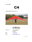
REVOLUTION HANG GLIDER OWNER and SERVICE MANUAL Rev 2
Part No 109934
A4-8331
REV OWNER and SERVICE MANUAL
AIRBORNE DIRECTIVES
AS THE SERVICE HISTORY OF THE AIRFRAME EVOLVES AIRBORNE WILL FROM TIME
TO TIME ISSUE AIRBORNE DIRECTIVES, WHICH DETAIL ANY CHANGES TO THE
MAINTENANCE MANUALS, PILOT’S OPERATING HANDBOOK, OR ANY OTHER DETAILS
THAT AIRBORNE DEEMS NECESSARY FOR OWNERS TO BE NOTIFIED OF.
THE WEB ADDRESS FOR AIRBORNE DIRECTIVES IS:
HTTP://WWW.AIRBORNE.COM.AU/
WARNING
THE INFORMATION IN THIS MANUAL NEEDS TO BE FOLLOWED, AND IT IS NOT
ACCEPTABLE TO MAKE CHANGES TO THE MATERIALS AND OR PHYSICAL FEATURES
OF THIS AIRCRAFT. IN PARTICULAR THE GRADES OF BOLTS THAT HAVE BEEN
UTILISED IN THE MANUFACTURE OF THIS AIRCRAFT ARE CRITICAL FOR ITS
CONTINUING AIRWORTHINESS. NEVER REPLACE BOLTS WITH ANY OTHER SIZE OR
GRADE. GRADE 8 BOLTS ARE NOT INTERCHANGEABLE WITH AIRCRAFT (AN) GRADE
BOLTS. THE FATIGUE CHARACTERISTICS OF AIRCRAFT GRADE BOLTS ARE SUPERIOR
TO OTHER BOLTS AND ALLOW LONGER SAFE SERVICE LIFE UNDER CYCLIC LOADS
LIKE THOSE EXPERIENCED IN AIRCRAFT. THE LENGTH OF THE BOLT IS IMPORTANT. IF
A SHORTER BOLT IS USED THE THREAD MAY ENCROACH ON THE LOAD BEARING
AREA, WHICH INCREASES THE STRESSES EXPERIENCED BY IT.
Issue Date May 2011 Rev 2
Page 2
REV OWNER and SERVICE MANUAL
MANUAL REVISION HISTORY
Revision No
0
1
2
Description
Initial Issue
Inclusion Rev 14.5
Improved tuning data
Inclusion of Rev 14.5 Sprog
Settings (Confirmed DHV
testing 07/06/11)
Applicable
Serial No
RN-13.5-001 >
RN-13.5-001 >
RN-14.5-001>
Date
30 November 2009
RN-13.5-001 >
RN-14.5-001>
9 May 2011
7 April 2010
Table 1 Revision History
Issue Date May 2011 Rev 2
Page 3
REV OWNER and SERVICE MANUAL
TABLE OF CONTENTS
MANUAL REVISION HISTORY _______________________________________ 3
TABLE OF CONTENTS _____________________________________________ 4
FIGURE INDEX ____________________________________________________ 6
Section 1
DESIGN FEATURES ____________________________________ 7
Section 2
SPECIFICATIONS and OPTIONS __________________________ 8
STANDARD SPECIFICATIONS___________________________________________________8
OPTIONS AND ALTERNATIVES__________________________________________________9
Section 3
OPERATING LIMITATIONS______________________________ 10
Section 4
WARRANTY STATEMENTS _____________________________ 11
Section 5
ASSEMBLY PROCEDURES _____________________________ 12
ASSEMBLING ON THE FRAME _________________________________________________12
ASSEMBLING LYING FLAT ____________________________________________________16
Section 6
PRE-FLIGHT INSPECTION ______________________________ 18
HANG GLIDER DAILY INSPECTION _____________________________________________19
Section 7
BREAK DOWN PROCEDURE____________________________ 20
Section 8
SHORT PACKING _____________________________________ 22
ASSEMBLY FROM SHORT PACK _______________________________________________22
Section 11
FLIGHT TECHNIQUE ___________________________________ 25
TAKE OFF ..DON'T FORGET TO HOOK IN..._______________________________________25
TURNS _____________________________________________________________________25
STALLS ____________________________________________________________________25
SPINS______________________________________________________________________25
THERMALLING ______________________________________________________________26
LANDING ___________________________________________________________________26
Section 12
PITCH STABILITY SYSTEM _____________________________ 27
PITCH STABILITY ____________________________________________________________27
CHECKING THE REV STABILITY SYSTEM _____________________________________27
CHECKING THE WASHOUT STRUT (SPROG) ANGLES ___________________________27
SIGHTING TRAILING EDGE__________________________________________________29
SPROG ADJUSTMENT FOR SYMMETRY_______________________________________30
SECTION 13 TUNING SUMMARY ____________________________________ 31
PITCH TRIM _________________________________________________________________31
ROLL TRIM ADJUSTMENTS____________________________________________________32
HANDLING AND PERFORMANCE TUNING _______________________________________33
Section 14
TUNING DETAILS _____________________________________ 34
BATTEN TENSION ADJUSTMENT _______________________________________________34
Issue Date May 2011 Rev 2
Page 4
REV OWNER and SERVICE MANUAL
TIP WAND ADJUSTMENT _____________________________________________________ 34
OUTER RING ADJUSTMENT___________________________________________________ 35
Standard Setting ___________________________________________________________ 35
Adjusting Dihedral__________________________________________________________ 35
SAIL TENSION ADJUSTMENT _________________________________________________ 36
TIP LEVER ADJUSTMENT_____________________________________________________ 36
Section 15
PERIODIC INSPECTIONS and MAINTENANCE _____________ 37
MAINTENANCE SCHEDULE ___________________________________________________ 37
LOG BOOK _________________________________________________________________ 37
NOTES ON PERIODIC INSPECTIONS ___________________________________________ 38
AIRFRAME TUBING________________________________________________________ 38
CARBON CROSS TUBES ___________________________________________________ 38
CARBON SPROGS ________________________________________________________ 38
BOLTS __________________________________________________________________ 38
SAILS ___________________________________________________________________ 39
INSPECTION AFTER HARD LANDING _________________________________________ 39
DEFECT REPORTS ________________________________________________________ 39
Section 16
TRANSPORTATION AND STORAGE _____________________ 40
Section 17
MAINTENANCE RECORD ______________________________ 41
Section 18
HANG GLIDER COMPLIANCE SCHEDULES _______________ 42
GLIDER MODEL:
Rev 13.5 ___________________________________________________ 42
GLIDER MODEL:
Rev 14.5 ___________________________________________________ 43
Issue Date May 2011 Rev 2
Page 5
REV OWNER and SERVICE MANUAL
FIGURE INDEX
Figure 1 Nose Batten .................................................................................................................. 12
Figure 2 Front Wires ................................................................................................................... 13
Figure 3 Tension Cross Bars ..................................................................................................... 13
Figure 4 Keel Stand .................................................................................................................... 13
Figure 5 Load Tip Rod ................................................................................................................ 14
Figure 6 Close Tip Lever ............................................................................................................ 14
Figure 7 Unloading Batten Latch ............................................................................................... 14
Figure 8 Load Sprog ................................................................................................................... 15
Figure 9 Insert Under Surface Battens...................................................................................... 15
Figure 10 Install Nose Fairing .................................................................................................... 15
Figure 11 Install Rear Leading Edges (RHS shown) ............................................................... 22
Figure 12 Unzip Cell.................................................................................................................... 22
Figure 13 Rear Leading Edge Orientation ................................................................................ 23
Figure 14 Step Down Ring Orientation ..................................................................................... 23
Figure 15 Tension Sail................................................................................................................ 24
Figure 16 Adjust Sail Tension .................................................................................................... 24
Figure 17 Setting Reference Keel Angle with protractor ......................................................... 27
Figure 18 Setting Reference Keel Angle with phone ............................................................... 27
Figure 19 Measuring Washout Strut Angle with protractor ..................................................... 28
Figure 20 Measuring Washout Strut Angle with phone ........................................................... 28
Figure 21 Symmetry of Sprog Adjustment................................................................................ 29
Figure 22 Standard Batten Tension........................................................................................... 34
Figure 23 Tip Wand Angle Adjustment ..................................................................................... 34
Figure 24 Outer Ring Standard Setting (Dihedral)................................................................... 35
Figure 25 Outer Ring Dihedral Adjustment............................................................................... 35
Figure 26 Sail Tension................................................................................................................ 36
Figure 27 Tip Lever Adjustments............................................................................................... 36
Issue Date May 2011 Rev 2
Page 6
REV OWNER and SERVICE MANUAL
Section 1
DESIGN FEATURES
The Revolution is the result of continued refinement of our high performance topless hang glider.
The goals for the Rev development were to increase high-speed performance, reduce weight and
retain the great handling, which has been a characteristic of AirBorne gliders. We had the luxury of
starting from the ground up, with only the basic control frame hardware remaining unchanged. All
of our design objectives have been met or exceeded.
The first time you see a REV, you’ll notice some obvious changes from the C4. The planform has a
slightly deeper mid span chord, the tip wands exit the LE with a more tangential sweep and the
percentage of double surface is greater.
When you look at the sail you’ll see it’s cleaner than ever. With the VG on it is twang tight and
wrinkle free. The top surface layout is the now the common “rim & fill” style with load bearing
heavier cloths used where needed. Lighter, more flexible laminates “fill” in the remainder allowing
minor stretching to make the skin slick and tight. The under surface carries much more tension than
previous wings but still allows for blow-down outboard to optimise the airfoil for higher speeds. The
sail also includes as standard, a fairing for the pullback hardware. After you tension the cross bars
you can just pull the zip and the rear keel hardware is enclosed as an extension to the keel pocket.
Looking inside the sail you’ll see the engine room of the wing. The Camber Control System (CCS)
is the most obvious change with a tensioning system used to control the airfoil from distorting
upwards at high speeds. The CCS is activated when the VG approaches the full on setting and
maintains precise airfoil shape. The control of the airfoil results in a reduction in profile drag. The
distortion of the upper surface at high speeds has been well documented on other gliders and the
drag penalty is obvious.
In combination with the new airfoil section, with increased double surface and improved pitch
characteristics, the Rev gives the pilot smooth positive pitch feedback throughout an extremely wide
speed range.
At AirBorne we have a well-developed quality assurance program, ensuring that every glider is built
in accordance with the standard it was designed and tested to. This gives even the most experienced
pilot a sense of security.
We hope that you have hours of great flying with your new glider. Fly high and safely.
Rick, Russell and Shane Duncan, Rob Hibberd and Paul Mollison,
AirBorne WindSports
Issue Date May 2011 Rev 2
Page 7
REV OWNER and SERVICE MANUAL
Section 2
SPECIFICATIONS and OPTIONS
STANDARD SPECIFICATIONS
SAIL AREA
WING SPAN
ASPECT RATIO
NOSE ANGLE
DOUBLE SURFACE %
BATTENS
GLIDER WEIGHT
PACK UP LENGTH
SHORT PACK LENGTH
RECOMMENDED PILOT
HOOK IN WEIGHT RANGE
(Includes Equipment)
VNE (Recommended
Maximum Velocity)
VA (Recommended Maximum
Rough Air Manoeuvring
Velocity)
VD (Maximum Steady State
Velocity)
REV-13.5
METRIC
IMPERIAL
13.43 sq m
144 sq ft
10.04 m
32.9 feet
7.5
126-131 degrees
95%
24 + 6
33 kg
72 pound
5.0 m
16.4 ft
3.9 m
12.8 ft
REV-14.5
METRIC
IMPERIAL
14.45 sq m
156 sq ft
10.64
34.9 ft
7.8
126-131 degrees
95%
24 + 6
35 kg
77 pound
5.3 m
17.4 ft
4.2 m
13.8 ft
70-105 kg
154-231 pounds
85-120 kg
187-264 pounds
90 km/h
55 mph
90 km/h
55 mph
74 km/h
46 mph
74 km/h
46 mph
125 km/h
78 mph
125 km/h
78 mph
Table 2 Specifications
Note: The stall speed of the Rev at maximum recommended wing loading is less than the minimum
requirement of 25 mph (40 km/h).
Conversions: * 0.4536 kg/pound * 25.4 mm/inch * 1.609 km/mile
Va = Test speed x 0.707
Vne = Test Speed x 0.816
Issue Date May 2011 Rev 2
Page 8
REV OWNER and SERVICE MANUAL
OPTIONS AND ALTERNATIVES
The Rev has various options or alternatives available. An alternative is used when one or more
choices are required but one choice must be made. An option is something that can be included on
the glider but is not required
The Rev airframe is standard with 7075 alloy and carbon rear leading edges. Carbon transverse
battens. The sail standard configuration is leading edge and trailing edge material PX10 with PX5
used as the main sail in fill cloth. The main sail can be white or grey. The undersurface is made from
4oz dacron with 3 separate panels with a variety of colours available.
Alternatives
Control Frame
Airfoil 13.5
Airfoil 14.5
Micro Drag 13.5
Micro Drag 14.5
Base Bar
Round
Part No
Description
Comment
109960
110402
109964
110403
Aluminium Airfoil
56mmx26mm
Aluminium Airfoil
76mmx21mm
Comfortable with good feel
108609
Standard Round Speed Bar with foam grips
Streamline
108857
Carbon
108563
Aluminium Round
28mm x 2 mm
Aluminium Airfoil
46mmx20mm
Moulded Carbon
110328
110401
110329
110400
Standard Hinge
Standard 10.8x0.7mm 7075 alloy battens
Light Weight Hinge
Curved section 10.8x0.7mm with straight
section 12x.45mm. Lighter and stiffer
100347
110348
Aluminium Round
Carbon Round
Standard 7075 alloy
Carbon tube with bonded lug. Stiffer and
lighter
109356
Carbon Kevlar
1800x195
Helps retain airfoil shape at high speeds.
Improved high-speed glide.
Battens
Standard 13.5
Standard 14.5
Light 13.5
Light 14.5
Sprogs
Alloy 7075
Carbon
Options
Carbon Inserts
Reduced drag. Broader section
Airfoil Speed Bar. Reduced Drag
Carbon Speed Bar airfoil design with
rounded section for holding. Good in cold.
Table 3 Airframe Alternatives and Options
Issue Date May 2011 Rev 2
Page 9
REV OWNER and SERVICE MANUAL
Section 3
OPERATING LIMITATIONS
WARNING
Hang Gliding is a high-risk sport. The safe operation of this hang glider
ultimately rests with you, the pilot. We believe that in order to fly safely you
must maturely practice the sport of hang gliding. You should never fly this hang
glider beyond the placard limits. The velocity never to exceed (VNE) for your
glider is given in Section 2, as is the maximum speed for manoeuvres or flying in
rough air (VA). The indicated airspeeds given are for calibrated instruments
mounted on, or near, the base bar of the control frame. It is recommended that
you fly your REV with an airspeed indicator, as it is relatively easy in the VG on
configuration to exceed the placard limitations. Flight operations should be
limited to non-aerobatic manoeuvres where the pitch angle does not exceed 30
degrees up or down to the horizon and where the bank angle does not exceed 60
degrees. Aggressive stalls and spins should not be attempted. Operations outside
the recommended flight envelope, such as aerobatic manoeuvres or erratic pilot
technique may ultimately produce equipment failure. Your glider was designed
for foot launched soaring and should not be flown by more than one person at a
time. It should not be flown backwards or inverted. The setting up and breaking
down of a hang glider, transportation on cars and flying itself will have an effect
over time on its structural integrity. The glider will require maintenance as
outlined in the maintenance section of this manual. Like any aircraft safety
depends on a combination of careful maintenance and your ability to fly
intelligently and conservatively. The owner and operator must understand that
due to inherent risks involved in flying a hang glider, no warranty of any kind is
made or implied against accidents, bodily injury and death, other than those that
cannot by law be excluded. We hope that your new glider will provide you with
many hours of safe flying.
Issue Date May 2011 Rev 2
Page 10
REV OWNER and SERVICE MANUAL
Section 4
WARRANTY STATEMENTS
This warranty extends to new Hang Gliders and/or accessories and equipment manufactured by
AIRBORNE WINDSPORTS PTY LTD ("Airborne") and shall not embrace any other accessories or
equipment in the sale.
AIRBORNE warrants to the customer the hang glider and/or accessories manufactured or supplied
by AIRBORNE to be free from defect in material and workmanship under normal use and service
and of merchantable quality and fit the purpose for which they are ordinarily used. This Warranty
will apply for a period of ninety (90) days from the date of dispatch of the hang glider not
withstanding the number of hours flown but subject to the hang glider remaining the property of the
customer. This warranty does not exclude any rights implied in favour of any customer by any
applicable Federal and State legislation.
AIRBORNE will make good any parts required because of defective material or workmanship as set
out in the Warranty.
THE WARRANTY WILL NOT APPLY TO:
Any mechanical adjustments, parts, replacements, repairs or other servicing that in the judgement of
AIRBORNE are made or should be made as maintenance.
Any defect caused by any alteration or modification not approved by AIRBORNE.
Any defect caused by the fitment of parts that are not made or approved by AIRBORNE.
Any defect caused by misuse, accidents, negligence or failure to carry out proper maintenance
service.
Damage caused by continued operation of the hang glider after it is known to be defective.
Any defect or consequential loss, damage or injury caused by overloading.
Loss of use of the hang glider, loss of time, inconvenience, damages for personal injuries, loss of
property or other consequential damages.
Failure due to wear and tear, accident, fire, incorrect or incomplete rigging and/or assembly,
exposure to the elements, operation outside the placarded limitations and repairs attempted or made
other than by AIRBORNE or it's authorised agent.
AIRBORNE will replace, free of charge, any original part that is determined by it to be defective
under the terms of this Warranty and reserves the right to pay monetary compensation or make good
the defect in any manner it deems appropriate.
The customer is responsible for transporting the hang glider or parts to and from AIRBORNE or its
authorised agent when making claims under this Warranty. The hang glider or parts are at the
customer's risk whilst in transit to and from AIRBORNE or its authorised agent.
NOTE: Warranty service is available to the customer from AIRBORNE WINDSPORTS PTY
LIMITED or authorised agent.
Issue Date May 2011 Rev 2
Page 11
REV OWNER and SERVICE MANUAL
Section 5
ASSEMBLY PROCEDURES
The wing can be assembled in two positions, either lying flat or standing on the control frame.
Assembling the REV on the control frame is the most popular method of assembly in light winds.
This method is preferable as the sail is less prone to being soiled or damaged during assembly. In
higher winds it is preferable to lay the glider flat for assembly with the nose into the wind until
ready to launch.
ASSEMBLING ON THE FRAME
Unzip Bag. Lay the wing down with zip up and the nose facing approximately 120 degrees from the
wind direction.
Assemble Control Frame. Spread the control frame down tubes and connect the base bar. The pip
pins are then inserted from front to rear. Check that all the rigging wires are outside the control
frame.
Stand Glider Up. Rotate the control frame to the vertical position and rotate the wing 180 degrees
so that it is sitting on the base bar.
Remove Bag. Remove the glider bag and unclip all of the ties.
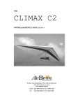
Locate Nose Battens. Locate the nose battens on the
locating pins. If you fail to load the battens prior to
tensioning the glider the VG should be pulled full tight
before attempting to locate the battens.
Figure 1 Nose Batten
Spread Leading Edges. Carefully spread both leading edges out half way then spread leading edges
to their approximate flying position. Check the side wires are not twisted.
It is essential that the keel and the leading edges are kept in the same plane when spreading
the leading edges or damage will result.
Issue Date May 2011 Rev 2
Page 12
REV OWNER and SERVICE MANUAL
Attach front flying wires. Ensure that the front
flying wires are secure and that the quick clip is
positively locked.
Figure 2 Front Wires
Insert mainsail battens #1 - 5. Remove the battens from the bag. The red battens are for the left
side and the green for the right. Insert the battens from the centre to the tip with gentle pressure, until
the batten meets resistance. Shake the sail at the trailing edge whilst maintaining gentle pressure on
the batten to allow the batten to be inserted over the cross bar.
DO NOT FORCE THE BATTENS!
Tension cross bars. The cross bars are tensioned
by pulling the 2:1 pull back rope until the shackle
is positioned on the quick clip. Ensure that the
catch is positively locked.
Figure 3 Tension Cross Bars
Install keel stand. The rear keel extension can be
removed and inserted through the hole on the lower
side of the keel. This raises the wing tips and
allows easier installation of battens. The keel stand
should only be used in light wind conditions and
level ground otherwise the keel may be damage.
Figure 4 Keel Stand
Issue Date May 2011 Rev 2
Page 13
REV OWNER and SERVICE MANUAL
Insert tip rods. Remove the tip bags and insert the tip rod into the tip plug fitting at the rear of the
leading edge. Ensure that the rod is fully inserted.
Load tip rod. Move to the front of the wing. For the
right tip hold the rear leading edge with your right
hand and the end of the sail with your left. Align the
lever plug and bend the tip tube towards the trailing
edge as you tension the tip tube. Locate the plug on
the end of the tube. When installing the left tip rod
the leading edge should be held with your left hand.
Figure 5 Load Tip Rod
Close tip lever. Move to the tip. Place your left
thumb in the rope loop of the tip lever and close
the lever. The lever should be held in the same
plane as the trailing edge. Do not let the lever
close rapidly as damage may result. Check that
the lever is against the fibre tube and is not being
forced above or below the tube. Close the velcro
once the lever is properly closed. Repeat for the
left wing using the opposite hands. Ensure
Velcro access is closed evenly
Figure 6 Close Tip Lever
Insert remaining mainsail battens.
Slide
battens into sail pocket. Unclip hinge fitting by
depressing with thumb. Close fitting while
supporting underside of batten
To adjust batten load tension, release latch from
sail and rotate batten clip. See Section 12 for
tuning instructions
CAUTION Damage to the latch mechanism
will occur if the fitting is not correctly
depressed before opening
Figure 7 Unloading Batten Latch
Issue Date May 2011 Rev 2
Page 14
REV OWNER and SERVICE MANUAL
Load washout struts. The washout rods or sprogs
should be rotated into position over the sprog
retainer loop and the zips closed fully. It is a good
time to inspect the junctions prior to closing all
zips. Lifting the trailing edge assists with locating
and zipping sprogs into position.
Figure 8 Load Sprog
Insert under surface battens.
The under surface battens should be inserted as far
as possible. The batten should then be pushed in
with your thumb. Use the string to pull the batten to
the rear of the pocket.
Figure 9 Insert Under Surface Battens
Install nose fairing. Attach the nose fairing applying
the top hook and loop fastener first then gently tension
over the nose plates and attach the hook and loop
fastener to the under surface.
Figure 10 Install Nose Fairing
Pre-flight inspection.
You are now ready for the wing pre-flight inspection as outlined in the next section. It is imperative
that you carry out this inspection every time you rig and before you fly.
Issue Date May 2011 Rev 2
Page 15
REV OWNER and SERVICE MANUAL
ASSEMBLING LYING FLAT
Unzip the bag. Lay the wing down with zip up and the nose facing into the wind. Unzip the bag and
unclip centre ties.
Assemble control frame. Spread the control frame down tubes and connect the base bar. The pip
pins are then inserted from front to rear. Check that all the rigging wires are outside the control
frame.
Rotate glider. Rotate the glider so that the control frame is under the wing. Make sure the rigging is
not tangled.
Remove bag. Remove the glider bag and unclip all of the ties.
Locate Nose Battens. Locate the nose battens on the locating pins. If you fail to load the battens
prior to tensioning the glider the VG should be pulled full tight before attempting to locate the
battens.
Spread leading edges. Carefully spread both leading edges out half way firstly then spread leading
edges to their approximate flying position. Check the side wires are not twisted.
It is essential that the keel and the leading edges are kept in the same plane when spreading
the leading edges or damage will result.
Insert tip rods. Remove the tip bags and insert the tip rod into the fitting at the rear of the leading
edge. Ensure that the rod is inserted all of the way.
Load tip rod. Move to the front of the wing. For the left tip hold the rear leading edge with your left
hand and the end of the sail with your right. Bend the tip rod towards the trailing edge as you apply
sail tension to the tip rod. Locate the tip lever on to the tip rod. When installing the right tip rod the
leading edge should be held with your right hand.
Close tip lever. Move to the trailing edge. Place your right thumb in the rope loop of the tip lever
and close the lever. The lever should be held in the same plane as the trailing edge. Do not let the
lever close rapidly as damage may result. Repeat loading and closing for the right wing.
Insert mainsail battens. Remove the battens from the bag. The red battens are for the left side and
the green for the right. Insert the battens from the centre to the tip with gentle pressure, until the
batten meets resistance. Shake the sail at the trailing edge whilst maintaining gentle pressure on the
batten to allow the batten to be inserted over the cross bar. DO NOT FORCE THE BATTENS
Tension cross bars. The cross bars are now tensioned by pulling the 2:1 tensioning rope until the
shackle is positioned on the quick clip. Ensure that the catch is positively locked. When tensioning
with the glider lying flat the keel can be raised approximately 200 mm to allow the side flying wires
to be loose.
Attach front flying wires. Lift glider and attach front flying wires. Ensure that the front flying
wires are secure and that the quick clip is positively locked.
Issue Date May 2011 Rev 2
Page 16
REV OWNER and SERVICE MANUAL
Install nose fairing. Attach the nose fairing applying the top hook and loop fastener first then gently
tension over the nose plates and attach the hook and loop fastener to the under surface.
Load Washout Struts. The sprogs should be rotated into position over the webbing retainer loops
and the zips closed fully. It is a good time to inspect the junctions prior to closing all zips.
Insert under surface battens. The under surface battens are inserted then pulled back into the rear
of the batten pocket with the string handle.
Pre-flight inspection. You are now ready for the wing pre-flight inspection as outlined in the next
section. It is imperative that you carry out this inspection every time you rig and before you fly.
Issue Date May 2011 Rev 2
Page 17
REV OWNER and SERVICE MANUAL
Section 6
PRE-FLIGHT INSPECTION
The wing was designed so that drag would be kept to a minimum. This means that most of the preflight checkpoints are enclosed.
A thorough pre-flight inspection is mandatory for any aircraft, and the best technique is a circular
walk around the wing.
The nose area is the ideal place to start your pre-flight check, followed by each assembly point.
Keep in mind the three most critical set up areas:
The nose quick clip
Control bar base tube fasteners
The cross bar tensioner quick clip.
Starting at the nose we suggest the following checklist (ensuring all bolts and fasteners have the
appropriate thread protruding beyond the nut).
Check the nose plate assembly ensuring that the VG routing is normal. Sight along both leading
edges checking for similar curves.
Walk towards the tip feeling for dents in the leading edge.
Check cross bar/leading edge junction and inner sprog assemblies through the zipper access.
Check outer sprog assemblies through the zipper access.
Check sail tip lever is fully closed and the sail is not damaged.
Check the tip rod is properly located and the rear leading edge is undamaged.
Walk towards the keel checking all battens are secured.
Check the sprogs are loaded and the zips are fully closed.
Check the cross bar retaining shackle is secured on the quick clip.
Repeat the above steps for the other side wing in reverse order.
Check all lower rigging is correctly routed and free from damage. The most likely area for damage
on wires is around the swage and thimble area.
Check control bar corners are correctly assembled with pip pin and cover.
Ensure the hang loop rocker is rotated 90 degrees to the keel and that hang loops are securely
positioned and in good order. The hang loop should be free to move in both directions.
Check control bar top assembly and ensure that the down tubes are straight.
Issue Date May 2011 Rev 2
Page 18
REV OWNER and SERVICE MANUAL
Unzip under surface and check cross bar hinge and restraining straps. The VG should be operated
and inspected to ensure it is functioning properly.
Ensure that the double surface is zipped up and nose fairing is secure.
Clip your harness into the main and back up hang loops and perform a "hang check". Make sure that
your harness is the correct distance from the base bar, your leg loops are secure and your carabiner
is locked.
HANG GLIDER DAILY INSPECTION
Inspection of the following items prior to every flight is required:
Check wires for twisted or jammed thimbles or damaged strands. Particular attention should be
given to side wires
Check wire ends for bolt and/or other fastener security.
Check for bends, dents, and scratches in all tubes.
Nose plate connections; spring clip retains front wires.
Tips secure; tip rod and lever undamaged, zipper closed.
Battens and batten clip ends not broken or bent.
A-frame connection on both sides.
Variable geometry operation (full and free movement).
Rear keel connections; spring clip retains shackle and tensioner cable.
Crossbar tension wire; free of kinks, frays, abrasions, broken strands.
Crossbar operation (free floating).
Sprog tubes, rod ends and clevis pins secure.
Sail condition; no tears, symmetrical appearance.
Harness straps and webbing secure, height adjustment correct.
Emergency parachute secure, correctly mounted and attached, operating handle accessible.
Issue Date May 2011 Rev 2
Page 19
REV OWNER and SERVICE MANUAL
Section 7
BREAK DOWN PROCEDURE
To break down your REV, just reverse the set-up procedure steps as described. Included here are a
few guidelines to follow which will save you time and prevent potential wear areas on your sail.
It is possible to leave the nose battens in during daily operations!
Set VG to full off position
Unzip keel pocket and install keel stand. Only use stand on even ground and in light winds.
Remove nose fairing.
Unzip sprogs and rotate them towards each other. The sprogs remain outside the sail.
Remove four or five tip battens and the under surface battens.
Unload tip lever and remove tip rod.
Fold tip lever towards sail and roll sail whilst keeping tension along the trailing edge. Fit tip bags.
Let off the sail tension and pull each wing in slightly.
Pull out the remaining battens.
Unzip centre rear zips and fold out control frame padding.
Fold both wings in symmetrically, bringing both leading edges back at the same time or in small
steps side to side.
Place padding over the keel end.
Roll the sail up parallel to the leading edge. One tie should be wrapped around the keel and leading
edge to hold them together whilst the other side wing is rolled.
Ensure that the sail is rolled into the leading edge pockets. It is important that the ties are not over
tensioned as this can damage the mylar insert.
Position glider bag.
Roll glider over and undo control bar PIP pins. Fold base bar rearward. Attach down tube padding
around down tube base. Place cover over the speed bar. Undo the two centre ties and fold the down
tubes between the leading edges. Lay the wires smoothly to avoid kinking. Secure the centre ties and
zip up bag.
The REV has 1x19 wires to minimize drag. The wires are more prone to kinking and should
be treated with care.
Issue Date May 2011 Rev 2
Page 20
REV OWNER and SERVICE MANUAL
For de-rigging flat, position top control frame padding. Undo nose wires and pull wing forwards
then follow steps as previously described.
If resistance is encountered during any phase of set up or break down procedure stop and investigate
before continuing.
Issue Date May 2011 Rev 2
Page 21
REV OWNER and SERVICE MANUAL
Section 8
SHORT PACKING
ASSEMBLY FROM SHORT PACK
This procedure is to be followed if the wing arrives in a short packed configuration. The short
packed wing has had the rear leading edges removed to reduce the packed size for transport.
The correct reassembly of the wing is critical for safety and performance. If there are any doubts
about the correct procedure for assembly after shipping contact AirBorne.
Remove wing from box. Ensure that all staples are removed before pulling the wing from the box.
Damage to the sail may result if caught on box staples.
Unzip bag. Remove padding from the nose of the wing. Remove all wing straps.
Assemble the control frame. Assemble control frame and rotate the wing so that it is lying flat on
the ground.
Spread leading edges. Spread both leading edges approximately ½ metre. Remove the tip bags,
which have been used as protection on the rear of the front leading edges. Remove clevis pin from
rear leading edge to allow it to insert into front leading edge tube.
Install Rear Leading Edges. Slide rear leading
edges with sprog facing forward through rear
access zip.
As the leading edge is pushed in through the tip
access zip ensure that the sprog exits the outer
sprog zip.
Insert rear leading edges in the correct side (left
and right hand sides are marked).
SPROG THROUGH ZIP
Figure 11 Install Rear Leading Edges (RHS shown)
Unzip cell. The cell inboard of the inner sprog
zip can be unzipped to allow easier access to the
front / rear leading edge junction. Access is
through the inboard sprog zip
Figure 12 Unzip Cell
Issue Date May 2011 Rev 2
Page 22
REV OWNER and SERVICE MANUAL
Slide rear leading edge into front tube. Ensure that the tube is in front of all cells. Take care when
sliding the tube into the sail as damage may result if forced
ROLL PIN
CLEVIS PIN
ADJUSTER SCREW
Figure 13 Rear Leading Edge Orientation
Rear leading edge orientation. Correct orientation of the clevis pin and ring is essential.
The photo shows the orientation of the right side leading edge. The clevis pin is inserted from the
outside under side of the leading edge then the clevis ring is fitted. Note that the clevis pin and step
down ring adjuster screw are on different planes.
Step down ring orientation. Standard setting are shown on the
rear leading edge sticker. Note that the 13.5 and 14.5 have
different positions i.e. the 14.5 more di-hederal
The velcro supplied should be used to cover the screw once it is
secured in the correct position.
ADJUSTER SCREW
ROLL PIN
(Note: photo shows Right Side Leading Edge)
Figure 14 Step Down Ring Orientation
Tension Sail. The sail is now tensioned. The
sail dowel adjuster is unscrewed from the M5
bolt and then positioned in the sail loop to allow
the bolt to pass through the webbing and
inserted into the thread of the dowel.
Note: Routing of the sail webbing is from front
of tube then underneath.
(Note: photo shows Left Side Leading Edge)
TENSIONER
Issue Date May 2011 Rev 2
Page 23
REV OWNER and SERVICE MANUAL
Figure 15 Tension Sail
Adjust sail tension. An M3 allen key is
used to adjust the sail tension so that the
dowel is located between the marks on the
placard on the rear leading edge. Once the
tension is correct the M5 lock nut should
be tightened to secure the fitting and
maintain correct tension
TENSION MARKS
M5 BOLT
LOCK NUT
Figure 16 Adjust Sail Tension
The glider can now be assembled as outlined in section 5 of the manual. A thorough pre-flight
inspection should be undertaken as per section 6 of the manual. Particular attention should be made
to the rear leading edge and sail attachment assemblies during the pre-flight inspection
Issue Date May 2011 Rev 2
Page 24
REV OWNER and SERVICE MANUAL
Section 11
FLIGHT TECHNIQUE
TAKE OFF ..DON'T FORGET TO HOOK IN...
The VG should be in the full off position for launching. The Rev has a slightly tail heavy static
balance and is very easy to launch. Hold the nose in a slightly elevated position, approximately 20
degrees to the slope with the wings level; accelerate smoothly to a hard run, keeping the nose at the
same angle.
It is important that the pilot accelerates smoothly during the launch run. Taking increasingly
larger steps until lift off is the preferred method. Too fast an acceleration will cause the nose to
rise rapidly with the risk of stall on launch.
TURNS
The REV can be easily directed into a turn even at slow speeds, however for a fast roll rate and
easier handling, it is best to pull on a little extra flying speed.
The REV will maintain a turn until the turn is removed by pilot input. Allow yourself plenty of
margin for safety.
Don't fly too slowly when flying close to the hill or other aircraft.
STALLS
When practising stalls make sure you have sufficient altitude. Start with VG off and push out slowly
(approx 1 mph per sec. speed reduction), the glider will tend to mush without dropping a wing. The
sink rate will increase in this mush mode more than two fold.
If you push out faster the nose will pitch higher, a gentle pitch down follows until the glider regains
flying speed and recovers from the stall. A stall at full VG will result in a much more rapid pitch
down and possible tip stall. This should be avoided.
Never stall the glider with the nose pitched up too high. This is a dangerous manoeuvre and can
result in a tail slide and severe tumble. As a guideline, the angle at which the glider stalls results in a
similar negative angle to recover.
If you push out too much in a turn the glider will turn tighter unless you are flying very slowly, in
which case you may tip stall. So keep on a little extra speed in turns until you get used to the glider.
SPINS
As with all recent gliders the REV will resist spinning. If you do stall a wing in a turn and enter the
initial stages of a spin, move your weight forward and to the high side of the rotation and the glider
will recover.
Issue Date May 2011 Rev 2
Page 25
REV OWNER and SERVICE MANUAL
THERMALLING
The optimum speed for thermalling is a little above stall speed; it may be necessary to fly faster than
this in rough conditions to maintain good control. Depending on the nature and area of the thermal a
bank angle of between 10 and 50 degrees can be used.
LANDING
Landing is easy in the REV. Your final approach should be a straight glide into the wind with
airspeed at faster than trim speed. You will feel positive (nose up) bar pressure. The VG should be
in the off position.
Reduce air speed slowly by relaxing the bar pressure smoothly. Keep wings level whilst looking
straight up your runway.
When the glider reaches trim speed a full flare is required. Flare aggressively in light or no wind,
holding the uprights out and up.
It is important that the pilot does not swing the legs forward whilst flaring. This results in the
pilot's centre of gravity moving forward which will cause the nose to drop.
Upon touchdown the pilot’s legs must provide a gentle deceleration, coasting to a stop (no aircraft
lands well with the brakes locked on!).
In strong wind it is possible to fly the glider onto the ground slowing up gradually. Be careful not to
flare too aggressively in windy conditions.
Issue Date May 2011 Rev 2
Page 26
REV OWNER and SERVICE MANUAL
Section 12
PITCH STABILITY SYSTEM
PITCH STABILITY
Stability in the pitch axis is provided by maintaining twist outboard of the cross bar leading edge
junction. Internal washout struts (sprogs) are used to maintain a minimum amount of twist, which is
required to achieve an acceptable level of pitch stability. Correct attachment and adjustment of the
sprogs is essential for stability.
Do not lower your sprogs below the factory standard settings. Lowering your sprogs will result
in reduced pitch stability.
Alterations to the lengths of rigging, airframe or adjustments to the airfoil can also have adverse
effects on pitch stability.
CHECKING THE REV STABILITY SYSTEM
The REV has a compensated internal sprog. As the VG pulls the sail flatter the inboard sprog
automatically lowers with the trailing edge.
The method described here is used to check the sprog angle relative to the keel angle of the glider.
CHECKING THE WASHOUT STRUT (SPROG) ANGLES
Angles may be measured using one of the following tools:
1. Protractor with built in spirit level (these are available from Airborne, part number 108624)
2. Digital level. iPhone and other android phones have spirit level applications available
3. Protractor with plumb bob
Inspection steps:
1. Fully assemble the glider ready for flight.
2. Pull the VG on full, until the restrictor wire from the nose plate to the cross bar is tight.
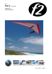
3. Place the protractor/level on the rear of the keel as shown in the following photograph. Do
not move the glider from this position.
4. Raise the rear keel to horizontal as 0° is a convenient reference point.
Figure 17 Setting Reference Keel Angle with
protractor
Figure 18 Setting Reference Keel Angle with phone
Issue Date May 2011 Rev 2
Page 27
REV OWNER and SERVICE MANUAL
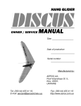
5. Sit protractor on sprog to check the measurement. Ensure that it is flat on the tube and not hitting
any hardware or the zip as this will cause error in the reading. Measure and record at each of the
washout strut locations as described in the table below.
Figure 19 Measuring Washout Strut Angle with
protractor
Figure 20 Measuring Washout Strut Angle
with phone
The table below indicates the minimum differential angle for each of the washout struts referenced
to the keel. Compare the measurements taken to the certified angles in the applicable table. Make
adjustments as required. See the following section for detailed instructions
As a guide for the magnitude of adjustment:
• the inboard struts change approximately 0.5° per revolution of the threaded strut cone.
• the outboard struts change approximately 1° per revolution of the threaded strut cone.
SPROG
Glider model
REV-13.5
REV-14.5
Inboard
Outboard
VG on
5.5°
5.5°
VG on
9.0°
8.0°
Table 4 Washout Strut Angles, All Models
Issue Date May 2011 Rev 2
Page 28
REV OWNER and SERVICE MANUAL
ADJUSTING WASHOUT STRUTS
To increase strut angle the strut or front cone is rotated anticlockwise. To decrease strut angle rotate
clockwise. This assumes viewing from the trailing edge
Aluminium Struts
1.
2.
3.
4.
5.
6.
Unzip and swing the strut out from the sail.
From the front of the tube remove the clevis ring and the clevis pin.
Adjust as required to achieve the correct settings.
Replace the clevis pin and clevis ring.
Replace the strut in the sail and capture it by doing the zipper up.
Tap the sail from above to position the strut into its flattest position. The strut angle is now
ready to be re-measured and test flown (as appropriate).
Carbon Struts
1. Unzip and swing the strut out from the sail.
2. Remove the clevis ring and the clevis pin from the alloy lug at the centre of the tube
3. Adjust as required to achieve the correct settings.
4. Replace the clevis pin and clevis ring.
5. Replace the strut in the sail and capture it by doing the zipper up
6. Tap the sail from above to position the strut into its flattest position. The strut angle is now
ready to be re-measured and test flown (as appropriate).
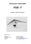
When making strut adjustments for a turn, it is wise to visually sight the trailing edge to check for
gross variations before test flying. To sight for asymmetry of the trailing, stand in front of the glider
with the keel horizontal & holding the nose wires. Slowly rotate the nose forward and backward,
notice when the trailing edge of each of the strut locations comes into and out of view.
SIGHTING TRAILING EDGE
If one side of the trailing edge comes into view earlier than the other side it indicates a higher sprog
settings. The sprog angles should be checked and re adjusted to specifications.
TRAILING EDGE
TRAILING EDGE
Figure 21 Symmetry of Sprog Adjustment
Issue Date May 2011 Rev 2
Page 29
REV OWNER and SERVICE MANUAL
SPROG ADJUSTMENT FOR SYMMETRY
Sprog adjustment may be required to remedy a turn when flying at tight VG settings approaching
full on at higher speeds. The following adjustments should only be made once sprog angles and
symmetry has been confirmed as outlined in the previous section
Adjustments should be made to the glider in the sequence as listed. The glider should be tuned
firstly in the VG off setting as outlined in the following section and then checked with the VG ½ and
then full on.
NOTE: We refer to the fast wing as the wing on the high side of the turn i.e. The right wing is the
fast wing if the wing is turning left and vice versa.
MILD TURN VG ON
ADJUSTMENTS WHEN THE GLIDER IS CONFIGURED VG 1/2 ON TO FULL ON
ADJUSTMENT METHOD
Remedy for left
turn
OUTBOARD SPROG ADJUSTMENT. The glider should
Raise the right
be assembled with the VG off. Unzip the outer sprog and
sprog by rotating
fold forward. Make appropriate adjustment and reinstall
the cone
sprog.
anticlockwise by
1/2 turn.
OUTBOARD SPROG ADJUSTMENT. If the glider still
Lower the left
turns the opposite sprog can be lowered as described.
sprog by rotating
the cone clockwise
by 1/2 turn.
Remedy for right
turn
Raise the left sprog
by rotating the cone
anticlockwise by 1/2
turn.
Raise the left sprog
by rotating the cone
anticlockwise by 1/2
turn.
Table 5 Tuning Matrix – Sprogs
Issue Date May 2011 Rev 2
Page 30
REV OWNER and SERVICE MANUAL
SECTION 13
TUNING SUMMARY
Your REV was test flown and delivered to you in good trim by either your dealer or by factory
pilots. If however, any adjustments are made to your glider, we recommend that they be recorded in
your maintenance log at the rear of this manual.
If you feel that the glider requires adjustment to trim in the roll or pitch axis you should check that
the problem is not caused by something asymmetrical in the frame or battens. In order of priority,
check the following:
Ensure that the wires are correctly routed.
Check the battens against the profile.
Check that the battens have the same tension on both sides.
Check tip rods are loaded correctly.
Check that the keel is straight.
Check that the sail is correctly mounted on the leading edges and within the adjustment lines.
Check that all sprog assemblies are not damaged.
Check leading edges are straight and the rear leading edges are located correctly.
Check that the tip lever is positioned so the sail at the tip is on the same plane as and not causing
distortion at the attachment point
PITCH TRIM
To make the glider trim faster move the suspension point forward, and to trim slower move the
suspension point rearward. The hang loop pillar should be adjusted one hole at a time.
A heavier pilot may make the glider trim slower than a lighter pilot. The heavier pilot causes an
increase in twist through extra leading edge flex. Minor changes in suspension point should be used
to fine-tune the glider for the particular pilot.
A glider can have a tendency to turn either to the right or the left. The Rev is very tuneable and can
be easily tuned to correct a turn. Tuning for spiral stability is also possible.
The following tables have been developed as a Matrix to allow quick access to the tuning technique
required to remedy a turn. Using the table assumes that the adjustment techniques are understood.
Section 14 - Tuning Details outlines more specific details of the various tuning options available on
the Rev.
Issue Date May 2011 Rev 2
Page 31
REV OWNER and SERVICE MANUAL
ROLL TRIM ADJUSTMENTS
The following tables show a summary of the tuning methods available on the Rev.
More detailed explanation of the various tuning methods are further explained in the following
section.
MORE SIGNIFICANT TURN
MILD TURN
MILD TURN
LIGHT TURN VG OFF
ADJUSTMENTS WHEN THE GLIDER IS CONFIGURED VG OFF TO 1/2 ON
ADJUSTMENT METHOD
Remedy left turn
DIFFERENTIAL BATTEN TENSION – See figure 22
If the turn is mild, then increasing and decreasing the batten
Increase tension on last
tension on either side can adjust it. If you increase the tension 5 battens on left side by
on the slow side you are effectively putting more camber in
1 turns at a time.
the airfoil therefore creating more lift on that side.
If you decrease the tension on the fast side you are
Decrease tension on last
decreasing the camber and reducing the amount of lift.
5 battens on right hand
The batten hinge clip can be rotated clockwise to decrease
side by 1 turn at a time.
tension or anti-clockwise to increase tension.
TIP BUNG ADJUSTMENT (TIP UP) - See figure 23
The tip wand angle can be adjusted to vary the washout at the
tip of the wing. An increase in the tip wand angle (upward tip
wand) will increase washout and therefore reduce lift on that
wing
Note: Standard setting for the tip wand is zero degrees
relative to the rear leading edge.
If more than a 2 turn adjustment is required the Outer Ring
Adjustment should be used.
TIP WAND ADJUSTMENT (TIP DOWN) – See figure 23
The tip wand angle can be adjusted to vary the washout at the
tip of the wing. A decrease in the tip wand angle (downward
tip wand) will decrease washout and therefore increase lift on
that wing.
Note: Standard setting for the tip wand is zero degrees
relative to the rear leading edge.
Do not reduce the tip angle more than 1 turn negative as pitch
stability will be affected.
REAR SECTION ADJUSTMENT. – See figure 24
If the turn still persists after the tip wands have been adjusted
the outer step down eccentric ring can be adjusted. The angle
that the rear section protrudes from the front section can be
altered by rotation of the outer eccentric (plastic) ring. The
location of this ring is fixed with a small screw. Remove screw
and reinstall once adjustment is made.
Remedy right turn
Decrease tension on
last 5 battens on left
side by 1 turn at a time.
Increase tension on last
5 battens on right hand
side by 1 turns at a
time.
Increase Tip Wand angle
on right side.
Increase Tip Wand
angle on left side.
Rotate nut side of bolt
assembly anticlockwise 1
complete turn
Rotate nut side of bolt
assembly anticlockwise 1
complete turn
Decrease Tip Wand
angle on left side.
Decrease Tip Wand
angle on right side.
Rotate nut side of bolt
assembly clockwise 1
complete turn
Rotate nut side of bolt
assembly clockwise 1
complete turn
Use the "Y" tool to rotate
the right step down ring
anti-clockwise one hole,
as viewed from the rear of
the leading edge. This
raises the RHS rear leading
edge.
The adjustment causes
dihedral of the rear leading
edge
Use the "Y" tool to rotate
the left step down ring
clockwise one hole, as
viewed from the rear of
the leading edge. This
raises the LHS rear
leading edge.
The adjustment causes
reduction in anhedral of
the rear leading edge
Table 6 Tuning Matrix - Frame
Issue Date May 2011 Rev 2
Page 32
REV OWNER and SERVICE MANUAL
HANDLING AND PERFORMANCE TUNING
The following table is designed to allow a pilot to reference methods of tuning the Rev to suit the
individual. Varying wing loading will affect the way the glider behaves in pitch and roll trim. For
example, a heavier loaded glider will tend to increase the flex in the leading edge tube causing more
washout. This increase in washout will tend to make the glider more spirally stable. A lightly loaded
glider will tend to be less spirally stable requiring more high siding from the pilot.
Adjustments are described assuming that the glider is straight and all adjustments are standard and
symmetrical.
More detailed explanation of the various tuning methods is further explained in the following
section.
TUNING
SUSPENSION POINT
Move rearward to reduce
trim speed. Move forward to
increase trim speed.
WAND ANGLE
ADJUSTMENT
– See figure 23
Varying the tip wand angle
to adjust washout
HANDLING
Increase in pitch pressure when
CG moved rearward.
Decrease in pitch pressure when
moved forward.
Increasing the tip wand angle
reduces high siding
No change.
Decreasing the tip wand angle
increases high siding
Slightly better
performance.
Reduction in bar pressure.
INNER RING–
See figure 24
Rotating the inner rings
down results in an increase
in the leading edge dihedral
Rotating the inner ring down
(dihedral) reduces high siding on
a bank. Roll rate is slower
Does not affect
performance.
No change with small
adjustments.
Rotating the inner ring up
(anhedral) increases the amount
of high siding required. Roll rate is
faster
Increase in leading edge tension
will cause a reduction in roll rate
Does not affect
performance.
No change with small
adjustments.
A small increase in
performance can be
gained
Slight loss in performance
as the tip wands carry
more load and are forced
upwards
No change with small
adjustments.
LEADING EDGE TENSION
STRAP
- See figure 26
Typical variation is +/- 3mm
from standard settings
Decrease in leading edge tension
will cause slight improvement in
roll rate
PERFORMANCE
No change.
Slightly reduced
performance.
BAR PRESSURE
Increase in pitch pressure
when CG moved rearward.
Decrease in pitch pressure
when moved forward.
Increase in bar pressure.
Slight increase in pitch
pressure.
Table 7 Handling and Performance Tuning
Issue Date May 2011 Rev 2
Page 33
REV OWNER and SERVICE MANUAL
Section 14
TUNING DETAILS
BATTEN TENSION ADJUSTMENT
Over tensioning of battens will cause degradation of
handling. A mylar sail tends to shrink as it ages so
checking of the batten tension periodically is required.
The correct tension is applied to the batten when loading
with minimal pressure applied an angle of 30o is achieved
(See diagram). The last tip batten should be
approximately 45° (More tension).
To decrease tension the fitting is rotated clockwise. To
increase tension the fitting is rotated anticlockwise
ANGLE
Figure 22 Standard Batten Tension
TIP WAND ADJUSTMENT
ADJUST
The factory standard tip wand angle setting is
zero degrees. To obtain a zero tip angle the
nut on top of the tube (with ring) should be
rotated anticlockwise until the wand
receptacle hits the lower stop. A rotation of 4
full turns clockwise results in zero tip wand
angle
An adjustment of one full rotation will result
in a tip wand angle change of 1 degree.
Do not lower the tip wand by more than 1
turn below zero
Figure 23 Tip Wand Angle Adjustment
Issue Date May 2011 Rev 2
Page 34
REV OWNER and SERVICE MANUAL
OUTER RING ADJUSTMENT
Standard Setting
The photo below shows a right side leading edge with ring settings in the standard configuration.
Once set in this configuration line up the hole until the self-taping screw can be installed. A
retaining adhesive sailcloth or Velcro patch should be installed over the screw.
Figure 24 Outer Ring Standard Setting
(Dihedral)
Adjusting Dihedral
The outer ring can be adjusted to achieve an increase or decrease in the dihedral of the rear leading
edge. The photo shows a right side leading edge. Remove the screw and use the “Y Tool” to move
the adjuster pin.
ANHEDRAL
LOCATING
SCREW
DIHEDRAL
Figure 25 Outer Ring Dihedral Adjustment
Issue Date May 2011 Rev 2
Page 35
REV OWNER and SERVICE MANUAL
SAIL TENSION ADJUSTMENT
The standard sail tension is set when the
adjuster dowel is set 25mm from the outside end
of the dowel to the end of the tube (See sticker
on rear leading edge).
As the sail ages shrinkage occurs so a reduction
in tension (dowel towards nose) is required
To adjust, loosen locking nut using a 8mm
open-end spanner. Adjust the allen headed
screw to achieve correct setting then lock the
nut.
If the main sail tension is changed the tip lever
tension should be reduced to achieve the same
differential setting ie if the main sail is reduced
4 mm the tip lever should be reduced the same
amount. (See following for tip lever details)
Figure 26 Sail Tension
TIP LEVER ADJUSTMENT
FIGURE 1
POSITION B
POSITION A
REFERENCE
POINTS
POSITION D
POSITION C
INSERT ROTATED TO ACHIEVE
ADDITIONAL ADJUSTMENT
Figure 27 Tip Lever Adjustments
The following table shows standard sail position and variations to the standard setting. Rotation of
the insert allows for finer variations of tension
APPLICABLE GLIDER
Rev Series
STANDARD POSITION
Position D
ADJUSTMENTS (setting and distance from
standard position D)
Position C +7mm (slacken)
Position A +4mm (slacken)
Position B -3mm (tighten)
Table 8 Tip Lever Adjustments
Issue Date May 2011 Rev 2
Page 36
REV OWNER and SERVICE MANUAL
Section 15
PERIODIC INSPECTIONS and MAINTENANCE
MAINTENANCE SCHEDULE
1 – Clean and service, 2 – Check as directed, 3 – Check for security, cracks, wear and faulty operation, 4 - Remove, inspect
and replace if necessary, 5 - Recommend replacement or overhaul.
MAINTENANCE REQUIREMENT
Maintenance Period
Period >
Daily Monthly Three
Six
Every Every 2 Every 4
Months Monthly Year
Years Years
Flying
1
10
30
50
100
200
400
Days >
Wing fabric deterioration and tears
2
2
2
2
4
5
Wing fabric stitching
2
2
2
2
2
5
Wing fabric attachment points
3
3
3
3
3
5
Batten clip fittings and tension adjustment
3
3
3
3
4
4
Check battens against template supplied
2
2
2
2
2
Wing wires and attachment fittings, including sprog wires
2
3
3
4
5
5
5
Check leading edges, keel & A frame for straightness,
2
2
2
2
4
4
4
dents and corrosion
Check leading edges, keel & A frame structural members
2
2
2
2
4
4
4
and check for fatigue cracks radiating from drilled holes.
Check centre junction and carbon spars (See notes)
2
2
2
2
4
4
4
Check cross tube leading edge junction
2
2
2
2
3
3
3
(Remove hinge bolt and inspect bushes, bolt and hole)
4
5
5
5
Check sprog assemblies including rod ends, clevis pins etc
2
2
2
2
2
2
2
Check inspection zips
2
2
2
2
2
2
Check variable geometry, pulleys and cleats
2
3
3
3
4
4
5
All bolts, nuts, washers & safety pins. At least one thread
2
2
2
2
2
2
2
showing outside each nut.
Check hang straps and karabiners for wear or damage
2
2
2
2
4
5
5
Check saddles and fittings for cracks
2
2
2
4
4
5
Table 9 Periodic Maintenance
It is recommended that:
• Items marked 1,2 and 3 should be performed by the owner of the glider;
• Items marked 4 be performed by the owner in conjunction with another pilot; and
• Items marked with a 5 be performed by AIRBORNE or an accredited AIRBORNE service
agent.
LOG BOOK
When maintenance is performed always check the appropriate square and make an entry in the
maintenance log at the rear of this manual.
Issue Date May 2011 Rev 2
Page 37
REV OWNER and SERVICE MANUAL
NOTES ON PERIODIC INSPECTIONS
AIRFRAME TUBING
Installation & Removal
When removing tubing do not bend or force tubes. If resistance is encountered stop and check for
the cause. Do not force the tube.
Inspection
Inspect tubing for cracks, damage from abrasion, elongated holes or distortion in tube surface. Never
attempt to repair tubing, always replace with new part. Inspect tubing for corrosion inside and out. If
corrosion is present the component should be replaced.
Replacement
Aluminium tube comes in many different sizes and grades. It is important that the correct
replacement parts are used.
CARBON CROSS TUBES
Installation & Removal
To comprehensively check the carbon spars and junction, the sail should be removed from the
airframe.
Inspection
The carbon cross tubes should be thoroughly inspected for cracks. The aluminium plug, which is
bonded into the carbon tube at the centre section, should also be thoroughly checked for damage or
cracking at the bond line. A torch should be used to check that the tubes show no signs of damage
on the inside.
CARBON SPROGS
Installation & Removal
The carbon sprog tubes should be thoroughly inspected for cracks. The aluminium plug, which is
bonded into the carbon tube at the front section, should also be thoroughly checked for damage or
cracking at the bond line. The aluminium sprog centre bracket, which is bonded onto the carbon tube
should be checked that there is no signs of damage.
BOLTS
Installation & Removal
After tightening, all bolts should have at least one and a half to two threads showing.
All self-locking nuts should not be installed more than two times.
Be sure not to over torque bolts when installing.
Inspection
Check bolts for worn shanks, bad threads or corrosion.
Issue Date May 2011 Rev 2
Page 38
REV OWNER and SERVICE MANUAL
SAILS
Sail Inspection
Check for tears in the sailcloth and or any loose or unravelled seams.
Check all inspection zippers to see that they function smoothly and close completely.
Inspect tip webbing for damage.
Sail may be repaired with appropriate sail tape or a sewn on patch. AIRBORNE or an authorised
agent should be consulted about sail repairs. Keep the sail clean of oil and dirt by washing the sail
with soap and water. Keep the sail covered when not in use.
Sails shrink over a period of time due to exposure to the elements (approx 5-10mm per year for high
exposure wings).
This results in an increase in leading edge tension and a decrease in trailing edge tension. The sail
leading edge tension will have to be adjusted over the life of the sail in order to retain its
performance.
CONTINUED EXPOSURE TO SUN DRAMATICALLY SHORTENS THE LIFE OF SAILS
- possibly to as little as six months.
INSPECTION AFTER HARD LANDING
It is necessary to conduct a detailed inspection following any unusual stressing of the hang glider.
This full inspection should include all details listed for the six monthly maintenance.
The inspection should be noted in the logbook, and any replacement recorded.
DEFECT REPORTS
Details of any defect which develops in service and which, if kept uncorrected, would compromise
the continued safe operation of the hang glider should be reported to AIRBORNE as soon as
practicable.
Issue Date May 2011 Rev 2
Page 39
REV OWNER and SERVICE MANUAL
Section 16
TRANSPORTATION AND STORAGE
Avoid damage to your glider by using well-padded racks. Careless transportation can cause
considerable damage to your glider.
We recommend that you support the glider in at least 3 places to spread the load. The glider should
be transported with the control frame down to minimise the chance of damage to the cross tubes.
Flat straps should be used for tie downs to avoid damage to leading edge mylar.
Store the glider in a dry room off the ground. Air the glider out regularly to avoid mildew, and never
store wet.
Issue Date May 2011 Rev 2
Page 40
REV OWNER and SERVICE MANUAL
Section 17
MAINTENANCE RECORD
Date
Details of Repair or Maintenance
Carried out by:
Table 10 Maintenance Log
Issue Date May 2011 Rev 2
Page 41
REV OWNER and SERVICE MANUAL
Section 18
HANG GLIDER COMPLIANCE SCHEDULES
GLIDER MODEL: Rev 13.5
MANUFACTURED BY:
AIRBORNE WINDSPORTS Pty Ltd
NOTE: These specifications are intended only as a guideline for determining whether a given glider
is a certified model and whether it is in the certified configuration.
Be aware however, that no set of specifications, however detailed, can guarantee the ability to
determine whether a glider is the same model, or is in the same configuration as was certified, or has
those performance, stability, and structural characteristics required by the certification standards. An
owner's manual is required to be delivered with each certified glider, and it is required that it contain
additional airworthiness information.
Weight of glider with all essential parts and without cover bags and nonessential parts.
Leading Edge Dimensions
Nose Plate anchor hole to crossbar attachment hole
Nose Plate anchor hole to rear sail attachment point (tip lever)
Outside diameter at nose
Outside diameter at cross bar
Outside diameter at rear sail attachment point
Crossbar Dimensions
Overall pin to pin length from leading edge attachment point to hinge bolt
at glider centre line
Largest outside diameter
Keel dimensions
The cross bar centre load bearing pin
VG On
VG off
The pilot hang loop
Range + or- 20mm
(Distance from forward nose plate hole)
Sail Dimensions
Chord length at 3 ft outboard of centre line
Chord length at 3 ft inboard of tip
Span (extreme tip to tip)
Location of Information Placard
Location of Test Fly Sticker
Recommended Pilot Hook in Weight Range
Recommended Pilot Proficiency
Metric
33 kg
Imperial
72 lbs
3260 mm
5695 mm
60 mm
62 mm
12 mm
128.34”
224.21”
2.36”
2.44”
0.47”
2995 mm
117.91”
75 mm
2.95”
880 mm
710 mm
1245 mm
34.64”
27.95”
49.02”
1676 mm
65.9”
1055 mm
41.5
10040 mm
395.3 “
Front RHS crossbar centre
Front RHS crossbar centre
70-105 kg
154-231 lbs
Advanced
Table 11 Compliance Schedule Rev-13.5
NB: Conversions * 0.4536 kg/pound * 25.4 mm/inch * 1.609km / mile
Issue Date May 2011 Rev 2
Page 42
REV OWNER and SERVICE MANUAL
GLIDER MODEL: Rev 14.5
MANUFACTURED BY:
AIRBORNE WINDSPORTS Pty Ltd
NOTE: These specifications are intended only as a guideline for determining whether a given glider
is a certified model and whether it is in the certified configuration.
Be aware however, that no set of specifications, however detailed, can guarantee the ability to
determine whether a glider is the same model, or is in the same configuration as was certified, or has
those performance, stability, and structural characteristics required by the certification standards. An
owner's manual is required to be delivered with each certified glider, and it is required that it contain
additional airworthiness information.
Weight of glider with all essential parts and without cover bags and nonessential parts.
Leading Edge Dimensions
Nose Plate anchor hole to crossbar attachment hole
Nose Plate anchor hole to rear sail attachment point (tip lever)
Outside diameter at nose
Outside diameter at cross bar
Outside diameter at rear sail attachment point
Crossbar Dimensions
Overall pin to pin length from leading edge attachment point to hinge bolt
at glider centre line
Largest outside diameter
Keel dimensions
The cross bar centre load bearing pin
VG On
VG off
The pilot hang loop
Range + or- 20mm
(Distance from forward nose plate hole)
Sail Dimensions
Chord length at 3 ft outboard of centre line
Chord length at 3 ft inboard of tip
Span (extreme tip to tip)
Location of Information Placard
Location of Test Fly Sticker
Recommended Pilot Hook in Weight Range
Recommended Pilot Proficiency
Metric
35 kg
Imperial
77 kg
3495 mm
5995 mm
60 mm
62 mm
12 mm
137.59”
236.01”
2.36”
2.44”
0.47”
75 mm
2.95”
860 mm
680 mm
1310 mm
33.86”
26.77”
51.57”
1900 mm
74.80”
1055 mm
41.53”
10640 mm
418.88”
Front RHS crossbar centre
Front RHS crossbar centre
125 kg
275 lbs
Advanced
Table 12 Compliance Schedule Rev-14.5
NB: Conversions * 0.4536 kg/pound * 25.4 mm/inch * 1.609km / mile
Issue Date May 2011 Rev 2
Page 43