1
THE AIRBORNE
C4
OWNER and SERVICE MANUAL Rev 1
Manufacturer:
Phone :
Fax :
AirBorne WindSports Pty Ltd
Unit 22/30 Kalaroo Rd
Redhead, NSW
Australia
+ 61 2 4944 9199
+ 61 2 4944 9395
Website :
http://www.airborne.com.au/
PART # 108629
C4 OWNER and SERVICE MANUAL
AIRBORNE DIRECTIVES
AS THE SERVICE HISTORY OF THE AIRFRAME EVOLVES AIRBORNE WILL FROM
TIME TO TIME ISSUE AIRBORNE DIRECTIVES, WHICH DETAIL ANY CHANGES TO
THE MAINTENANCE MANUALS, PILOT’S OPERATING HANDBOOK, OR ANY OTHER
DETAILS THAT AIRBORNE DEEMS NECESSARY FOR OWNERS TO BE NOTIFIED OF.
THE WEB ADDRESS FOR AIRBORNE DIRECTIVES IS:
HTTP://WWW.AIRBORNE.COM.AU/
WARNING
THE INFORMATION IN THIS MANUAL NEEDS TO BE FOLLOWED, AND IT IS NOT
ACCEPTABLE TO MAKE CHANGES TO THE MATERIALS AND OR PHYSICAL
FEATURES OF THIS AIRCRAFT. IN PARTICULAR THE GRADES OF BOLTS THAT
HAVE BEEN UTILISED IN THE MANUFACTURE OF THIS AIRCRAFT ARE CRITICAL
FOR ITS CONTINUING AIRWORTHINESS. NEVER REPLACE BOLTS WITH ANY
OTHER SIZE OR GRADE. GRADE 8 BOLTS ARE NOT INTERCHANGEABLE WITH
AIRCRAFT (AN) GRADE BOLTS. THE FATIGUE CHARACTERISTICS OF AIRCRAFT
GRADE BOLTS ARE SUPERIOR TO OTHER BOLTS AND ALLOW LONGER SAFE
SERVICE LIFE UNDER CYCLIC LOADS LIKE THOSE EXPERIENCED IN AIRCRAFT.
THE LENGTH OF THE BOLT IS IMPORTANT. IF A SHORTER BOLT IS USED THE
THREAD MAY ENCROACH ON THE LOAD BEARING AREA, WHICH INCREASES THE
STRESSES EXPERIENCED BY IT.
Issue Date: May 2007 Rev 1
Page 2
C4 OWNER and SERVICE MANUAL
MANUAL REVISION HISTORY
Revision No
1
Description
Climax C4, created from
Climax flight manual.
Section 18 moved for
Illustrated Parts Catalogue,
Revised tip structure and
associated changes to the
tuning matrix.
Applicable
Serial No
C4-13: 001
C4-13.5: 001
C4-14: 001
Date
May 2007
Table 1 Revision History
Issue Date: May 2007 Rev 1
Page 3
C4 OWNER and SERVICE MANUAL
TABLE OF CONTENTS
MANUAL REVISION HISTORY _______________________________________ 3
TABLE OF CONTENTS _____________________________________________ 4
FIGURE INDEX ____________________________________________________ 6
Section 1
DESIGN FEATURES ____________________________________ 7
Section 2
SPECIFICATIONS ______________________________________ 8
Section 3
OPERATING LIMITATIONS_______________________________ 9
Section 4
WARRANTY STATEMENTS _____________________________ 10
Section 5
ASSEMBLY PROCEDURES _____________________________ 11
ASSEMBLING ON THE FRAME _________________________________________________11
ASSEMBLING LYING FLAT ____________________________________________________14
Section 6
PRE-FLIGHT INSPECTION ______________________________ 16
HANG GLIDER DAILY INSPECTION _____________________________________________17
Section 7
BREAK DOWN PROCEDURE____________________________ 18
Section 8
SHORT PACKING _____________________________________ 19
ASSEMBLE FROM SHIPPING LENGTH __________________________________________19
BREAKDOWN FOR SHIPPING __________________________________________________20
Section 10
SAIL REMOVAL AND RE-INSTALLATION __________________ 21
REMOVING THE SAIL_________________________________________________________21
RE-INSTALLING THE SAIL _____________________________________________________23
Section 11
FLIGHT TECHNIQUE ___________________________________ 24
TAKE OFF ..DON'T FORGET TO HOOK IN..._______________________________________24
TURNS _____________________________________________________________________24
STALLS ____________________________________________________________________24
SPINS______________________________________________________________________24
THERMALLING ______________________________________________________________25
LANDING ___________________________________________________________________25
Section 12
TUNING______________________________________________ 26
PITCH TRIM _________________________________________________________________26
PITCH STABILITY SYSTEM ____________________________________________________26
CHECKING THE C4 STABILITY SYSTEM _________________________________________27
CHECKING THE WASHOUT STRUT (SPROG) ANGLES ___________________________27
ROLL/YAW TRIM _____________________________________________________________29
ROLL TRIM ADJUSTMENTS____________________________________________________30
SPROG ADJUSTMENT FOR SYMMETRY _________________________________________31
TIP LEVER ADJUSTMENT _____________________________________________________32
Adjusting Batten Tension _______________________________________________________32
HANDLING AND PERFORMANCE TUNING _______________________________________33
Issue Date: May 2007 Rev 1
Page 4
C4 OWNER and SERVICE MANUAL
Section 13 PERIODIC INSPECTIONS and MAINTENANCE _____________ 34
MAINTENANCE SCHEDULE ___________________________________________________ 34
LOG BOOK _________________________________________________________________ 34
NOTES ON PERIODIC INSPECTIONS ___________________________________________ 35
AIRFRAME TUBING ________________________________________________________ 35
CARBON CROSS TUBES ___________________________________________________ 35
BOLTS ___________________________________________________________________ 35
SAILS____________________________________________________________________ 36
INSPECTION AFTER HARD LANDING _________________________________________ 36
DEFECT REPORTS ________________________________________________________ 36
Section 14
TRANSPORTATION AND STORAGE _____________________ 37
Section 15
MAINTENANCE RECORD ______________________________ 38
Section 16
HANG GLIDER COMPLIANCE SCHEDULES _______________ 39
GLIDER MODEL:
C4 13 ______________________________________________________ 39
GLIDER MODEL:
C4 13.5 ____________________________________________________ 40
GLIDER MODEL:
C4 14 ______________________________________________________ 41
Issue Date: May 2007 Rev 1
Page 5
C4 OWNER and SERVICE MANUAL
FIGURE INDEX
Figure 1 Nose Batten ........................................................................................................ 11
Figure 2 Attach front flying wires ..................................................................................... 11
Figure 3 Cross Bar Haul Back ......................................................................................... 12
Figure 4 Load Tip Rod ...................................................................................................... 12
Figure 5 Load Tip Lever.................................................................................................... 12
Figure 6 Load Batten Tip .................................................................................................. 12
Figure 7 Load Washout Struts ......................................................................................... 13
Figure 8 Insert Under Surface Battens............................................................................ 13
Figure 9 Install Nose Fairing ............................................................................................ 13
Figure 10 Left Side, Rear Leading Edge Installation ..................................................... 19
Figure 11 Washout Strut, Threaded Cone Connection ................................................. 19
Figure 12 Sail Leading Edge Tensioning ........................................................................ 19
Figure 13 Remove Leading Edge Sail Strap .................................................................. 21
Figure 14 Remove Side Wires ......................................................................................... 21
Figure 15 Remove Rear Wires ........................................................................................ 21
Figure 16 Remove Control Frame ................................................................................... 21
Figure 17 Remove Hang Loop......................................................................................... 22
Figure 18 Remove Sail Nose Tangs ............................................................................... 22
Figure 19 Separate Frame from Sail ............................................................................... 22
Figure 20 Setting Reference Keel Angle......................................................................... 27
Figure 21 Measuring Washout Strut Angle..................................................................... 28
Figure 22 Leading Edge End Cap ................................................................................... 32
Figure 23 Leading Edge Step Down ............................................................................... 32
Figure 24 Tip Lever Adjustments..................................................................................... 32
Figure 25 Standard Batten Tension................................................................................. 32
Issue Date: May 2007 Rev 1
Page 6
C4 OWNER and SERVICE MANUAL
Section 1
DESIGN FEATURES
Designed and manufactured by AIRBORNE WINDSPORTS, the Climax is one of the most
advanced high performance topless hang glider on the market. The Climax C4 is the result of
further refinements to the design.
Attention to detail and weight saving has allowed the C4 to have excellent static balance. A
larger than average VG range provides the C4 with ease of handling and a large flare window
without compromising outstanding glide performance throughout the speed range.
The C4 has an elliptical tip, which in the VG full setting allows a very tight mainsail whilst
maintaining a progressive washout line right through to the tip.
AirBorne’s original cam VG system has been improved allowing an increase in VG travel.
Not only does the wing pull exceptionally flat when full on, the VG off setting is quite loose
resulting in extremely light handling and improved climb ability. There are several advantages
using the cam VG system. The drag in the pulley actuating system and lack of movement in
the high load junctions allow for much lower operating pressures. The cam VG system also
maintains constant anhedral, which significantly reduces glider oscillation throughout the VG
range.
A combination of internal cloth ribs and hook and loop fastener tabs between the upper and
lower battens control the under surface blow down at lower angles of attack. Not only does
this minimise glider oscillation, the resulting pitch pressure is progressive and predictable.
Wire braced washout tubes (sprogs) are used in the C4. The centre sprog has a compensating
system, which causes the sprog to raise approximately 120 mm when the VG is released.
Certification pitch testing has confirmed the stability of the system with excellent pitching
moment results throughout the VG range.
The C4 is easy to assemble or break down. It may be set up on the A-frame or laid flat,
thereby accommodating for personal preference or site characteristics and restrictions. Pip
pins and quick clips are used with integrated clip battens to speed up assembly. The sprog
tubes are secured by simply closing the zips. Easy operating internal tip levers are used to
load the tip rods.
At AirBorne we have a well-developed quality assurance program, ensuring that every glider
is built in accordance with the standard it was designed and tested to. This gives even the
most experienced pilot a sense of security.
We hope that you have hours of great flying with your new glider. Fly high and safely.
Rick, Russell and Shane Duncan, Rob Hibberd and Paul Mollison,
AirBorne WindSports
Issue Date: May 2007 Rev 1
Page 7
C4 OWNER and SERVICE MANUAL
Section 2
SAIL AREA
WING SPAN
ASPECT RATIO
NOSE ANGLE
DOUBLE
SURFACE %
BATTENS
GLIDER WEIGHT
PACK UP
LENGTH
SHORT PACK
LENGTH
RECOMMENDED
PILOT HOOK IN
WEIGHT RANGE
(Includes
Equipment)
VNE
(Recommended
Maximum
Velocity)
VA
(Recommended
Maximum Rough
Air Manoeuvring
Velocity)
VD (Maximum
Steady State
Velocity)
SPECIFICATIONS
C4-13
METRIC
IMPERIAL
12.7 sq m
137 sq ft
9.6 m
31.5 feet
7.3
128-133 degrees
C4-13.5
METRIC
IMPERIAL
13.5 sq m
146 sq ft
10.00 m
32.8 feet
7.4
128-133 degrees
C4-14
METRIC
IMPERIAL
14.3 sq m
154 sq ft
10.4 m
34.1 feet
7.6
128-133 degrees
93%
93%
93%
22 + 6
33 kg
73 pound
24 + 6
34 kg
75 pound
24 +6
36 kg
79 pound
4.9 m
16.1 ft
5.1 m
16.7 ft
5.3 m
17.3 ft
3.8 m
12.5 ft
4.0 m
13.1 ft
4.1 m
13.5 ft
55-80 kg
121-176
pounds
70-110 kg
154-220
pounds
85-120 kg
187-265
pounds
85 km/h
53 mph
85 km/h
53 mph
85 km/h
53 mph
74 km/h
46 mph
74 km/h
46 mph
74 km/h
46 mph
125 km/h
78 mph
125 km/h
78 mph
125 km/h
78 mph
Table 2 Specifications
Note: The stall speed of the C4 at maximum recommended wing loading is less than the
minimum requirement of 25 mph (40 km/h). The minimum or steady state speed is at least 35
mph (56 km/h) for a prone pilot with correctly adjusted harness.
Conversions: * 0.4536 kg/pound * 25.4 mm/inch * 1.609 km/mile
Va = Test speed x 0.707
Vne = Test Speed x 0.816
Issue Date: May 2007 Rev 1
Page 8
C4 OWNER and SERVICE MANUAL
Section 3
OPERATING LIMITATIONS
WARNING
Hang Gliding is a high-risk sport. The safe operation of this hang glider
ultimately rests with you, the pilot. We believe that in order to fly safely you
must maturely practice the sport of hang gliding. You should never fly this hang
glider beyond the placard limits. The velocity never to exceed (VNE) for your
glider is given in Section 2, as is the maximum speed for manoeuvres or flying in
rough air (VA). The indicated airspeeds given are for calibrated instruments
mounted on, or near, the base bar of the control frame. It is recommended that
you fly your C4 with an airspeed indicator, as it is relatively easy in the VG on
configuration to exceed the placard limitations. Flight operations should be
limited to non-aerobatic manoeuvres where the pitch angle does not exceed 30
degrees up or down to the horizon and where the bank angle does not exceed 60
degrees. Aggressive stalls and spins should not be attempted. Operations outside
the recommended flight envelope, such as aerobatic manoeuvres or erratic pilot
technique may ultimately produce equipment failure. Your glider was designed
for foot launched soaring and should not be flown by more than one person at a
time. It should not be flown backwards or inverted. The setting up and breaking
down of a hang glider, transportation on cars and flying itself will have an effect
over time on its structural integrity. The glider will require maintenance as
outlined in the maintenance section of this manual. Like any aircraft safety
depends on a combination of careful maintenance and your ability to fly
intelligently and conservatively. The owner and operator must understand that
due to inherent risks involved in flying a hang glider, no warranty of any kind is
made or implied against accidents, bodily injury and death, other than those that
cannot by law be excluded. We hope that your new glider will provide you with
many hours of safe flying.
Issue Date: May 2007 Rev 1
Page 9
C4 OWNER and SERVICE MANUAL
Section 4
WARRANTY STATEMENTS
This warranty extends to new Hang Gliders and/or accessories and equipment manufactured
by AIRBORNE WINDSPORTS PTY LTD ("Airborne") and shall not embrace any other
accessories or equipment in the sale.
AIRBORNE warrants to the customer the hang glider and/or accessories manufactured or
supplied by AIRBORNE to be free from defect in material and workmanship under normal
use and service and of merchantable quality and fit the purpose for which they are ordinarily
used. This Warranty will apply for a period of ninety (90) days from the date of dispatch of
the hang glider not withstanding the number of hours flown but subject to the hang glider
remaining the property of the customer. This warranty does not exclude any rights implied in
favour of any customer by any applicable Federal and State legislation.
AIRBORNE will make good any parts required because of defective material or workmanship
as set out in the Warranty.
THE WARRANTY WILL NOT APPLY TO:
Any mechanical adjustments, parts, replacements, repairs or other servicing that in the
judgement of AIRBORNE are made or should be made as maintenance.
Any defect caused by any alteration or modification not approved by AIRBORNE.
Any defect caused by the fitment of parts that are not made or approved by AIRBORNE.
Any defect caused by misuse, accidents, negligence or failure to carry out proper maintenance
service.
Damage caused by continued operation of the hang glider after it is known to be defective.
Any defect or consequential loss, damage or injury caused by overloading.
Loss of use of the hang glider, loss of time, inconvenience, damages for personal injuries, loss
of property or other consequential damages.
Failure due to wear and tear, accident, fire, incorrect or incomplete rigging and/or assembly,
exposure to the elements, operation outside the placarded limitations and repairs attempted or
made other than by AIRBORNE or it's authorised agent.
AIRBORNE will replace, free of charge, any original part that is determined by it to be
defective under the terms of this Warranty and reserves the right to pay monetary
compensation or make good the defect in any manner it deems appropriate.
The customer is responsible for transporting the hang glider or parts to and from AIRBORNE
or its authorised agent when making claims under this Warranty. The hang glider or parts are
at the customer's risk whilst in transit to and from AIRBORNE or its authorised agent.
NOTE: Warranty service is available to the customer from AIRBORNE WINDSPORTS
PTY LIMITED or authorised agent.
Issue Date: May 2007 Rev 1
Page 10
C4 OWNER and SERVICE MANUAL
Section 5
ASSEMBLY PROCEDURES
The wing can be assembled in two positions, either lying flat or standing on the control frame.
Assembling the C4 on the control frame is the most popular method of assembly in light
winds. This method is preferable as the sail is less prone to being soiled or damaged during
assembly. In higher winds it is preferable to lay the glider flat for assembly with the nose into
the wind until ready to launch.
ASSEMBLING ON THE FRAME
UNZIP THE BAG. Lay the wing down with zip up and the nose facing approximately 120
degrees from the wind direction.
ASSEMBLE CONTROL FRAME. Spread the control bar down tubes and insert the base bar.
The PIP pins are then inserted from front to rear, with the covers firmly secured. Check that
all the rigging wires are outside the control frame.
STAND GLIDER UP. Rotate the control frame to the vertical position and rotate the wing
180 degrees so that it is sitting on the base bar.
REMOVE BAG. Remove the glider bag and unclip all of the ties. The washout strut covers
should also be removed at this time.
INSERT NOSE BATTEN. Load the nose battens on the locating
pins at this time. If you fail to load the battens prior to tensioning
the glider the VG should be pulled full tight before attempting to
load the battens.
Figure 1 Nose Batten
SPREAD LEADING EDGES. Carefully spread both leading edges out half way firstly then
spread leading edges to their approximate flying position. Check the side wires are not
twisted.
IT IS ESSENTIAL THAT THE KEEL AND THE LEADING EDGES ARE KEPT IN
THE SAME PLANE OR DAMAGE WILL RESULT.
ATTACH FRONT FLYING WIRES. Ensure that the
front flying wires are secure and that the quick clip is
positively locked.
INSERT MAINSAIL BATTENS #1 - 4. Remove the
battens from the bag. The red battens are for the left side
and the green for the right. Insert the battens from the
centre to the tip with gentle pressure, until the batten
meets resistance. Shake the sail at the trailing edge whilst
maintaining gentle pressure on the batten to allow the
batten to be inserted over the cross bar.
DO NOT FORCE THE BATTENS!
Figure 2 Attach front flying wires
Issue Date: May 2007 Rev 1
Page 11
C4 OWNER and SERVICE MANUAL
TENSION CROSS BARS.
The cross bars are now tensioned by pulling the
2:1 pull back rope until the shackle is positioned
on the quick clip. Ensure that the catch is
positively locked.
Figure 3 Cross Bar Haul Back
INSERT TIP RODS.
Remove the tip bags and insert the tip rod into the tip plug fitting at the rear of the leading
edge. Ensure that the rod is fully inserted.
LOAD TIP ROD.
Move to the front of the wing. For the
right tip hold the rear leading edge with
your right hand and the end of the sail
with your left. Align the lever plug and
bend the tip tube towards the trailing edge
as you tension the tip tube. Locate the plug
on the end of the tube. When installing the
left tip rod the leading edge should be held
with your left hand.
Figure 4 Load Tip Rod
CLOSE TIP LEVER.
Move to the tip. Place your left thumb in the rope loop of the tip
lever and close the lever. The lever should be held in the same
plane as the trailing edge. Do not let the lever close rapidly as
damage may result. Check that the lever is against the fibre tube
and is not being forced above or below the tube. Close the zip
once the lever is properly closed. Repeat for the left wing using
the opposite hands.
Figure 5 Load Tip Lever
INSERT REMAINING MAINSAIL BATTENS.
THREADED END
PIVOT BEAK
Slide batten into sail pocket. Unclip
‘pivot beak’ from ‘threaded end’. Rotate
pivot beak and locate in sail as shown.
While supporting the underside of the
batten, clip the pivot beak into the
threaded end.
To adjust batten load tension, release pivot
beak from sail and rotate batten clip.
Figure 6 Load Batten Tip
Issue Date: May 2007 Rev 1
Page 12
C4 OWNER and SERVICE MANUAL
LOAD WASHOUT STRUTS. The sprogs should be
rotated into position over the red webbing loops and the
zips closed fully. It is a good time to inspect the
junctions prior to closing all zips.
Figure 7 Load Washout Struts
INSERT UNDER SURFACE BATTENS.
The under surface battens should be inserted as far as
possible. The batten should then be pushed in with your
thumb. Use the string to pull the batten to the rear of the
pocket.
Figure 8 Insert Under Surface Battens
INSTALL NOSE FAIRING.
Attach the nose fairing applying the top hook and loop
fastener first then gently tension over the nose plates and
attach the hook and loop fastener to the under surface.
Figure 9 Install Nose Fairing
PRE-FLIGHT INSPECTION.
You are now ready for the wing pre-flight inspection as outlined in the next section. It is
imperative that you carry out this inspection every time you rig and before you fly.
Issue Date: May 2007 Rev 1
Page 13
C4 OWNER and SERVICE MANUAL
ASSEMBLING LYING FLAT
UNZIP THE BAG. Lay the wing down with zip up and the nose facing into the wind. Unzip
the bag and unclip centre ties.
ASSEMBLE CONTROL FRAME. Spread the control bar down tubes and insert the base bar.
The pip pin is then inserted with the cover firmly secured. Check that all the rigging wires are
outside the control frame.
ROTATE GLIDER. Rotate the glider so that the control frame is under the wing. Make sure
the rigging is not tangled.
REMOVE BAG. Remove the glider bag and unclip all of the ties. The sprog tube (washout
strut) covers should also be removed at this time.
INSERT NOSE BATTENS. Load the nose battens on to the locating pins at this time. Failure
to do so will make it difficult to locate the battens after the sail is tensioned.
SPREAD LEADING EDGES. Carefully spread both leading edges out half way firstly then
spread leading edges to their approximate flying position. Check the side wires are not
twisted.
IT IS ESSENTIAL THAT THE KEEL AND THE LEADING EDGES ARE KEPT IN
THE SAME PLANE OR DAMAGE WILL RESULT.
INSERT TIP RODS. Remove the tip bags and insert the tip rod into the fitting at the rear of
the leading edge. Ensure that the rod is inserted all of the way.
LOAD TIP ROD. Move to the front of the wing. For the left tip hold the rear leading edge
with your left hand and the end of the sail with your right. Bend the tip tube towards the
trailing edge as you apply sail tension to the tip rod. Locate the tip lever on to the tip rod.
When installing the right tip rod the leading edge should be held with your right hand.
CLOSE TIP LEVER. Move to the trailing edge. Place your right thumb in the rope loop of
the tip lever and close the lever. The lever should be held in the same plane as the trailing
edge. Do not let the lever close rapidly as damage may result. Repeat loading and closing for
the right wing.
INSERT MAINSAIL BATTENS. Remove the battens from the bag. The red battens are for
the left side and the green for the right. Insert the battens from the centre to the tip with gentle
pressure, until the batten meets resistance. Shake the sail at the trailing edge whilst
maintaining gentle pressure on the batten to allow the batten to be inserted over the cross bar.
DO NOT FORCE THE BATTENS!
Issue Date: May 2007 Rev 1
Page 14
C4 OWNER and SERVICE MANUAL
TENSION CROSS BARS. The cross bars are now tensioned by pulling the webbing loop
until the shackle is positioned on the quick clip. Ensure that the catch is positively locked.
When tensioning with the glider lying flat the keel can be raised approximately 200 mm to
allow the side flying wires to be loose.
ATTACH FRONT FLYING WIRES. Lift glider and attach front flying wires. Ensure that the
front flying wires are secure and that the quick clip is positively locked.
INSTALL NOSE FAIRING. Attach the nose fairing applying the top hook and loop fastener
first then gently tension over the nose plates and attach the hook and loop fastener to the
under surface.
LOAD WASHOUT STRUTS. The sprogs should be rotated into position over the red
webbing loops and the zips closed fully. It is a good time to inspect the junctions prior to
closing all zips.
INSERT UNDER SURFACE BATTENS. The under surface battens are inserted then pulled
back into the rear of the batten pocket with the string handle.
PRE-FLIGHT INSPECTION. You are now ready for the wing pre-flight inspection as
outlined in the next section. It is imperative that you carry out this inspection every time you
rig and before you fly.
Issue Date: May 2007 Rev 1
Page 15
C4 OWNER and SERVICE MANUAL
Section 6
PRE-FLIGHT INSPECTION
The wing was designed so that drag would be kept to a minimum. This means that most of the
pre-flight check points are enclosed.
A thorough pre-flight inspection is mandatory for any aircraft, and the best technique is a
circular walk around the wing.
The nose area is the ideal place to start your pre-flight check, followed by each assembly
point.
Keep in mind the three most critical set up areas:
THE NOSE QUICK CLIP
CONTROL BAR BASE TUBE FASTENERS
THE CROSS BAR TENSIONER QUICK CLIP.
Starting at the nose we suggest the following checklist (ensuring all bolts and fasteners have
the appropriate thread protruding beyond the nut).
Check the nose plate assembly ensuring that the VG routing is normal. Sight along both
leading edges checking for similar curves.
Walk towards the tip feeling for dents in the leading edge.
Check cross bar/leading edge junction through the zipper access.
Check sail tip lever is fully closed and the sail is not damaged.
Check the tip rod is properly located and the rear leading edge is undamaged.
Walk towards the keel checking all battens are secured.
Check the sprogs are in order and the zips are fully closed.
Check the cross bar retaining shackle is secured on the quick clip.
Repeat the above steps for the other side wing in reverse order.
Check all lower rigging is correctly routed and free from damage. The most likely area for
damage on wires is around the swage and thimble area.
Check control bar corners are correctly assembled with pip pin and cover.
Ensure the hang loop rocker is rotated 90 degrees to the keel and that hang loops are securely
positioned and in good order. The hang loop should be free to move in both directions.
Issue Date: May 2007 Rev 1
Page 16
C4 OWNER and SERVICE MANUAL
Check control bar top assembly and ensure that the down tubes are straight.
Unzip under surface and check cross bar hinge and restraining straps. The VG should be
operated and inspected to ensure it is functioning properly.
Ensure that the double surface is zipped up and nose fairing is secure.
Clip your harness into the main and back up hang loops and perform a "hang check". Make
sure that your harness is the correct distance from the base bar, your leg loops are secure and
your carabiner is locked.
HANG GLIDER DAILY INSPECTION
Inspection of the following items after every assembly of the glider is required:
Check for bends, dents, scratches in all tubes.
Check wire ends for bolt and/or other fastener security.
Check wires for twisted or jammed thimbles.
Check wires are free of kinks, frays, abrasions, broken strands etc.
Nose plate connections; spring clip retains front wires.
Tips secure; tip rod and lever undamaged, zipper closed.
Battens and batten clip ends not broken or bent.
A-frame connection on both sides; spring pins located correctly.
Variable geometry operation (full and free movement).
Rear keel connections; spring clip retains shackle and tensioner cable.
Crossbar tension wire; free of kinks, frays, abrasions, broken strands.
Crossbar operation (free floating).
Sprog tubes, rod ends and clevis pins secure.
Sail condition; no tears, symmetrical appearance.
Harness straps and webbing secure, height adjustment correct.
Emergency parachute secure, correctly mounted and attached, operating handle accessible.
Issue Date: May 2007 Rev 1
Page 17
C4 OWNER and SERVICE MANUAL
Section 7
BREAK DOWN PROCEDURE
To break down your C4, just reverse the set-up procedure steps as described. Included here are a few
guidelines to follow which will save you time and prevent potential wear areas on your sail.
It is possible to leave the nose battens in during daily operations!
Remove nose fairing.
Unzip sprogs and rotate them towards each other. The sprogs remain outside the sail.
Remove four or five tip battens and the under surface battens.
Unload tip lever and remove tip rod.
Fold tip lever towards sail and roll sail whilst keeping tension along the trailing edge. Fit tip bags.
Let off the sail tension and pull each wing in slightly.
Pull out the remaining battens.
Attach top control frame padding.
Fold both wings in symmetrically, bringing both leading edges back at the same time or in small steps
side to side.
Place padding over the keel end and rear quick clip. Place sprog covers over sprogs.
Roll the sail up parallel to the leading edge. One tie should be wrapped around the keel and leading
edge to hold them together whilst the other side wing is rolled.
Ensure that the sail is rolled into the leading edge pockets. It is important that the ties are not over
tensioned as this can damage the mylar insert.
Position glider bag.
Roll glider over and undo control bar PIP pins. Fold base bar rearward. Attach base bar padding
around down tube base. Place padding over the speed bar. Undo the two centre ties and fold the
control bar down between the leading edge pockets. Lay the wires smoothly to avoid kinking. Secure
the centre ties and zip up bag.
The C4 has 1x19 wires to minimize drag. The wires are more prone to kinking and should be
treated with care.
For de-rigging flat, attach top control frame padding. Undo nose wires and pull wing forwards then
follow steps as previous.
If resistance is encountered during any phase of set up or break down procedure stop and investigate
before continuing.
Issue Date: May 2007 Rev 1
Page 18
C4 OWNER and SERVICE MANUAL
Section 8
SHORT PACKING
ASSEMBLE FROM SHIPPING LENGTH
If your glider was delivered to you in the short pack form the following procedure should be
used.
Unzip bag and remove ties. Remove all padding from the tube ends.
Assemble the control frame as described in the set up procedure section. Rotate the glider on
to the control bar, lying flat on the ground.
Spread both leading edges approximately ½ metre. Remove the tip bags, which have been
used as protection on the rear of the front leading edges.
Check rear leading edges for R (right) and L (left). Insert
rear leading edges in the appropriate side of the front
leading edge. Align and push on the leading edge then
rotate slightly to ensure it is located correctly. It is
impossible to rotate the leading edge if correctly installed.
Ensure the outer sprog exits through the zipper as shown
in the photograph left (shows RH rear leading edge
applicable for serial numbers up to and including 13 14).
Figure 10 Left Side, Rear Leading Edge Installation
(for serial numbers greater than and including C4-13:25,
C4-13.5:1, C4-14:21).
Figure 11 Washout Strut, Threaded Cone Connection
Attach inner sprog to sprog cone with the clevis pin
and locking ring as shown right.
Figure 12 Sail Leading Edge Tensioning
You are now ready to tension the sail. There is a
webbing strap attached inside the sail with a small
tang. Tension this tang using a small rope as a handle
and attach to the rear leading edges with the self
tapping screw. The tang fits into a slot milled into
the end of the plastic bung, which locates the tip rod
cup. Repeat for the other leading edge. Ensure sail
webbing goes in front of leading edge. Make sure
the rear leading edge does not pass through the
webbing.
If you find this technique to tension the sail difficult,
the following method can be used:
Issue Date: May 2007 Rev 1
Page 19
C4 OWNER and SERVICE MANUAL
Remove the nose webbing tangs from their bolts at the nose plate.
Locate the tip webbing tangs with the screws as described previously.
Slowly spread the leading edges out. Ensure the sail is able to move forward as the leading edges are
spread and is not caught on the nose pulley or damage will result.
Fit both nose battens onto the locating pins.
The cross bars can now be tensioned. Check once again the sail is OK at the nose.
Locate nose-webbing tangs to original positions then let cross bar tension off.
Your glider can now be fully assembled as outlined in the assembly procedures.
BREAKDOWN FOR SHIPPING
Reverse the procedure described ensuring that all possible wear points are padded.
Be careful when folding the sail as the mylar leading edge insert may be damaged.
When you have finished packing the glider, place the front of the glider bag over the rear of the
short packed glider. Zip up bag carefully and place the rest of the bag inside the package (the bag is
installed back to front because it is tapered and the glider is more bulky at the rear when short
packed).
Issue Date: May 2007 Rev 1
Page 20
C4 OWNER and SERVICE MANUAL
Section 10
SAIL REMOVAL AND RE-INSTALLATION
Many of the maintenance requirements outlined in this manual will require the removal of the sail
from the airframe. When outlining the procedure to remove the sail we assume that you have had
some experience in removing a sail from a glider. If you have not we suggest that you have someone
help you that does have experience, or have an authorised Airborne dealer remove and re-install the
sail for you.
It is important to re-install hardware as you disassemble so that components are not misplaced.
REMOVING THE SAIL
You will need a clear area of approximately 2 metres by 10 metres. A rough surface such as
concrete should have a tarp laid down prior to working on the glider.
Lay the glider on the ground and unzip the bag and remove all ties.
Figure 13 Remove Leading Edge Sail Strap
Remove the Phillips screw, which secures the webbing on the
rear leading edge. Remove the rear leading edges from the
frame.
Figure 14 Remove Side Wires
Remove the side wires from the cross tube and pull the
wires outside of the sail.
Figure 15 Remove Rear Wires
Remove the rear wires and keel pocket tang from the rear quick
clip. Remove rope attached to quick clip block and tie around
keel extension. Remove quick clip bolt from frame.
Figure 16 Remove Control Frame
Untie VG knot from the base bar cleat and
remove both down tubes.
Issue Date: May 2007 Rev 1
Page 21
C4 OWNER and SERVICE MANUAL
Figure 17 Remove Hang Loop
Remove hang loop.
Figure 18 Remove Sail Nose Tangs
Remove the sail tangs from the nose plate bolts. Undo the
front under surface zip completely. Undo Clip that retains two
sail halves. Untie front VG pulley bungie from sail. Untie the
nose nappy retention cord from the nose nappy bungie.
Figure 19 Separate Frame from Sail
With the leading edges spread approximately ½
metre, gently slide the frame forward out of the sail.
Be careful that the frame hardware, particularly the
cam plates and sprogs do not catch on the internal
cells or hook and loop fasteners. Do not force the
removal of the frame, otherwise damage will
result.
If the sail is to be sent to the factory for repair the transverse battens should be removed. The mylar
can be left in but care should be taken not to damage the mylar when folding the sail.
Issue Date: May 2007 Rev 1
Page 22
C4 OWNER and SERVICE MANUAL
RE-INSTALLING THE SAIL
Install the transverse battens. Fold the sail so that the mylar pockets are together. The under surface
should be on the outside. Lay the sail flat and open up the nose area slightly.
Prepare the frame by taping the sprogs so that they are folded towards each other. If possible it is
best to have a cover over each leading edge as this will reduce the chances of the frame snagging on
the cells or hook and loop fastened tabs.
Position the frame with the leading edges together and in the correct orientation (ie cross bar to the
top of the sail). Slowly slide the frame into the sail through the main centre zip ensuring that the
tubes are forward of all hook and loop fasteners and cells. Make sure that the keel passes through the
keel pocket. You will need to periodically check that the sail is clearing all internal cells and hook
and loop fastened tabs. Be careful and slide the frame in slowly otherwise damage will result. When
the frame is around half way inserted into the sail, route the inner sprog tubes through the sprog zips.
When the frame is in all the way the sail can be pulled on further at the tip to allow the rear sprogs to
exit the respective zips.
After the frame is fully installed attach the rear webbings to the rear leading edge bungs. When
tightening the screws ensure that the tangs are located in their slots. Using a piece of string on the
nose webbings, tension the leading edge pockets so that the tangs are installed on the nose plate
bolts. The nose webbings are easily installed with the crossbars tensioned later in the assembly.
Attach the front pulley bungie to the sail. Re-connect the bottom surface zip checking that the two
sides are aligned. Zip-tie between the eyelets so that it secures the excess zip.
Route the side wires through the sail and install them on the cross bar bolts with the side wire
positioned between the VG actuating cable and the leading edge. Do not over tighten as the carbon
tube can be damaged. Attach the keel pocket tang and the rear wires to the quick clip bolt. Ensure
that the quick clip is oriented correctly before tightening. Make sure that the flat spring is located
properly.
Attach the down tubes and base bar, then rotate the glider on to the control frame. Spread the wings
slowly checking that nothing has fouled and that the hook and loop fasteners and cells are located on
the rear side of the cross tubes.
Attach the back up hang loop around the keel and install the main loop to the rocker. Make sure that
each side of the main loop passes through the slots in the under surface.
Assemble the glider completely as described earlier in the manual.
Perform a complete and thorough pre-flight of the glider in accordance with the procedures outlined
earlier in this manual.
Issue Date: May 2007 Rev 1
Page 23
C4 OWNER and SERVICE MANUAL
Section 11
FLIGHT TECHNIQUE
TAKE OFF ..DON'T FORGET TO HOOK IN...
The VG should be in the full off position for launching. The C4 has a slightly tail heavy static
balance and is very easy to launch. Hold the nose in a slightly elevated position, approximately 20
degrees to the slope with the wings level, accelerate smoothly to a hard run, keeping the nose at the
same angle.
It is important that the pilot accelerates smoothly during the launch run. Taking increasingly
larger steps until lift off is the preferred method. Too fast an acceleration will cause the nose to
rise rapidly with the risk of stall on launch.
TURNS
The C4 can be easily directed into a turn even at slow speeds, however for a fast roll rate and easier
handling, it is best to pull on a little extra flying speed.
The C4 will maintain a turn until the turn is removed by pilot input. Allow yourself plenty of margin
for safety.
Don't fly too slowly when flying close to the hill or other aircraft.
STALLS
When practising stalls make sure you have sufficient altitude. Push out slowly (approx 1 mph per
sec. speed reduction), the glider will tend to mush without dropping a wing. The sink rate will
increase in this mush mode more than two fold.
If you push out faster the nose will pitch higher, a gentle pitch down follows until the glider regains
flying speed and recovers from the stall. A stall at full VG will result in a much more rapid pitch
down and should be avoided.
Never stall the glider with the nose pitched up too high. This is a dangerous manoeuvre and can
result in a tail slide and severe tumble. As a guideline, the angle at which the glider stalls results in a
similar negative angle to recover.
If you push out too much in a turn the glider will turn tighter unless you are flying very slowly, in
which case you may tip stall. So keep on a little extra speed in turns until you get used to the glider.
SPINS
As with all recent gliders the C4 will resist spinning. If you do stall a wing in a turn and enter the
initial stages of a spin, move your weight forward and to the high side of the rotation and the glider
will recover.
Issue Date: May 2007 Rev 1
Page 24
C4 OWNER and SERVICE MANUAL
THERMALLING
The optimum speed for thermalling is a little above stall speed; it may be necessary to fly faster than
this in rough conditions to maintain good control. Depending on the nature and area of the thermal a
bank angle of between 10 and 50 degrees can be used.
LANDING
Landing is easy in the C4. Your final approach should be a straight glide into the wind with airspeed
at faster than trim speed. You will feel positive (nose up) bar pressure. The VG should be in the off
position.
Reduce air speed slowly by relaxing the bar pressure smoothly. Keep wings level whilst looking
straight up your runway.
When the glider reaches trim speed a full flare is required. Flare aggressively in light or no wind,
holding the uprights out and up.
It is important that the pilot does not swing the legs forward whilst flaring. This results in the
pilot's centre of gravity moving forward which will cause the nose to drop.
Upon touchdown the pilots legs must provide a gentle deceleration, coasting to a stop (no aircraft
lands well with the brakes locked on!).
In strong wind it is possible to fly the glider onto the ground slowing up gradually. Be careful not to
push out too hard in windy conditions.
Issue Date: May 2007 Rev 1
Page 25
C4 OWNER and SERVICE MANUAL
Section 12
TUNING
Your C4 was test flown and delivered to you in good trim by either your dealer or by factory pilots.
If however, any adjustments are made to your glider, we recommend that they be recorded in your
maintenance log at the rear of this manual.
If you feel that the glider requires adjustment to trim in the roll or pitch axis you should check that
the problem is not caused by something asymmetrical in the frame or battens. In order of priority,
check the following:
Ensure that the wires are correctly routed.
Check the battens against the profile.
Check that the battens have the same tension on both sides.
Check that the keel is straight.
Check that the sail is correctly mounted on the leading edges.
Check that all sprog assemblies are not damaged.
Check leading edges are straight and the rear leading edges are located correctly.
PITCH TRIM
To make the glider trim faster move the main hang strap forward, and to trim slower move the hang
loop rearward. The hang loop should be adjusted one hole at a time.
A heavier pilot may make the glider trim slower than a lighter pilot. The heavier pilot causes an
increase in twist through extra leading edge flex. Minor changes in hang loop position should be
used to fine-tune the glider for the particular pilot.
PITCH STABILITY SYSTEM
Stability in the pitch axis is provided by maintaining twist outboard of the cross bar leading edge
junction. Internal washout struts (sprogs) are used to maintain a minimum amount of twist to
maintain the required level of pitch stability. Correct attachment and adjustment of the sprogs is
essential for maximum stability. Do not lower your sprogs below the factory standard settings.
Lowering your sprogs will result in reduced pitch stability.
Alterations to the lengths of rigging, airframe or adjustments to the airfoil can also have adverse
effects on pitch stability.
Issue Date: May 2007 Rev 1
Page 26
C4 OWNER and SERVICE MANUAL
CHECKING THE C4 STABILITY SYSTEM
The C4 has a compensated internal sprog. As the VG pulls the sail flatter the inboard sprog
automatically lowers with the trailing edge.
The method described here is used to check the sprog angle relative to the keel angle of the glider.
CHECKING THE WASHOUT STRUT (SPROG) ANGLES
Angles may be measured using one of the following tools:
1. Protractor with built in spirit level (these are available from Airborne, part number 108624
PROTRACTOR SPIRIT LEVEL)
2. Digital level
3. Protractor with plumb bob
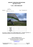
Inspection steps:
1. Fully assemble the glider ready for flight.
2. Pull the VG on full, until the VG rope stops.
3. Place the protractor/level on the underside of the keel between the cross bar straps as shown
in the following photograph. Do not move the glider from this position.
4. Raise the rear keel to horizontal as 0° is a convenient reference point.
Figure 20 Setting Reference Keel Angle
Issue Date: May 2007 Rev 1
Page 27
C4 OWNER and SERVICE MANUAL
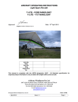
5. With the access zips to the washout struts closed, place the protractor/level on the underside
of the washout struts so that it sits with good contact (pressing through the sail) as shown in
the following photograph. The wing being measured will need to be raised so that any slack
is removed from the side wire. Measure and record at each of the washout strut locations as
described in the table below.
Figure 21 Measuring Washout Strut Angle
The table below indicates the minimum differential angle for each of the washout struts referenced
to the keel. Compare the measurements taken to the certified angles in the applicable table. Make
adjustments to raise the struts as required.
As a guide for the magnitude of adjustment:
• the inboard struts change approximately 0.5° per revolution of the threaded strut cone.
• the outboard struts change approximately 1° per revolution of the threaded strut cone.
Strut
Glider model
C4-13
C4-13.5
C4-14
Inboard
Outboard
VG on
5.1°
5.8°
7.4°
VG on
10.5°
12.1°
13.5°
Table 3 Washout Strut Angles, All Models
Issue Date: May 2007 Rev 1
Page 28
C4 OWNER and SERVICE MANUAL
How to make a change to the angle of a washout strut:
1. Swing the strut out from the sail.
2. Remove the split ring from the clevis pin. These parts are shown in Figure 11 (the pin locks
the adjuster cone and the strut together).
3. Remove the clevis pin.
4. To raise the trailing edge, view the washout strut from the rear, rotate the threaded cone
anticlockwise until the clevis pin hole reappears, this occurs in 1/2 turn increments.
To lower the trailing edge, view the washout strut from the rear, rotate the threaded cone
clockwise until the clevis pin hole reappears, this occurs in 1/2 turn increments.
5. Replace the clevis pin and split pin.
6. Replace the strut in the sail and capture it by doing the zipper up.
7. Tap the sail from above to jiggle the strut into its flattest position. The strut angle is now
ready to be sighted and test flown or re-measured (as appropriate).
When making strut adjustments for a turn, it is wise to visually sight the struts to check for gross
changes before test flying. To sight the strut settings, stand in front of the glider with the keel
horizontal & holding the nose wires. Slowly rotate the nose forward and backward, notice when the
trailing edge of each of the strut locations comes into and out of view.
ROLL/YAW TRIM
Turns in gliders occur when they are asymmetrical. If you have a turn in your glider you should
confirm that the seven possible variables outlined at the beginning of this section have been
checked.
The following tables outline procedures for adjustments. Adjustments should be made to the glider
in the sequence as listed. The glider should be tuned firstly in the VG off setting and then checked
with the VG ½ and full on. If necessary the sprogs must be tuned as outlined in the second table.
NOTE: We refer to the fast wing as the wing on the high side of the turn i.e. The right wing is the
fast wing if the wing is turning left and vice versa.
The tuning table refers to rotation of eccentric rings when viewed from the rear of the leading edge.
This is when standing at the wingtip and looking towards the nose of the wing.
Issue Date: May 2007 Rev 1
Page 29
C4 OWNER and SERVICE MANUAL
ROLL TRIM ADJUSTMENTS
MILD TURN VG OFF
ADJUSTMENTS WHEN THE GLIDER IS CONFIGURED VG OFF TO 1/2 ON
ADJUSTMENT METHOD
Remedy left turn
DIFFERENTIAL BATTEN TENSION.
Increase tension on last 5
If the turn is mild, then increasing and decreasing the
battens on left hand side
batten tension on either side can adjust it. If you increase
by 2 turns at a time.
the tension on the slow side you are effectively putting
more camber in the airfoil therefore creating more lift on
Decrease tension on last
that side.
5 battens on right hand
side by 1 turn at a time.
If you decrease the tension on the fast side you are
decreasing the camber and reducing the amount of lift.
The batten hinge clip can be rotated clockwise to
decrease tension or anti-clockwise to increase tension.
TIP PLUG ADJUSTMENT (TIP UP).
If further adjustment is required the tip angle on the fast
wing is raised. The tip plug can be rotated to raise or lower
the tip angle on either wing. To raise the tip angle on the
fast wing access the fibreglass tip bung through the zip at
the end of the leading edge tube. Remove the Philips
screw and adjust as outlined.
The standard setting is 1 hole from the zero hole for the
C4-all sizes. The fitting should not be adjusted more than
two holes from the standard position per adjustment.
Note that the direction of rotation varies according to the
two tip geometries used according to the serial number on
the glider.
Reinstall the screw once adjustment is made.
TIP PLUG ADJUSTMENT (TIP DOWN)
If the turn persists the tip angle can be lowered on the
slow wing. Access the fibreglass tip bung through the zip
at the end of the leading edge tube. Remove the Philips
screw and adjust as outlined.
The standard setting is as above. The fitting should not be
adjusted more than two holes from the standard position
per adjustment.
Reinstall the screw once adjustment is made.
Remedy right turn
Decrease tension on last 5
battens on left hand side
by 1 turn at a time.
Increase tension on last 5
battens on right hand side
by 2 turns at a time.
(For serial numbers up to
and including
C4-13:24 C4-14:20):
Rotate the right tip fitting
anti clockwise one hole at
a time, as viewed from the
rear of the leading edge.
(For serial numbers up to
and including
C4-13:24 C4-14:20):
Rotate the left tip fitting
clockwise one hole at a
time, as viewed from the
rear of the leading edge.
(For serial numbers
greater than and including
C4-13:25, C4-13.5:1, C414:21):
Rotate the right tip fitting
clockwise one hole at a
time, as viewed from the
rear of the leading edge.
(For serial numbers up to
and including
C4-13:24 C4-14:20):
Rotate the left tip fitting
anti clockwise if viewed
from the rear of the leading
edge one hole at a time.
(For serial numbers greater
than and including
C4-13:25, C4-13.5:1, C414:21):
Rotate the left tip fitting anti
clockwise one hole at a
time, as viewed from the
rear of the leading edge.
(For serial numbers up to
and including
C4-13:24 C4-14:20):
Rotate the right tip fitting
clockwise one hole at a
time, as viewed from the
rear of the leading edge.
(For serial numbers
greater than and including
C4-13:25, C4-13.5:1, C414:21):
Rotate the left tip fitting
clockwise one hole at a
time, as viewed from the
rear of the leading edge.
Use the "Y" tool to rotate
the right step down ring
anti-clockwise one hole, as
viewed from the rear of the
leading edge. This raises
the RHS rear leading edge.
(For serial numbers greater
than and including
C4-13:25, C4-13.5:1, C414:21):
Rotate the right tip fitting
anti clockwise one hole at
a time, as viewed from the
rear of the leading edge.
Use the "Y" tool to rotate the
left step down ring
clockwise one hole, as
viewed from the rear of the
leading edge. This raises
the LHS rear leading edge.
MORE SIGNIFICANT
TURN VG OFF
REAR SECTION ADJUSTMENT.
If the turn still persists after the tip plug rings have been
rotated the front leading edge step down rear eccentric
ring can be adjusted. The angle that the rear section
protrudes from the front section can be altered by rotation
of the outer eccentric (plastic) ring. The location of this
ring is fixed with a small screw. Remove screw and
reinstall once adjustment is made.
If the glider tends to turn the opposite direction after the rear section adjustment, the tip plugs should be adjusted to straighten
the glider.
Table 4 Tuning Matrix - Frame
Issue Date: May 2007 Rev 1
Page 30
C4 OWNER and SERVICE MANUAL
SPROG ADJUSTMENT FOR SYMMETRY
(“Sprog” refers to the wire braced washout struts)
MILD TURN VG OFF DURING
STRAIGHT ARM DIVE
ADJUSTMENTS WHEN THE GLIDER IS CONFIGURED VG OFF, TURN DURING STRAIGHT ARM DIVE
ADJUSTMENT METHOD
Remedy for left turn
Remedy for right
turn
IN OARD SPROG ADJUSTMENT. The glider should
Raise the right sprog by Raise the left sprog
be assembled with the VG off. Unzip the outer sprog
rotating the cone
by rotating the cone
and fold forward. Remove the ring and clevis pin from anticlockwise by 1/2
anticlockwise by 1/2
the front of the sprog tube. Make appropriate
turn.
turn.
adjustment and install clevis pin and ring. Install
sprog.
INBOARD SPROG ADJUSTMENT. If the glider still
Lower the left sprog by
Raise the left sprog
turns the opposite sprog can be lowered as
rotating the cone
by rotating the cone
described.
clockwise by 1/2 turn.
anticlockwise by 1/2
turn.
MILD TURN VG ON
ADJUSTMENTS WHEN THE GLIDER IS CONFIGURED VG 1/2 ON TO FULL ON
ADJUSTMENT METHOD
Remedy for left turn
OUTBOARD SPROG ADJUSTMENT. The glider
should be assembled with the VG off. Unzip the outer
sprog and fold forward. Remove the ring and clevis
pin from the front of the sprog tube. Make appropriate
adjustment and install clevis pin and ring. Install
sprog.
OUTBOARD SPROG ADJUSTMENT. If the glider still
turns the opposite sprog can be lowered as
described.
Raise the right sprog by
rotating the cone
anticlockwise by 1/2
turn.
Lower the left sprog by
rotating the cone
clockwise by 1/2 turn.
Remedy for right
turn
Raise the left sprog
by rotating the cone
anticlockwise by 1/2
turn.
Raise the left sprog
by rotating the cone
anticlockwise by 1/2
turn.
Table 5 Tuning Matrix - Sprogs
If after following the procedure as outlined above the glider still tends to roll one way, please contact
your AirBorne dealer or call the AirBorne factory.
Issue Date: May 2007 Rev 1
Page 31
C4 OWNER and SERVICE MANUAL
TIP PLUG ADJUSTMENT
REAR SECTION ADJUSTMENT
LOCATING
SCREW
REFERENCE
LINE
Figure 22 Leading Edge End Cap
Figure 23 Leading Edge Step Down
TIP LEVER ADJUSTMENT
FIGURE 1
POSITION B
POSITION A
REFERENCE
POINTS
POSITION D
POSITION C
INSERT ROTATED TO ACHIEVE
ADDITIONAL ADJUSTMENT
Figure 24 Tip Lever Adjustments
The following table shows standard sail position and variations to the standard setting.
APPLICABLE GLIDER
STANDARD POSITION
C4-13: 001 onwards
C4-13.5: 001 onwards
C4-14: 001 onwards
Table 6 Tip Lever Adjustments
Position D
ADJUSTMENTS (setting and distance from
standard position D)
Position C +7mm (slacken)
Position A +4mm (slacken)
Position B -3mm (tighten)
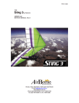
Adjusting Batten Tension
Figure 25 Standard Batten Tension
The standard batten tension is defined by the
angle that the batten tip sits freely when it is not
locked. Battens on either side are locked.
Inner Battens: 20°
Tip Batten: 45°
Issue Date: May 2007 Rev 1
Page 32
C4 OWNER and SERVICE MANUAL
HANDLING AND PERFORMANCE TUNING
The following table is designed to allow a pilot to reference methods of tuning the C4 to suit the
individual. Varying wing loading will affect the way the glider behaves in pitch and roll trim. For
example, a heavier loaded glider will tend to increase the flex in the leading edge tube causing more
washout. This increase in washout will tend to make the glider more spirally stable. A lightly loaded
glider will tend to be less spirally stable requiring more high siding from the pilot.
Adjustments are described assuming that the glider is straight and all adjustments are symmetrical.
TUNING
CENTER OF GRAVITY
TIP PLUGS
Rotating the tip plug for the
tip wand to stand up or
down. See Note 1.
INNER RING
Rotating the inner rings
down results in an increase
in the leading edge dihedral
ie Left leading edge inner
ring clockwise & Right
leading edge inner ring anti
clockwise
LEADING EDGE TENSION
HANDLING
Increase in pitch pressure
when CG moved rearward.
Decrease in pitch pressure
when moved forward.
Rotating the tip plugs for tip
wands pointed up reduces
high siding on a bank.
Rotating the tip plugs for tip
wands pointed down
increases the amount of
high siding required.
Rotating the inner ring
down reduces high siding
on a bank.
PERFORMANCE
No change.
No change.
Slightly reduced
performance.
BAR PRESSURE
Increase in pitch pressure
when CG moved rearward.
Decrease in pitch pressure
when moved forward.
Increase in bar pressure.
Slightly better performance.
Reduction in bar pressure.
Does not affect
performance.
No change with small
adjustments.
Rotating the inner ring up
increases the amount of
high siding required.
Does not affect
performance.
No change with small
adjustments.
Increase in leading edge
tension slows roll rate.
A slight increase may
improve performance but
over tensioning will cause
the tip to bend up
effectively reducing
performance.
Loss of performance if
tension is reduced to the
point where the leading
edge starts to deform.
No change with small
adjustments.
Decrease in leading edge
tension improves roll rate.
Larger changes reduce the
crispness of the landing
flare.
No change with small
adjustments.
Table 7 Handling and Performance Tuning
Note 1. Tip geometry varies between early and more recent models.
For early models, the tip rod is located on the forward side of the leading edge. Rotating the right
tip clockwise lowers the tip rod (providing anhedral (down)).
For late models, the tip rod is located on the rearward side of the leading edge. Rotating the right tip
clockwise raises the tip rod (providing dihedral (up)).
Issue Date: May 2007 Rev 1
Page 33
C4 OWNER and SERVICE MANUAL
Section 13
PERIODIC INSPECTIONS and MAINTENANCE
MAINTENANCE SCHEDULE
1 – Clean and service, 2 – Check as directed, 3 – Check for security, cracks, wear and faulty operation, 4 - Remove, inspect
and replace if necessary, 5 - Recommend replacement or overhaul.
MAINTENANCE REQUIREMENT
Maintenance Period
Period >
Daily Monthly Three
Six
Every Every 2 Every 4
Months Monthly Year
Years Years
Flying
1
10
30
50
100
200
400
Days >
Wing fabric deterioration and tears
2
2
2
2
4
5
Wing fabric stitching
2
2
2
2
2
Wing fabric attachment points
3
3
3
3
3
3
Batten clip fittings
3
3
3
3
4
4
Check battens against template supplied
2
2
2
2
2
Wing wires and attachment fittings, including sprog wires
2
3
3
4
5
5
5
Check leading edges, keel & A frame for straightness,
2
2
2
2
4
4
4
dents and corrosion
Check leading edges, keel & A frame structural members
2
2
2
2
4
4
4
and check for fatigue cracks radiating from drilled holes.
Check centre junction and carbon spars (See notes)
2
2
2
2
4
4
4
Check cross tube leading edge junction
2
2
2
2
3
3
3
(Remove hinge bolt and inspect bushes, bolt and hole)
4
5
5
5
Check sprog assemblies including rod ends, clevis pins etc
2
2
2
2
2
2
2
Check inspection zips
2
2
2
2
2
2
Check variable geometry, pulleys and cleats
2
3
3
3
4
4
5
All bolts, nuts, washers & safety pins. At least one thread
2
2
2
2
2
2
2
showing outside each nut.
Check hang straps and karabiners for wear or damage
2
2
2
2
4
5
5
Check saddles and fittings for cracks
2
2
2
4
4
5
Table 8 Periodic Maintenance
It is recommended that:
• Items marked 1,2 and 3 should be performed by the owner of the glider;
• Items marked 4 be performed by the owner in conjunction with another pilot; and
• Items marked with a 5 be performed by AIRBORNE or an accredited AIRBORNE service
agent.
LOG BOOK
When maintenance is performed always check the appropriate square and make an entry in the
maintenance log at the rear of this manual.
Issue Date: May 2007 Rev 1
Page 34
C4 OWNER and SERVICE MANUAL
NOTES ON PERIODIC INSPECTIONS
AIRFRAME TUBING
Installation & Removal
When removing tubing do not bend or force tubes. If resistance is encountered stop and check for
the cause. Do not force the tube.
Inspection
Inspect tubing for cracks, damage from abrasion, elongated holes or distortion in tube surface. Never
attempt to repair tubing, always replace with new part. Inspect tubing for corrosion inside and out. If
corrosion is present the component should be replaced.
Replacement
Aluminium tube comes in many different sizes and grades. It is important that the correct
replacement parts are used.
CARBON CROSS TUBES
Installation & Removal
To comprehensively check the carbon spars and junction, the sail should be removed from the
airframe as outlined in this manual.
Inspection
The carbon cross tubes should be thoroughly inspected for cracks. The aluminium plug, which is
bonded into the carbon tube at the centre section, should also be thoroughly checked for damage or
cracking at the bond line. A torch should be used to check that the tubes show no signs of damage
on the inside.
BOLTS
Installation & Removal
After tightening, all bolts should have at least one and a half to two threads showing.
All self-locking nuts should not be installed more than two times.
Be sure not to over torque bolts when installing.
Inspection
Check bolts for worn shanks, bad threads or corrosion.
Issue Date: May 2007 Rev 1
Page 35
C4 OWNER and SERVICE MANUAL
SAILS
Sail Inspection
Check for tears in the sailcloth and or any loose or unravelled seams.
Check all inspection zippers to see that they function smoothly and close completely.
Inspect tip webbing for damage.
Sail may be repaired with appropriate sail tape or a sewn on patch. AIRBORNE or an authorised
agent should be consulted about sail repairs. Keep the sail clean of oil and dirt by washing the sail
with soap and water. Keep the sail covered when not in use.
Sails shrink over a period of time due to exposure to the elements (approx 5-10mm per year for high
exposure wings).
This results in an increase in leading edge tension and a decrease in trailing edge tension. The sail
leading edge tension will have to be adjusted over the life of the sail in order to retain its
performance. Refer to fig 1 page 31.
CONTINUED EXPOSURE TO SUN DRAMATICALLY SHORTENS THE LIFE OF SAILS
- possibly to as little as six months.
INSPECTION AFTER HARD LANDING
It is necessary to conduct a detailed inspection following any unusual stressing of the hang glider.
This full inspection should include all details listed for the six monthly maintenance.
The inspection should be noted in the logbook, and any replacement recorded.
DEFECT REPORTS
Details of any defect which develops in service and which, if kept uncorrected, would compromise
the continued safe operation of the hang glider should be reported to AIRBORNE as soon as
practicable.
Issue Date: May 2007 Rev 1
Page 36
C4 OWNER and SERVICE MANUAL
Section 14
TRANSPORTATION AND STORAGE
Avoid damage to your glider by using well-padded racks. Careless transportation can cause
considerable damage to your glider.
We recommend that you support the glider in at least 3 places to spread the load. The glider should
be transported with the control frame down to minimise the chance of damage to the cross tubes.
Flat straps should be used for tie downs to avoid damage to leading edge mylar.
Store the glider in a dry room off the ground. Air the glider out regularly to avoid mildew, and never
store wet.
Issue Date: May 2007 Rev 1
Page 37
C4 OWNER and SERVICE MANUAL
Section 15
MAINTENANCE RECORD
Date
Details of Repair or Maintenance
Carried out by:
Table 9 Maintenance Log
Issue Date: May 2007 Rev 1
Page 38
C4 OWNER and SERVICE MANUAL
Section 16
HANG GLIDER COMPLIANCE SCHEDULES
GLIDER MODEL: C4 13
MANUFACTURED BY:
AIRBORNE WINDSPORTS Pty Ltd
NOTE: These specifications are intended only as a guideline for determining whether a given glider
is a certified model and whether it is in the certified configuration.
Be aware however, that no set of specifications, however detailed, can guarantee the ability to
determine whether a glider is the same model, or is in the same configuration as was certified, or has
those performance, stability, and structural characteristics required by the certification standards. An
owner's manual is required to be delivered with each HGMA certified glider, and it is required that it
contain additional airworthiness information.
Weight of glider with all essential parts and without cover bags and nonessential parts.
Leading Edge Dimensions
Nose Plate anchor hole to crossbar attachment hole
Nose Plate anchor hole to rear sail attachment point
Outside diameter at nose
Outside diameter at cross bar
Outside diameter at rear sail attachment point
Crossbar Dimensions
Overall pin to pin length from leading edge attachment point to hinge bolt
at glider centre line
Largest outside diameter
Keel dimensions
The cross bar centre load bearing pin
The pilot hang loop
Fwd
distance from forward nose plate hole
Rear
Sail Dimensions
Chord length at 3 ft outboard of centre line
Chord length at 3 ft inboard of tip
Span (extreme tip to tip)
Location of Information Placard
Location of Test Fly Sticker
Recommended Pilot Hook in Weight Range
Recommended Pilot Proficiency
Metric
33 kg
Imperial
73 lbs
3080 mm
5490 mm
60 mm
62 mm
12 mm
121.26”
216.14”
2.36”
2.44”
1.77”
2871 mm
113.03”
75 mm
2.95”
760 mm
1245 mm
1295 mm
29.92”
49.02”
50.98”
1620 mm
63.78”
1020 mm
40.18”
9600 mm
377.95 “
Front RHS crossbar centre
Front RHS crossbar centre
55-80 kg
121-176 lbs
Advanced
Table 10 Compliance Schedule C4-13
NB: Conversions * 0.4536 kg/pound * 25.4 mm/inch * 1.609km / mile
Issue Date: May 2007 Rev 1
Page 39
C4 OWNER and SERVICE MANUAL
GLIDER MODEL: C4 13.5
MANUFACTURED BY:
AIRBORNE WINDSPORTS Pty Ltd
NOTE: These specifications are intended only as a guideline for determining whether a given glider
is a certified model and whether it is in the certified configuration.
Be aware however, that no set of specifications, however detailed, can guarantee the ability to
determine whether a glider is the same model, or is in the same configuration as was certified, or has
those performance, stability, and structural characteristics required by the certification standards. An
owner's manual is required to be delivered with each HGMA certified glider, and it is required that it
contain additional airworthiness information.
Weight of glider with all essential parts and without cover bags and nonessential parts.
Leading Edge Dimensions
Nose Plate anchor hole to crossbar attachment hole
Nose Plate anchor hole to rear sail attachment point
Outside diameter at nose
Outside diameter at cross bar
Outside diameter at rear sail attachment point
Crossbar Dimensions
Overall pin to pin length from leading edge attachment point to hinge bolt
at glider centre line
Largest outside diameter
Keel dimensions
The cross bar centre load bearing pin
The pilot hang loop
Fwd
distance from forward nose plate hole
Rear
Sail Dimensions
Chord length at 3 ft outboard of centre line
Chord length at 3 ft inboard of tip
Span (extreme tip to tip)
Location of Information Placard
Location of Test Fly Sticker
Recommended Pilot Hook in Weight Range
Recommended Pilot Proficiency
Metric
34 kg
Imperial
75 lbs
3080 mm
5490 mm
60 mm
62 mm
12 mm
121.26”
216.14”
2.36”
2.44”
1.77”
2871 mm
113.03”
75 mm
2.95”
760 mm
1245 mm
1295 mm
29.92”
49.02”
50.98”
1688 mm
66.5”
1063 mm
41.9”
10000 mm
393.7 “
Front RHS crossbar centre
Front RHS crossbar centre
70-110 kg
154– 220 lbs
Advanced
Table 11 Compliance Schedule C4-13.5
NB: Conversions * 0.4536 kg/pound * 25.4 mm/inch * 1.609km / mile
Issue Date: May 2007 Rev 1
Page 40
C4 OWNER and SERVICE MANUAL
GLIDER MODEL: C4 14
MANUFACTURED BY:
AIRBORNE WINDSPORTS Pty Ltd
NOTE: These specifications are intended only as a guideline for determining whether a given glider
is a certified model and whether it is in the certified configuration.
Be aware however, that no set of specifications, however detailed, can guarantee the ability to
determine whether a glider is the same model, or is in the same configuration as was certified, or has
those performance, stability, and structural characteristics required by the certification standards. An
owner's manual is required to be delivered with each HGMA certified glider, and it is required that it
contain additional airworthiness information.
Weight of glider with all essential parts and without cover bags and non
essential parts.
Leading Edge Dimensions
Nose Plate anchor hole to crossbar attachment hole
Nose Plate anchor hole to rear sail attachment point
Outside diameter at nose
Outside diameter at cross bar
Outside diameter at rear sail attachment point
Crossbar Dimensions
Overall pin to pin length from leading edge attachment point to hinge bolt
at glider centre line
Largest outside diameter
Keel dimensions
The cross bar centre load bearing pin
The pilot hang loop
Fwd
distance from forward nose plate hole
Rear
Sail Dimensions
Chord length at 3 ft outboard of centre line
Chord length at 3 ft inboard of tip
Span (extreme tip to tip)
Location of Information Placard
Location of Test Fly Sticker
Recommended Pilot Hook in Weight Range
Recommended Pilot Proficiency
Metric
36 kg
Imperial
79. lbs
3375 mm
5955 mm
60 mm
62 mm
12 mm
132.87”
234.45”
2.36”
2.44”
0.47”
3141 mm
123.66”
75 mm
2.95”
845 mm
1385 mm
1335 mm
33.27”
48.62”
52.56”
1780 mm
70.08”
1120 mm
44.09”
10400 mm
409.45“
Front RHS crossbar centre
Front RHS crossbar centre
85-120 kg
187-265 lbs
Advanced
Table 12 Compliance Schedule C4-14
NB: Conversions * 0.4536 kg/pound * 25.4 mm/inch * 1.609km/mile
Issue Date: May 2007 Rev 1
Page 41