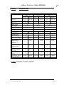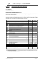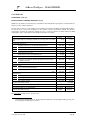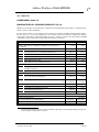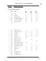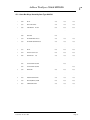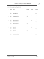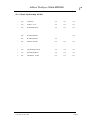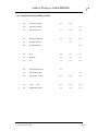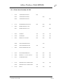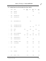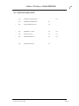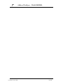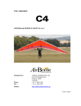
1
THE
SHARK
OWNER/SERVICE MANUAL
by
AirBorne
AirBorne WindSports Pty Ltd
22/30 KALAROO RD, REDHEAD 2290 NSW, AUSTRALIA
TEL(02) 49 449 199
FAX(02) 49 449 395
e-mail [email protected]
AirBorne WindSports- Shark MANUAL
TABLE OF CONTENTS
Section 1
DESIGN FEATURES4
Section 2
SPECIFICATIONS6
Section 3
OPERATING LIMITATIONS7
Section 4
WARRANTY STATEMENT8
Section 5
ASSEMBLY PROCEDURE9
Section 6
PRE-FLIGHT INSPECTION11
Section 7
BREAK DOWN PROCEDURE 13
Section 8
ASSEMBLY FROM SHIPPING LENGTH14
Section 9
FLIGHT TECHNIQUE15
Section 10
TUNING17
Section 11
PERIODIC INSPECTIONS and MAINTENANCE20
Section 12
TRANSPORTATION AND STORAGE23
Section 13
MAINTENANCE RECORD24
Section 14
HANG GLIDER COMPLIANCE SCHEDULES25
Section 15
ASSEMBLY DRAWINGS28
Issue Date: 14 June 1995
Page 4
AirBorne WindSports- Shark MANUAL
Section 1
DESIGN FEATURES
The Shark is the latest hang glider from AirBorne Windsports, and is the result of continued
testing and refinement by AirBorne’s research and development team.
The philosophy behind the development of the Shark was to design a glider which has an
increase in all round performance without complicating the set up or compromising the handling
characteristics. We believe we have succeeded in all aspects.
At a first glance the Shark looks different. The main sail battens are enclosed inside the sail. The
battens are tensioned with an internal spring system which not only is faster to load but is much
cleaner both aerodynamically and visually. The tip strut requires more tension than the other
mainsail battens and utilises an over centre lever to obtain the required tension. The upper and
lower surface at the tip has been faired down so that both surfaces meet.
The leading edge mylar pocket is wrapped further around the leading edge which improves the
surface airflow. Testing has confirmed a performance increase due partly to the increased
leading edge wrap.
As you start to look closer at the Shark you will find several innovative features inside the sail.
The standard VG system which requires the X-Bars to move forward and backward has been
replaced by a cam system which operates at the X-Bar leading edge junction. The cam plate is
operated by a wire which runs to the nose of the glider. The plate pivots around the X-Bar and
pushes the leading edge out which tightens the sail.
Several advantages are gained from the X-Bar cam system:
The side wire attachment point is inboard of the cam which allows the side wires to be tight in all
VG settings. Tight rigging is a major benefit during launch and general ground handling.
The cross bar centre hinge point can be moved further back as it is not required to move for the
VG system. The result is a stronger compression member because the X-Bars are straighter and
slightly shorter. Straighter cross bars also reduces the load on the pull back wire which results in
easier tensioning. The X-Bar junction also has a ball and socket system which increases the
cross bar strength by removing the acentric loads caused by the X-Bar hinge.
Our new X-Bar and leading edge geometry allow the top of the control bar to be moved rearward
approximately 150mm whilst still allowing the glider to be assemble flat on the ground. Moving
the top of the control bar back improves the static balance and also improves the flair authority.
Imported 7075-T6 Aluminium is used in the airframe construction of the Shark. The battens are
also made from 7075-T6 aluminium which require almost no maintenance. The overall result is a
very strong glider with minimum weight.
The Shark retains the tapered fibreglass rear leading edge with a 60mm 7075 front leading edge
which provides an extremely stiff leading edge at the X-Bar junction out to the mid span region.
The tapered fibreglass rears allows optimum flex at the tip.
Pitch stability has been achieved using a 2 x 2 split luff line system to minimize drag and an
internal dive stick constructed from carbon fibre. The carbon dive stick is extremely strong and
light weight.
Issue Date: 14 June 1995
Page 5
AirBorne WindSports- Shark MANUAL
The Shark maintains all the fast set-up features which have become a trade mark of AirBorne
hang gliders. It can, as with all AirBorne gliders, be assembled flat or on the control frame.
AirBorne's quality assurance program,which is unique to the industry, ensures that every glider
is built in accordance with the standard it was designed to. This gives even the most experienced
pilot a sense of security when flying an AirBorne glider.
We hope that you have hours of great flying with your new glider. Fly high and safely.
Rick Duncan, Russell Duncan, Shane Duncan, Rob Hibberd and Paul Mollison
AirBorne WindSports
Issue Date: 14 June 1995
Page 6
AirBorne WindSports- Shark MANUAL
Section 2
SPECIFICATIONS
SHARK 132
SHARK 144
SHARK 156
METRIC
IMPERIAL
METRIC
IMPERIAL
METRIC
IMPERIAL
SAIL AREA
12.3 sq
meter
132 sq ft
13.4 sq
meter
144 sq ft
14.6 sq
meter
156 sq ft
WING SPAN
9.36
30.70 feet
9.71 m
31.86 feet
10.36 m
34.00 feet
ASPECT RATIO
NOSE ANGLE
7.2
7.2
7.3
128 degrees
128 degrees
128 degrees
82%
82 %
82 %
29
29
31
DOUBLE SURFACE %
BATTENS
GLIDER WEIGHT
28 kg
ASSEMBLY TIME
62 pound
32kg
7 min
71 pound
35 kg
7 min
77 pound
7 min
PACK UP LENGTH
5.3 meter
17.39 feet
5.5 meter
18.05 feet
5.9meter
19.4 feet
SHORT PACK LENGTH
3.7 meter
12.14 feet
3.9 meter
12.80 feet
4.2 meter
13.77 feet
RECOMMENDED PILOT
HOOK IN WEIGHT
RANGE (Includes
Equipment)
50-85 kg
110-187
pounds
65-105 kg
143-232
pounds
80-125 kg
176-276
pounds
MINIMUM SPEED (At
max recommended
weight)
40 km/h
25 mph
40 km/h
25 mph
43 km/h
27 mph
MAXIMUM SPEED (At
min weight)
71 km/h
44 mph
78 km/h
48 mph
79 km/h
49 mph
VNE (Velocity Never to
Exceed)
85 km/h
53 mph
85 km/h
53 mph
85 km/h
53 mph
VA ( Maximum rough air
manouvering speed)
74 km/h
46 mph
74 km/h
46 mph
74 km/h
46 mph
Conversions: * 2.205kg/pound * 25.4mm/inch * 1.609km/mile
* Va = Test speed x .707 * Vne = Test Speed x.816
Issue Date: 14 June 1995
Page 7
AirBorne WindSports- Shark MANUAL
Section 3
OPERATING LIMITATIONS
WARNING
Hang Gliding is a high risk sport. The safe operation of this hang glider ultimately rests with
you, the pilot. We believe that in order to fly safely you must maturely practice the sport of
hang gliding. You should never fly this hang glider beyond the placarded limits.
The velocity never to exceed (VNE) for your glider is given in Section 2, as is the maximum
speed for manoeuvres or flying in rough air (VA). The indicated airspeeds given are for
calibrated instruments mounted on, or near, the base bar of the control frame. During your
initial flights on the glider it is recommended that you fly with an airspeed indicator until you
are able to recognise the control feel that produces the airspeeds shown.
Flight operations should be limited to non-aerobatic manoeuvres where the pitch angle
does not exceed 30 degrees up or down to the horizon and where the bank angle does not
exceed 60 degrees.
Aggressive stalls and spins should not be attempted. Operations outside the recommended
flight envelope, such as aerobatic manoeuvres or erratic pilot technique may ultimately
produce equipment failure.
Your glider was designed for foot launched soaring and should not be flown by more than
one person at a time. It should not be flown backwards or inverted.
The setting up and breaking down of a hang glider, transportation on cars and flying itself,
will have an effect over time on its structural integrity. The glider will require maintenance
as outlined in the maintenance section of this manual. Like any aircraft safety depends on a
combination of careful maintenance and your ability to fly intelligently and conservatively.
The owner and operator must understand that due to inherent risks involved in flying a
hang glider, no warranty of any kind is made or implied against accidents, bodily injury and
death, other than those which cannot by law be excluded.
We hope that your new glider will provide you with many hours of safe flying.
AIRBORNE.
Issue Date: 14 June 1995
Page 8
AirBorne WindSports- Shark MANUAL
Section 4
WARRANTY STATEMENT
This warranty extends to new Hang Gliders and/or accessories and equipment manufactured by
AIRBORNE WINDSPORTS PTY LTD ("Airborne") and shall not embrace any other accessories
or equipment in the sale.
AIRBORNE warrants to the customer the hang glider and/or accessories manufactured or
supplied by AIRBORNE to be free from defect in material and workmanship under normal use
and service and of merchantable quality and fit the purpose for which they are ordinarily used.
This Warranty will apply for a period of ninety (90) days from the date of dispatch of the hang
glider not withstanding the number of hours flown but subject to the hang glider remaining the
property of the customer. This warranty does not exclude any rights implied in favour of any
customer by any applicable Federal and State legislation.
AIRBORNE will make good any parts required because of defective material or workmanship as
set out in the Warranty.
THE WARRANTY WILL NOT APPLY TO:
* Any mechanical adjustments, parts, replacements, repairs or other servicing that in the judgement of AIRBORNE
are made or should be made as maintenance.
* Any defect caused by any alteration or modification not approved by AIRBORNE.
* Any defect caused by the fitment of parts that are not made or approved by AIRBORNE.
* Any defect caused by misuse, accidents, negligence or failure to carry out proper maintenance service.
* Damage caused by continued operation of the hang glider after it is known to be defective.
* Any defect or consequential loss, damage or injury caused by overloading.
* Loss of use of the hang glider, loss of time, inconvenience, damages for personal injuries, loss of property or other
consequential damages.
* Failure due to wear and tear, accident, fire, incorrect or incomplete rigging and/or assembly, exposure to the
elements, operation outside the placarded limitations and repairs attempted or made other than by AIRBORNE or its
authorised agent.
AIRBORNE will replace, free of charge, any original part that is determined by AIRBORNE to be
defective under the terms of this Warranty and reserves the right to pay monetary compensation
or make good the defect in any manner it deems appropriate.
The customer is responsible for transporting the hang glider or parts to and from AIRBORNE or
its authorised agent when making claims under this Warranty. The hang glider or parts are at the
customer's risk whilst in transit to and fromAIRBORNE or its authorised agent.
NOTE: Warranty service is available to the customer from AIRBORNE WINDSPORTS PTY
LIMITED or authorised agent.
AIRBORNE WINDSPORTS
Issue Date: 14 June 1995
Page 9
AirBorne WindSports- Shark MANUAL
Section 5
ASSEMBLY PROCEDURE
The wing can be assembled in two positions, either lying flat or standing on the control frame.
Assembling the Shark on the control frame is the most popular method of assembly in light
winds. This method is preferable as the sail is less prone to being soiled or damaged during
assembly. In higher winds it is preferable to lay the glider flat for assembly with the nose into the
wind until ready to launch.
Our suggested sequence is as follows:
1)
UNZIP THE BAG. Lay the wing down with zip up and the nose facing
approximately 120 degrees from the wind direction. The nose should be facing
into the wind when assembling flat. Unzip the bag and un clip centre ties.
2)
ASSEMBLE CONTROL FRAME. Spread the control bar down tubes and
attach base bar to knuckle. The pip pin is then inserted with the cover firmly
secured. Check that all the rigging wires are outside the control frame.
3)
STAND GLIDER UP. Rotate the control frame to the vertical position and
rotate the wing 180 degrees so that it is sitting on the base bar. If assembling
flat ensure that control bar is central and the wires are not tangled.
4)
REMOVE BAG. Remove the glider bag and un clip remaining ties.
5)
SPREAD LEADING EDGES. Carefully spread both leading edges out half way
then spread leading edges to their approximate flying position.
IT IS ESSENTIAL THAT THE KEEL AND THE
LEADING EDGES ARE KEPT IN THE SAME
PLANE OR DAMAGE WILL RESULT.
6)
RAISE KING POST. Raise the kingpost and attach the reflex bridles.
7)
INSERT MAINSAIL BATTENS. Remove the battens from the bag. The red
battens are for the left side and the green for the right. Insert the battens from
the centre to the tip with gentle pressure, until the batten meets resistance.
Shake the sail at the trailing edge whilst maintaining gentle pressure on the
batten to allow the batten to be inserted over the cross bar. DO NOT FORCE
THE BATTENS! Locate batten in to sail pocket. It is advised not to insert the
last cambered tip batten and tip strut until the cross bars are tensioned.
8)
TENSION CROSS BARS. The cross bars are now tensioned by pulling the
webbing loop until the shackle is positioned on the Quick Clip. Ensure that the
catch is positively locked. When tensioning the glider lying flat the keel can be
raised slightly allowing the side flying wires to become looser.
9)
ATTACH REAR TOP WIRE. The rear top wire should now be attached to the
10)
LOAD TIP STRUTS. Insert the tip battens and tension tip struts. The tip strut
should be located on to the webbing loop on the trailing edge. The centre of
Issue Date: 14 June 1995
Page 10
rear Quick Clip blo
AirBorne WindSports- Shark MANUAL
the strut is now pushed towards the centre of the glider to tension.
11)
ATTACH FRONT FLYING WIRES. The ring on the front flying wires can now
be inserted in to the Quick Clip Block. Ensure that the catch is positively
locked. If the glider has been assembled flat it should now be lifted on to the
control frame. Be aware of the tip battens! Make sure you have a firm grip on
the keel when raising the nose from the flat position in strong winds.
12)
INSERT UNDER SURFACE BATTENS. (The rear keel can be popped off and
used to lift the rear of the glider in light wind conditions)The under surface
battens should be inserted past the hole in the sail and then pulled backwards
to the rear of the pocket
13)
INSERT NOSE BATTEN. Insert the nose batten tail end first and locate it on
the fitting on the front of the keel. A visual check of the variable geometry
system is advisable at this point.
14)
INSTALL NOSE FAIRING. Attach the nose fairing applying the top velcro first
then gently tension over the nose plates and attach the velcro to the
undersurface.
15)
PREFLIGHT INSPECTION. You are now ready for the wing pre-flight
inspection as outlined in the next section. It is imperative that you carry out this
inspection every time you rig and before you fly.
Issue Date: 14 June 1995
Page 11
AirBorne WindSports- Shark MANUAL
Section 6
PRE-FLIGHT INSPECTION
A thorough pre-flight inspection is mandatory for any aircraft, and the best technique is a circular
walk around the wing. The nose area is the ideal place to start your pre-flight check, followed by
each assembly point.
Keep in mind the three most critical set up areas:
1)
The nose quick clip
2)
Control bar base tube connecters.
3)
The cross bar tension quick clip.
Starting at the nose we suggest the following checklist (ensuring all bolts and fasteners have the
appropriate thread protruding beyond the nut).
1)
Check the nose plate assembly ensuring that the king post wire is not kinked.
Sight along both leading edges checking for similar curves.
2)
Walk towards the tip feeling for dents in the leading edge.
3)
Check cross bar/leading edge junction through the zipper access. Check cam
plate is in order. Ensure that the pivot bolts are secure.
4)
Check sail tip webbing is undamaged and is located properly on the fitting.
Ensure tip fitting pins are fully inserted into the tip bung and velcro is in place.
5)
Crouch down and lift tip to eye level to inspect that the tip strut and dive stick
are properly located and that the rear leading edge is undamaged.
6)
Walk towards the keel checking all battens are secured and correctly loaded.
7)
Check all luff lines attachments are in order.
8)
Check that the cross bar retaining shackle and rear top wire are secured on
the quick clip.
9)
Check the rear top rigging and that the reflex bridle carabina is properly closed.
10)
Check king post base.
11)
Repeat steps #2 - #7 for the other side wing in reverse order.
12)
Check all lower rigging is correctly routed and free from damage. The most
likely area for damage on wires is around the swage and thimble area.
13)
Check Control Bar corners are correctly assembled with pip pin and cover in
place.
14)
Ensure hang loop is secure and in good order. Check attachment point on
Issue Date: 14 June 1995
Page 12
AirBorne WindSports- Shark MANUAL
15)
King Post.
Check control bar top assembly and ensure that the down tubes are straight.
16)
Unzip undersurface and check cross bar hinge and retaining strap. Ensure
cross bar ball and socket is properly located and cover is not caught in the
joint. Operate VG system to ensure it is functioning properly. Check all VG
wires are in good order and are not twisted or kinked.
17)
Ensure that the double surface is zipped up and the nose fairing is secured.
18)
Clip your harness into the main and back up hang loops and perform a "hang
check". Make sure that your harness is the correct distance from the base bar,
your leg loops are secure and your carabina is locked.
6.0.1 Hang Glider Daily Inspection
Inspection of the following items after every assembly of the glider is required:
• Check for bends, dents, scratches in all tubes;
• Check wire ends for bolt and/or other fastener security;
• Check wires for twisted or jammed thimbles;
• Check wires are free of kinks, frays, abrasions, broken strands etc;
• Nose plate connections;
• Tips secure;
• Battens secure;
• A-frame connections at the top and base on both sides;
• Variable geometry operation (full and free movement);
• Rear keel connections;
• Cross-bar tension wire;
• Cross-bar (free floating);
• King post connections;
• Luff Lines - attached and tension correct;
• Sail condition;
• Harness straps and webbing secure, height adjustment correct;
• Emergency parachute secure, attached and operating handle accessible.
Issue Date: 14 June 1995
Page 13
AirBorne WindSports- Shark MANUAL
Section 7
BREAK DOWN PROCEDURE
To break down your Shark, just reverse the set-up procedure steps as described. Included here
are a few guidelines to follow which will save you time and prevent potential wear areas on your
sail.
It is possible to leave the nose batten in during daily operations! It is, however, important to
remove the nose batten from the fitting on the front of the keel.
1)
Remove nose fairing.
2)
Remove tension from tip strut and remove undersurface battens.
3)
Let off the sail tension and pull each wing in slightly. Pull out all main sail
battens.
4)
Attach top control bar padding.
5)
Disconnect reflex bridle and attach rear quick clip padding.
6)
Fold both wings in symmetrically, bringing both leading edges back at the
same time. Disconnect carbon dive sticks.
7)
Roll the sail up from the last luff line. Roll the luff lines into the sail. This will
avoid tangling of the luff lines during the set up procedure. One tie should be
wrapped around the keel and leading edge to hold them together whilst the
other side wing is rolled.
8)
Place padding over the end of the keel and quick clip block.
9)
Ensure that the sail is rolled into the leading edge pockets. It is important that
the ties are not over tensioned as this can damage the mylar insert.
10)
Place glider bag in position.
11)
Roll glider over, undo control bar pip pin. Fold base bar rearward. Attach base
bar padding around down tube base. Place padding over the end of the base
bar. Undo the two centre ties and fold the control bar down between the
leading edge pockets. Secure the centre ties and zip up bag.
For de-rigging flat, attach top control bar padding. Undo nose wires and remove nose fairing. Pull
wing forwards then follow steps as above.
If resistance is encountered during any phase of set up or break down procedure stop and
investigate.
Issue Date: 14 June 1995
Page 14
AirBorne WindSports- Shark MANUAL
Section 8
ASSEMBLY FROM SHIPPING LENGTH
If your Glider was delivered to you in the short pack form the following procedure should be used.
1) Unzip bag and remove ties. Remove all padding from the tube ends.
2) Assemble the control frame as described in the set up procedure section 5 (2). Rotate
the glider on to the control bar, lying flat on the ground.
3) Spread both leading edges approximately 1/2 metre. Remove the tip bags which have
been used as protection on the rear of the front leading edges.
4) Check rear leading edge bungs for R (right) and L (left). Insert rear leading edges in the
appropriate side of the front leading edge with the slot on the rear leading edge facing
towards the keel. Push on the leading edge and rotate slightly to ensure it is located
correctly. It should be impossible to rotate the leading edge if correctly installed.
5) You are now ready to tension the sail. There are two webbing loops on the tip of the sail.
The inside loop is for the sail tension and the red outward loop is used to apply tension to
locate the primary sail tension loop. Place one hand on the rear of the leading edge and
the other through the red loop. Pull sail firmly until the inside loop is located on the end of
the leading edge fitting. Ensure the webbing is centrally located. Secure velcro tabs on the
inside of the leading edge. Repeat for the other leading edge.
6) Your glider can now be fully assembled as outlined in the Set Up Procedure.
BREAKDOWN FOR SHIPPING
Reverse the procedure above ensuring that all possible wear points are padded.
Be sure to remove the nose batten from the sail and place in batten bag. Be careful when folding
the sail as the mylar leading edge insert may be damaged.
When you have finished packing the glider, place the front of the glider bag over the rear of the
short packed glider. Zip up bag carefully and place the rest of the bag inside the package. (The
bag is installed back to front because it is tapered and the glider is bulkier at the rear when short
packed.
Issue Date: 14 June 1995
Page 15
AirBorne WindSports- Shark MANUAL
Section 9
FLIGHT TECHNIQUE
Take Off..Don't forget to hook in...
The VG should be in the full off position for launch. The Shark has a slightly tail heavy static
balance and is very easy to launch. Hold the nose in a slightly elevated position with the wings
level, run hard keeping the nose at the same angle.
It is important that the pilot accelerates smoothly during the launch run. A rapid
acceleration will cause the nose to rise sharply with the risk of stall on launch.
Turns
The Shark can be easily directed into a turn even at slow speeds, however for a fast roll rate and
easier handling, it is best to pull on a little extra flying speed.
The Shark will maintain a turn until the turn is removed by pilot input. Allow yourself plenty of
margin for safety.
Don't fly too slowly when scratching close to the hill
.
Stalls
When practising stalls make sure you have sufficient altitude. Push out slowly (approx 1 mph per
sec. speed reduction), the glider will tend to mush without dropping a wing. The sink rate will
increase in this mush mode more than two fold.
If you push out faster the nose will pitch higher, this is followed by a gentle pitch down until the
glider regains flying speed and recovers from the stall.
Never stall the glider with the nose pitched up too high. This is a dangerous manoeuvre and can
result in a tail slide and severe tumble. As a guideline, the angle at which the glider stalls is about
the same as the angle it will recover.
If you push out too much in a turn the glider will turn tighter unless you are flying very slow, in
which case you may tip stall. So keep on a little extra speed in turns until you get used to the
glider.
Spins
As with all the later design gliders the Shark will resist spinning. If you do stall a wing in a turn
and enter the initial stages of a spin, move your weight forward and to the high side of the
rotation and the glider will recover.
Thermalling
The optimum speed for thermalling is a little above stall speed, it may be necessary to fly faster
than this in rough conditions to maintain good control. The VG is usually fully off for thermalling
but up to 1/3 VG can be used to make the glider roll in to the turn more for stronger thermals.
Depending on the nature and area of the thermal a bank angle of between 10 and 50 degrees
can be used.
Issue Date: 14 June 1995
Page 16
AirBorne WindSports- Shark MANUAL
Landing
Landing is easy in the Shark.
Your final approach should be a straight glide into the wind faster than trim speed, approx 25
mph (40 km/h). The VG should be in the off position.
Reduce air speed slowly keeping wings level.
When the glider reaches trim speed a full flare is required. Flare aggressively holding the uprights
out and up.
It is important that the pilot does not swing the legs forward whilst flaring. This results in
the pilot's centre of gravity moving forward which will cause the nose to drop.
In strong wind it is possible to fly the glider onto the ground slowing up gradually. Be careful not
to push out too hard in windy conditions.
Issue Date: 14 June 1995
Page 17
AirBorne WindSports- Shark MANUAL
Section 10
TUNING
Your Shark was test flown and delivered to you in good trim. If, however, any adjustments are
made to your glider, we recommend that they be recorded in your maintenance log at the rear of
this manual.
If you feel that the glider requires adjustment to trim in the roll or pitch axis you should check that
the problem is not caused by something asymmetrical in the frame or battens. In order of priority,
check the following:
1) Ensure that the wires, including luff lines, are correctly routed;
2) Check the battens against the profile;
3) Check that the tip struts have the same tension on both sides;
4) Check that the keel is straight;
5) Check that the sail is correctly mounted on the leading edges.
6) Check leading edges are straight and the rear leading edges are located correctly;
10.1 Pitch Trim
Standard position of king post is in the middle hole.
To make the glider trim faster move the king post base forward one hole on the keel. To trim
slower move the king post base rearward one hole.
A heavier pilot may make the glider trim slower than a lighter pilot. The heavier pilot causes an
increase in twist through extra leading edge flex. The king post should be moved forward one
hole.
Issue Date: 14 June 1995
Page 18
AirBorne WindSports- Shark MANUAL
10.2 Pitch Stability System
Stability in the pitch axis is provided by reflex in the root section. Alterations to the lengths of
rigging, airframe or adjustments to the airfoil can have adverse effects on pitch stability.
Reflex bridles provide pitch stability at low angles of attack. Correct attachment and adjustment
of the reflex bridles is essential for maximum stability.
A string line can be used to check the reflex bridles are correct. The line should be firmly
stretched between the reflex bridle attachment eyelet on corresponding battens on the right and
left side of the glider. Check the measurement from the string line to the top of the keel. The
glider should be in full VG off configuration standing on the control frame. It is important
to support the keel off the ground from the rear flying wire attachment point otherwise the
keel will flex and the measurements will be incorrect.
String tension and measurement technique will also give small variations of +/- 10 mm. This
tolerance should be considered when checking against the chart below.
Bridle Checking Specifications
Issue Date: 14 June 1995
Page 19
AirBorne WindSports- Shark MANUAL
10.3 Roll/Yaw Trim
Through time and use it is possible that you glider may become "unbalanced". The glider may
turn one way or roll into a bank easier in one direction than the other. It is possible that the cloth
may stretch asymmetrically if the pilot, over an extended period of time, consistently thermals in
one direction. Hard landings or high "G" loads may also cause abnormal cloth stretch.
There are a couple of methods which can be used to remedy a turn in your glider. It is important
that you check the points 1 to 6 at the beginning of this section before attempting the following
adjustments.
1) TIP PLUG ADJUSTMENT. The tip plug can be rotated to increase or decrease lift on
either wing. To remove a persistent turn the fast wing should have the tip fitting rotated
upward to decrease the lift on that side. To remedy a right hand turn, for example, rotate
the left hand tip fitting anti-clockwise if viewed from the rear of the leading edge. The tip
fitting should be rotated a maximum of two holes from the standard position. The right side
can be rotated anti-clockwise if the turn persists.
Ensure that the clevis pin is inserted fully after adjustment and that the pin is
secured with duct tape. Secure the sail velcro.
2) DIFFERENTIAL TIP STRUT TENSIONING. The tension can be increased on the tip
strut to remove a turn. The increase in tension flattens out the sail which causes more lift.
This should be attempted on the slow wing. To remedy a right hand turn, for example, the
strut tension should be increased by the following technique:
Undo lock nut and rotate the strut in a counter clockwise direction (Max 5 rotations). The
lock nut should now be tensioned. Do not over tighten lock nut as the plastic fitting may be
damaged. For a left turn the left strut should be rotated counter clockwise to increase
tension.
The over centre lever on the tip strut can apply high loads to the sail because of the
extra mechanical advantage of the system. Do not over tension the strut. ( For
factory standard length see drawing A4-4540 at the rear of this manual)
.
NB If the glider turns to the right we refer to the right wing as the slow wing.
Issue Date: 14 June 1995
Page 20
AirBorne WindSports- Shark MANUAL
Section 11
PERIODIC INSPECTIONS and MAINTENANCE
11.1 Maintenance Schedule
1 - Clean and service, 2 - Check as directed, 3 - Check for security, cracks, wear and faulty operation, 4 Remove, inspect and replace if necessary, 5
Recommend replacement or overhaul.
MAINTENANCE REQUIREMENT
Maintenance Period
Period >
Daily
Monthly
Flying Days >
1
Three
Six
Months Monthly
Every
Year
Every 2 Every 4
Years
Years
10
30
50
100
200
400
Wing Fabric deterioration and tears
2
2
2
2
4
5
Wing Fabric Stitching
2
2
2
2
2
Wing Fabric attachment points
3
3
3
3
3
3
Batten Elastics
3
3
3
3
4
4
Check Battens against template supplied
2
2
2
2
2
2
3
3
4
4
5
5
2
2
2
4
4
4
2
4
4
4
Wing wires and attachment fittings
2
Check leading edges, keel & A Frame for straightness, dents and corrosion
Remove leading edges, cross bar, keel & A Frame structural members and check
for fatigue cracks radiating from drilled holes.
Check reflex bridle luff lines for kinks
2
2
2
2
2
2
2
2
2
2
2
2
2
3
3
3
4
4
5
All bolts, nuts, washers & safety pins. At least one thread showing outside each
nut.
2
2
2
2
2
2
Check hang straps and karabiners for wear or damage
2
2
2
4
5
5
Check Saddles and fittings for cracks
2
2
2
4
4
5
Check Inspection Zips
Check Variable Geometry pulley and Cam plates and cleats
2
Check Security of King Post Base.
2
2
2
2
2
2
2
Check Bottom Down Tube fitting and security of grub screws
2
2
2
2
2
2
2
It is recommended that:
(a)
those items marked 1,2 and 3 be performed by the owner of the glider;
(b)
those items marked 4 be performed by the owner in conjunction with another
pilot; and
©
those items marked with a 5 should be performed by Airborne or an
accredited Airborne service agent.
Log Book
When maintenance is performed always check appropriate square and make an entry in the
maintenance log at the rear of this manual.
Issue Date: 14 June 1995
Page 21
AirBorne WindSports- Shark MANUAL
11.2 Notes on Periodic Inspections
11.2.1
Airframe Tubing
11.2.1.1
Installation & Removal
When removing tubing do not bend or force tubes. When installing do not distort tubing from its
original shape.
11.2.1.2
Inspection
Inspect tubing for cracks, damage from abrasion, elongated holes or distortion in tube surface.
Never attempt to repair tubing, always replace with new part. Inspect tubing for corrosion in and
out. If corrosion is present the component should be replaced.
11.2.1.3
Replacement
Aluminium tube comes in many different sizes and grades. It is important that the correct
replacement parts are used.
11.2.2
Bolts
11.2.2.1
Installation & Removal
•
After tightening, all bolts should have at least one and a half to two threads
showing.
•
All self-locking nuts should not be installed more than two times.
•
Be sure not to over-torque bolts when installing.
11.2.2.2
Inspection
• Check bolts for worn shanks, bad threads or corrosion.
11.2.3
Sails
Sail Inspection
• Check for tears in the sail cloth or any loose or unravelled seams.
• Check all inspection zippers to see if they function smoothly and close completely.
• Inspect tip webbing for damage.
The sail may be repaired with appropriate sail tape or a sewn on patch. Airborne or an authorised
agent should be consulted about sail repairs. Keep the sail clean of oil and dirt by washing the
sail with soap and water. Keep the sail covered when not in use.
CONTINUED EXPOSURE TO SUN DRAMATICALLY SHORTENS THE LIFE OF SAILS
Issue Date: 14 June 1995
Page 22
AirBorne WindSports- Shark MANUAL
11.3 Inspection after Hard Landing
It is necessary to do a detailed inspection following any unusual stressing of the Hang Glider this
full inspection should include all details listed for six monthly maintenance.
The inspection should be noted in the log book, and any replacement to be recorded.
11.4 Defect Reports
Details of any defect which develops in service and which, if kept uncorrected, would
compromise the continued safe operation of the hang glider should be reported to Airborne as
soon as practicable.
Issue Date: 14 June 1995
Page 23
AirBorne WindSports- Shark MANUAL
Section 12
TRANSPORTATION AND STORAGE
Avoid damage to your glider by using well padded racks.
We recommend that you support the glider in at least 3 places to spread the load.
Flat straps should be used for tie downs to avoid damage to leading edge mylar.
Store the glider in a dry room off the ground. Air the glider out regularly to avoid mildew, and
never store wet.
SAFE FLYING
TEAM AIRBORNE
Issue Date: 14 June 1995
Page 24
AirBorne WindSports- Shark MANUAL
Section 13
MAINTENANCE RECORD
Date
Issue Date: 14 June 1995
Details of Repairs or Maintenance
Carried out by.
Page 25
AirBorne WindSports- Shark MANUAL
Section 14
HANG GLIDER COMPLIANCE SCHEDULES
14.1 Shark 132
GLIDER MODEL: Shark 132
MANUFACTURED BY: AIRBORNE WINDSPORTS Pty Ltd
NOTE: These specifications are intended only as a guideline for determining whether a given glider is a certified model and
whether it is in the certified configuration.
Be aware, however, that no set of specifications, however detailed, can guarantee the ability to determine whether a glider is
the same model, or is in the same configuration as was certified, or has those performance, stability, and structural
characteristics required by the certification standards. An owner's manual is required to be delivered with each HGMA
certified glider, and it is required that it contain additional airworthiness information.
Metric
Weight of glider with all essential parts and without cover bags and non essential
parts.
Imperial
28. kg
62. lbs
Nose Plate anchor hole to crossbar plate attachment hole
3050.mm
120.08"
Nose Plate anchor hole to rear sail attachment point
5215. mm
205.31"
Outside diameter at nose
60. mm
2.37"
Outside diameter at cross bar
60. mm
2.37"
Outside diameter at rear sail attachment point
34. mm
1.34"
2778. mm
109.37"
62. mm
2.44"
1135. mm
44.69"
1295. mm
1325. mm
50.98"
52.17"
1640. mm
64.57"
975. mm
38.39"
9360. mm
368.50"
Leading Edge Dimensions
Crossbar Dimensions
Overall pin to pin length from leading edge attachment point to hinge
bolt at glider centre line
Largest outside diameter
Keel dimensions
1
The cross bar centre load bearing pin
The pilot hang loop
Fwd
Rear
Sail Dimensions
Chord length at 3 ft outboard of centre line
Chord length at 3 ft inboard of tip
Span (extreme tip to tip)
Location of Information Placard
Cross Bar
Location of Test Fly Sticker
Recommended Pilot Hook in Weight Range
Recommended Pilot Proficiency
1
Front Keel
50-85 kg
110-187 lbs
Int/Adv
Hang 3/4
least and greatest allowable distances, whether variable through tuning or through in-flight variable geometry, from
the line joining the leading edge nose bolts to:
Issue Date: 14 June 1995
Page 26
AirBorne WindSports- Shark MANUAL
NB: Conversions 2.205kg / pound - 25.4 mm / inch
Issue Date: 14 June 1995
Page 27
AirBorne WindSports- Shark MANUAL
14.2 Shark 144
GLIDER MODEL: Shark 144
MANUFACTURED BY: AIRBORNE WINDSPORTS Pty Ltd
NOTE: These specifications are intended only as a guideline for determining whether a given glider is a certified model and
whether it is in the certified configuration.
Be aware, however, that no set of specifications, however detailed, can guarantee the ability to determine whether a glider is
the same model, or is in the same configuration as was certified, or has those performance, stability, and structural
characteristics required by the certification standards. An owner's manual is required to be delivered with each HGMA
certified glider, and it is required that it contain additional airworthiness information.
Metric
Weight of glider with all essential parts and without cover bags and non essential
parts.
Imperial
32. kg
71. lbs
Nose Plate anchor hole to crossbar plate attachment hole
3248. mm
127.87"
Nose Plate anchor hole to rear sail attachment point
5405. mm
212.80"
Outside diameter at nose
60. mm
2.37"
Outside diameter at cross bar
60. mm
2.37"
Outside diameter at rear sail attachment point
34. mm
1.34"
2963. mm
116.658"
62.mm
2.44"
1120. mm
44.09"
1325. mm
1355. mm
52.17"
53.35"
1740. mm
68.50"
975. mm
38.39"
Leading Edge Dimensions
Crossbar Dimensions
Overall pin to pin length from leading edge attachment point to hinge
bolt at glider centre line
Largest outside diameter
Keel dimensions
2
The cross bar centre load bearing pin
The pilot hang loop
Fwd
Rear
Sail Dimensions
Chord length at 3 ft outboard of centre line
Chord length at 3 ft inboard of tip
Span (extreme tip to tip)
9710. mm
382.28"
Location of Information Placard
Cross Bar
Location of Test Fly Sticker
Front Keel
Recommended Pilot Hook in Weight Range
Recommended Pilot Proficiency
65-105 kg
143-232 lbs
Int/Adv
Hang 3/4
NB: Conversions 2.205kg / pound - 25.4 mm / inch
2
least and greatest allowable distances, whether variable through tuning or through in-flight variable geometry, from
the line joining the leading edge nose bolts to:
Issue Date: 14 June 1995
Page 28
AirBorne WindSports- Shark MANUAL
14.3 Shark 156
GLIDER MODEL: Shark 156
MANUFACTURED BY: AIRBORNE WINDSPORTS Pty Ltd
NOTE: These specifications are intended only as a guideline for determining whether a given glider is a certified model and
whether it is in the certified configuration.
Be aware, however, that no set of specifications, however detailed, can guarantee the ability to determine whether a glider is
the same model, or is in the same configuration as was certified, or has those performance, stability, and structural
characteristics required by the certification standards. An owner's manual is required to be delivered with each HGMA
certified glider, and it is required that it contain additional airworthiness information.
Metric
Weight of glider with all essential parts and without cover bags and non
essential parts.
Imperial
35. kg
77. lbs
Nose Plate anchor hole to crossbar plate attachment hole
3498. mm
137.22"
Nose Plate anchor hole to rear sail attachment point
5805. mm
228.54"
Outside diameter at nose
60. mm
2.37"
Outside diameter at cross bar
60. mm
2.37"
Outside diameter at rear sail attachment point
34. mm
1.34"
3188. mm
125.51"
62. mm
2.44"
1215. mm
47.83"
1410. mm
1440. mm
55.51"
56.69"
1860. mm
73.22"
975. mm
38.38"
10360. mm
407.87"
Leading Edge Dimensions
Crossbar Dimensions
Overall pin to pin length from leading edge attachment point to hinge
bolt at glider centre line
Largest outside diameter
Keel dimensions
3
The cross bar centre load bearing pin
The pilot hang loop
Fwd
Rear
Sail Dimensions
Chord length at 3 ft outboard of centre line
Chord length at 3 ft inboard of tip
Span (extreme tip to tip)
Location of Information Placard
Cross Bar
Location of Test Fly Sticker
Recommended Pilot Hook in Weight Range
Recommended Pilot Proficiency
3
Front Keel
80-125 kg
176-276 lbs
Int/Adv
Hang 3/4
least and greatest allowable distances, whether variable through tuning or through in-flight variable geometry, from
the line joining the leading edge nose bolts to:
Issue Date: 14 June 1995
Page 29
AirBorne WindSports- Shark MANUAL
NB: Conversions 2.205kg / pound - 25.4 mm / inch
Issue Date: 14 June 1995
Page 30
AirBorne WindSports- Shark MANUAL
Section 15
ASSEMBLY DRAWINGS
15.1 Nose Assembly - A4-4515
ID
PARTNO
DETAILS
SK132
FRAME
SK144
FRAME
SK156
FRAME
1
100631
AN4-31
2.000
2.000
2.000
2
100042
AN4 WASHER
2.000
2.000
2.000
3
100035
AN4 NUT HALF NYLOC
3.000
3.000
3.000
4
102460
NOSE PLATE HANG GLIDER 3MM
2.000
2.000
2.000
5
102271
SADDLE TO SUIT 45MM TUBE
4.000
4.000
4.000
6
106152
QUICK CLIP ASM 47MM L/E
1.000
1.000
1.000
7
102601
KEEL TUBE ASSEM SK144
102644
KEEL TUBE ASSEM SK156
102739
KEEL TUBE ASSEM SK132
102600
L/EDGE FRONT SK144
102639
L/EDGE FRONT SK132
102642
L/EDGE FRONT SK156
9
101055
NYLON WASHER
10
100915
11
8
1.000
1.000
2.000
2.000
2.000
8.000
8.000
8.000
NUT NYLOC M 8
1.000
1.000
1.000
100043
AN5 WASHER
1.000
1.000
1.000
13
102709
SPACER 25D X 12 L
1.000
1.000
1.000
14
102581
VG WIRE CAM TYPE SK132
1.000
102582
VG WIRE CAM TYPE SK144
102596
VG WIRE CAM TYPE SK156
102751
TOP FRNT WIRE HGWR 3110 SK132
102752
TOP FRNT WIRE HGWR 3215 SK144
102753
TOP FRNT WIRE HGWR 3500 SK156
16
102710
SPACER 25D X 6 L
1.000
1.000
1.000
17
102711
SPACER 25D X 4 L
1.000
1.000
1.000
18
100011
AN4-30A
1.000
1.000
1.000
19
102586
SAIL (STANDARD) SK156
102587
SAIL (STANDARD) SK144
102588
SAIL (STANDARD) SK132
15
Issue Date: 14 June 1995
M 6 XOD
1.000
1.000
1.000
1.000
1.000
1.000
Page 31
AirBorne WindSports- Shark MANUAL
Issue Date: 14 June 1995
Page 32
AirBorne WindSports- Shark MANUAL
15.2 Cross Bar Hinge Assembly Cam Type A4-4533
ID
PARTNO
DETAILS
1
101244
AN5-17A
1.000
1.000
1.000
3
100037
AN5 NUT HALF NYLOC
1.000
1.000
1.000
4
100595
NYLON WASHER
5.000
5.000
5.000
5
102604
X/BAR SK144
102605
X/BAR SK156
102638
X/BAR SK132
2.000
6
100604
CAP WASHER BASE CLIP 5/16
1.000
1.000
1.000
7
100603
CAP WASHER COVER BLACK 5/16
1.000
1.000
1.000
8
102409
X/BAR BALL
1.000
1.000
1.000
9
102719
X/BAR BOLT COVER WITH SLOT
1.000
1.000
1.000
10
100010
AN4-27A
2.000
2.000
2.000
11
102774
CLEVIS PIN 3/32"X2 19/32"
2.000
2.000
2.000
12
102449
X/BAR BALL SKT
H/G
1.000
1.000
1.000
13
102424
NYLON WASHER
1/4" OBA
4.000
4.000
4.000
14
102619
PULL BACK WIRE 1135 SK132
2.000
102620
PULL BACK WIRE 1280 SK144
102621
PULL BACK WIRE 1185 SK156
15
100042
AN4 WASHER
4.000
4.000
4.000
16
100950
LOCKING RING 12MM RF114
2.000
2.000
2.000
17
100035
AN4 NUT HALF NYLOC
2.000
2.000
2.000
18
102705
CROSS BAR STRAP SHARK
1.000
1.000
1.000
19
101193
CABLE TIE (MEDIUM) 140MM
2.000
2.000
2.000
20
102597
VG WIRE X/BAR SHARK
1.000
1.000
1.000
21
100043
AN5 WASHER
1.000
1.000
1.000
Issue Date: 14 June 1995
SK132FRAME
M 8 STD
SK144FRAME
SK156FRAME
2.000
2.000
H/G
2.000
2.000
Page 33
AirBorne WindSports- Shark MANUAL
Issue Date: 14 June 1995
Page 34
AirBorne WindSports- Shark MANUAL
15.3 VG Assembly Cam Type A4-4532
ID
PARTNO
DETAILS
102600
L/EDGE FRONT SK144
102639
L/EDGE FRONT SK132
102642
L/EDGE FRONT SK156
2
102460
NOSE PLATE HANG GLIDER 3MM
1.000
3
102581
VG WIRE CAM TYPE SK132
1.000
102582
VG WIRE CAM TYPE SK144
102596
VG WIRE CAM TYPE SK156
102601
KEEL TUBE ASSEM SK144
102644
KEEL TUBE ASSEM SK156
102739
KEEL TUBE ASSEM SK132
1.000
5
102723
PULLEY VG BLOCK 2P RF1957
2.000
2.000
2.000
6
106154
VG ROPE 5800
1.000
1.000
1.000
7
102604
X/BAR SK144
102605
X/BAR SK156
102638
X/BAR SK132
1.000
102619
PULL BACK WIRE 1135 SK132
1.000
102620
PULL BACK WIRE 1280 SK144
102621
PULL BACK WIRE 1185 SK156
1
4
8
Issue Date: 14 June 1995
SK132FRAME
SK144FRAME
SK156FRAME
1.000
1.000
1.000
1.000
1.000
1.000
1.000
1.000
1.000
1.000
1.000
1.000
1.000
Page 35
AirBorne WindSports- Shark MANUAL
Issue Date: 14 June 1995
Page 36
AirBorne WindSports- Shark MANUAL
15.4 A Frame Top Assembly A4-7021
ID
PARTNO
DETAILS
1
100915
NUT NYLOC M 8
1.000
1.000
1.000
3
100714
WASHER SS 5/16 X 1"
2.000
2.000
2.000
4
101326
BOLT M8 A/FRAME TOP HG
1.000
1.000
1.000
5
101981
D/TUBE TOP WITH VG PULLEY
1.000
1.000
1.000
6
102601
KEEL TUBE ASSEM SK144
102644
KEEL TUBE ASSEM SK156
102739
KEEL TUBE ASSEM SK132
1.000
7
102015
SPRING CLIP 1 PIN TYPE 1
2.000
2.000
2.000
8
102020
NEOPRENE D/TUBE CVR
2.000
2.000
2.000
9
100043
AN5 WASHER
2.000
2.000
2.000
10
101327
D/TUBE TOP KNUCKLE LHS HG
1.000
1.000
1.000
11
101979
BUSH AIRFOIL D/TUBE FULL
1.000
1.000
1.000
12
100820
NYLON WASHER
2.000
2.000
2.000
Issue Date: 14 June 1995
SK132
M 8 XOD
SK144
SK156
1.000
1.000
Page 37
AirBorne WindSports- Shark MANUAL
Issue Date: 14 June 1995
Page 38
AirBorne WindSports- Shark MANUAL
15.5 King Post to Keel Assembly A3-4535
ID
PARTNO
DETAILS
102782
K/POST KPH 1000 NO SLOT
102783
K/POST KPH 1200 NO SLOT
2
102591
K/POST KNUCKLE TYPE 3
1.000
1.000
1.000
3
100549
AN4-22A
1.000
1.000
1.000
4
100066
K/POST BRACKET
1.000
1.000
1.000
5
102271
SADDLE TO SUIT 45MM TUBE
1.000
1.000
1.000
6
102601
KEEL TUBE ASSEM SK144
102644
KEEL TUBE ASSEM SK156
102739
KEEL TUBE ASSEM SK132
1.000
7
100035
AN4 NUT HALF NYLOC
2.000
2.000
2.000
9
100547
AN4-12A
1.000
1.000
1.000
10
100042
AN4 WASHER
1.000
1.000
1.000
11
100004
AN4-16
1.000
1.000
1.000
12
100604
CAP WASHER BASE CLIP 5/16
2.000
2.000
2.000
13
101972
HANG LOOP KPH 540 RED
102790
HANG LOOP KPH 465 LT BLUE
102791
HANG LOOP KPH 635 MINT
14
101055
NYLON WASHER
15
100040
16
1
SK132
SK156
1.000
1.000
1.000
1.000
1.000
1.000
1.000
2.000
2.000
2.000
AN4 CASTLE NUT
1.000
1.000
1.000
100603
CAP WASHER COVER BLACK 5/16
2.000
2.000
2.000
17
101753
SPLIT PIN
1.000
1.000
1.000
18
102022
NEOPRENE K/POST COVER
1.000
1.000
1.000
Issue Date: 14 June 1995
M 6 XOD
1.000
SK144
25X1.6
Page 39
AirBorne WindSports- Shark MANUAL
Issue Date: 14 June 1995
Page 40
AirBorne WindSports- Shark MANUAL
15.6 A Frame Corner Assembly A4-7237
ID
PARTNO
DETAILS
101041
D/TUBE A/FOIL SILVER 1570
300010
D/TUBE A/FOIL SILVER 1650
500003
D/TUBE A/FOIL SILVER 1750
2
101743
D/TUBE BOTTOM KNUCKLE AB LHS
1.000
1.000
1.000
3
101742
D/TUBE BOTTOM KNUCKLE AB RHS
1.000
1.000
1.000
4
101713
BASE BAR KNUCKLE HG TYPE 2
2.000
2.000
2.000
5
102610
SIDE BOTT WIRE HGT 2360
102611
SIDE BOTT WIRE HGT 2610
102740
SIDE BOTT WIRE HGT 2230
2.000
6
101745
BOLT M6 D/TUBE BOTTOM KNUCKLE
2.000
2.000
2.000
7
102010
VG ROLLER
1.000
1.000
1.000
8
106154
VG ROPE 5800
1.000
1.000
1.000
13
102015
SPRING CLIP 1 PIN TYPE 1
2.000
2.000
2.000
14
101055
NYLON WASHER
4.000
4.000
4.000
16
101537
FRNT FLYING WIRES HG 2140
102297
FRNT FLYING WIRES HG 2015
102787
FRNT FLYING WIRES HG 1940
102616
REAR FLYING WIRE HGFT 2105
102617
REAR FLYING WIRE HGFT 2135
102618
REAR FLYING WIRE HGFT 1980
1.000
18
106172
SKT BUTTON SCREW M5 X 10
4.000
4.000
4.000
19
100055
WASHER SS
4.000
4.000
4.000
20
106171
A FRAME LOCK SHAFT
2.000
2.000
2.000
21
100035
AN4 NUT HALF NYLOC
1.000
1.000
1.000
22
100042
AN4 WASHER
1.000
1.000
1.000
23
101757
SPEED BAR TYPE 2 1400 WITH CLEAT
1.000
1.000
102738
SPEED BAR TYPE 2 1270 WITH CLEAT
1.000
24
101333
AN4-13A
1.000
1.000
1.000
25
106050
PIP PIN 33 WITH CAP
1.000
1.000
1.000
1
17
Issue Date: 14 June 1995
SK132
M 6 XOD
3/16 X 7/16" 304 FLAT
SK144
SK156
2.000
2.000
2.000
2.000
2.000
1.000
1.000
1.000
1.000
1.000
Page 41
AirBorne WindSports- Shark MANUAL
Issue Date: 14 June 1995
Page 42
AirBorne WindSports- Shark MANUAL
15.7 Leading Edge to Cross Bar Assembly (Cam Type) A4-4534
ID
PARTNO
DETAILS
102604
X/BAR SK144
102605
X/BAR SK156
102638
X/BAR SK132
102600
L/EDGE FRONT SK144
102639
L/EDGE FRONT SK132
102642
L/EDGE FRONT SK156
3
102721
VG CAM PLATE
4
102610
SIDE BOTT WIRE HGT 2360
102611
SIDE BOTT WIRE HGT 2610
102740
SIDE BOTT WIRE HGT 2230
102761
TOP SIDE WIRE HG 3050 SK156
102762
TOP SIDE WIRE HG 2750 SK144
102763
TOP SIDE WIRE HG 2600 SK132
1.000
6
100010
AN4-27A
2.000
7
100631
AN4-31
2.000
2.000
2.000
8
102743
AN5-11
2.000
2.000
2.000
9
100080
SADDLE TO SUIT 60MM TUBE
4.000
4.000
4.000
10
100035
AN4 NUT HALF NYLOC
11
102018
WASHER SS
12
102581
VG WIRE CAM TYPE SK132
102582
VG WIRE CAM TYPE SK144
102596
VG WIRE CAM TYPE SK156
13
100820
NYLON WASHER
16
102789
17
1
2
5
SK132
SK132
FRAME
SK144
SK144
FRAME
SK156
SK156
FRAME
1.000
1.000
1.000
1.000
1.000
1.000
2.000
1/4 X 3/4"
2.000
1.000
1.000
1.000
1.000
1.000
2.000
1.000
1.000
1.000
2.000
2.000
2.000
2.000
2.000
2.000
2.000
2.000
2.000
2.000
1.000
1.000
1.000
2.000
2.000
2.000
NUT COVER CAM VG
2.000
2.000
2.000
102655
NEOPRENE CAM CVR
2.000
2.000
2.000
18
100037
AN5 NUT HALF NYLOC
2.000
2.000
2.000
19
100002
AN4- 6A
2.000
2.000
2.000
20
100714
WASHER SS
2.000
2.000
2.000
21
100595
NYLON WASHER
2.000
2.000
2.000
22
100043
AN5 WASHER
2.000
2.000
2.000
23
100042
AN4 WASHER
2.000
2.000
2.000
24
100950
LOCKING RING 12MM RF114
2.000
2.000
2.000
25
101753
SPLIT PIN
2.000
2.000
2.000
Issue Date: 14 June 1995
M 8 XOD
2.000
5/16 X 1"
M 8 STD
25X1.6
Page 43
AirBorne WindSports- Shark MANUAL
Issue Date: 14 June 1995
Page 44
AirBorne WindSports- Shark MANUAL
15.8 Tip Strut Assembly A4-4540
ID
PARTNO
DETAILS
102606
L/EDGE REAR F/G RHS FOR D/STICK
102607
L/EDGE REAR F/G LHS FOR D/STICK
1.000
102633
TIP STRUT FOLDING H/G LHS 7075
1.000
102634
TIP STRUT FOLDING H/G RHS 7075
3
100049
AN3 WASHER
4
101055
NYLON WASHER
5
100952
6
1
2
LHS
RHS
1.000
1.000
1.000
1.000
1.000
1.000
CLEVIS PIN 3/16"X1 3/32"
1.000
1.000
100950
LOCKING RING 12MM RF114
1.000
1.000
7
102205
POP RIVET SS
1.000
1.000
8
102592
TIP END FITTING TYPE 7RHS
102593
TIP END FITTING TYPE 7LHS
Issue Date: 14 June 1995
M 6 XOD
3/16
1.000
1.000
Page 45
AirBorne WindSports- Shark MANUAL
Issue Date: 14 June 1995
Page 46
AirBorne WindSports- Shark MANUAL
Issue Date: 14 June 1995
Page 47
AirBorne WindSports- Shark MANUAL
Issue Date: 14 June 1995
Page 48