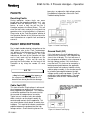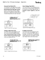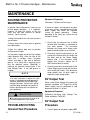
1
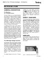
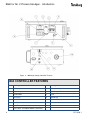
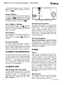
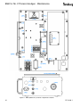
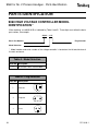
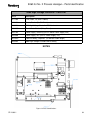
SERVICE MANUAL
CP-13-03.1
MARCH— 2013
9060 HIGH VOLTAGE CONTROLLER
for No. 2 ProcessTM Handgun
(HV2 - Electric Motor)
MODEL: 80102-21X (Electric Motor)
IMPORTANT: Before using this equipment, carefully read
SAFETY PRECAUTIONS, starting on page 1, and all instructions
in this manual. Keep this Service Manual for future reference.
Service Manual Price:
$50.00 (U.S.)
CP-13-03.1
9060 for No. 2 Process Handgun - Contents
CONTENTS
SAFETY:
PAGE
1-6
SAFETY PRECAUTIONS ......................................................................................................... 1
HAZARDS / SAFEGUARDS................................................................................................... 2-5
INTRODUCTION:
7-12
GENERAL DESCRIPTION........................................................................................................ 7
SAFETY FEATURES ................................................................................................................ 7
DISPLAYS ................................................................................................................................ 7
SPECIFICATIONS .................................................................................................................... 8
CONTROLLER FEATURES ...................................................................................................... 9
OPERATOR INTERFACE ....................................................................................................... 10
SWITCHES ............................................................................................................................. 10
LEDS ...................................................................................................................................... 10
BUTTONS .......................................................................................................................... 10-11
CONNECTION INTERFACE ................................................................................................... 11
CONNECTORS....................................................................................................................... 11
FUSES .................................................................................................................................... 11
SIGNAL INTERFACE .............................................................................................................. 12
INSTALLATION:
13-15
GENERAL INFORMATION ..................................................................................................... 13
LOCATION.............................................................................................................................. 13
AC INPUT CONNECTIONS ............................................................................................... 13-14
SAFETY GROUND ................................................................................................................. 14
INPUT VOLTAGE SELECTION .............................................................................................. 14
HIGH VOLTAGE CABLE......................................................................................................... 14
NO. 2 PROCESS HANDGUN TRIGGER SIGNAL .................................................................. 15
OPERATION:
16-20
START-UP .............................................................................................................................. 16
BASIC OPERATIONS ........................................................................................................ 16-17
KV TEST JUMPER ................................................................................................................. 17
SETPOINT OPERATIONS ...................................................................................................... 17
FAULTS .................................................................................................................................. 18
FAULT DESCRIPTIONS .................................................................................................... 18-19
CP-13-03.1
9060 for No. 2 Process Handgun - Contents
CONTENTS
PAGE
MAINTENANCE:
21-32
ROUTINE PREVENTIVE MAINTENANCE .............................................................................. 21
TROUBLESHOOTING ....................................................................................................... 21-22
FAULT TROUBLESHOOTING GUIDE ............................................................................... 23-24
GENERAL TROUBLESHOOTING GUIDE ......................................................................... 25-26
SERVICE LEVEL .................................................................................................................... 27
REPLACEMENT PROCEDURES ...................................................................................... 27-31
PARTS IDENTIFICATION:
33-34
HIGH VOLTAGE CONTROLLER MODEL IDENTIFICATION ................................................. 33
PARTS LIST ........................................................................................................................... 34
ACCESSORIES:
35
ACCESSORIES LIST .............................................................................................................. 35
WARRANTY POLICIES:
36
LIMITED WARRANTY ............................................................................................................ 36
CP-13-03.1
CP-13-03.1
9060 for No. 2 Process Handgun - Safety
SAFETY
SAFETY PRECAUTIONS
Before operating, maintaining or servicing any
Ransburg electrostatic coating system, read
and understand all of the technical and safety
literature for your Ransburg products. This
manual contains information that is important
for you to know and understand. This information relates to USER SAFETY and PREVENTING EQUIPMENT PROBLEMS. To help
you recognize this information, we use the following symbols. Please pay particular attention
to these sections.
A WARNING! states information to alert you
to a situation that might cause serious injury if instructions are not followed.
A CAUTION! states information that tells
how to prevent damage to equipment or
how to avoid a situation that might cause
minor injury.
A NOTE is information relevant to the procedure in progress.
While this manual lists standard specifications
and service procedures, some minor deviations may be found between this literature and
your equipment. Differences in local codes and
plant requirements, material delivery requirements, etc., make such variations inevitable.
Compare this manual with your system installation drawings and appropriate Ransburg
equipment manuals to reconcile such differences.
!
WARNING
The user MUST read and be familiar
with the Safety Section in this manual and
the Ransburg safety literature therein
identified.
This manual MUST be read and thor-
oughly understood by ALL personnel who
operate, clean or maintain this equipment!
Special care should be taken to ensure that
the WARNINGS and safety requirements
for operating and servicing the equipment
are followed. The user should be aware of
and adhere to ALL local building and fire
codes and ordinances as well as NFPA-33
SAFETY STANDARD, prior to installing,
operating, and/or servicing this equipment.
!
WARNING
The hazards shown on the following
page may occur during the normal use of
this equipment. Please read the hazard
chart beginning on page 2.
Careful study and continued use of this manual
will provide a better understanding of the
equipment and process, resulting in more efficient operation, longer trouble-free service and
faster, easier troubleshooting. If you do not
have the manuals and safety literature for your
Ransburg system, contact your local
Ransburg representative or Ransburg.
1
CP-13-03.1
9060 for No. 2 Process Handgun - Safety
AREA
HAZARD
Tells where hazards Tells what the hazard is.
may occur.
Spray Area
Fire Hazard
SAFEGUARDS
Tells how to avoid the hazard.
Fire extinguishing equipment must be present in
the spray area and tested periodically.
Improper or inadequate operation and maintenance proce- Spray areas must be kept clean to prevent the
dures will cause a fire hazard.
accumulation of combustible residues.
Protection against inadvertent
arcing that is capable of causing
fire or explosion is lost if any
safety interlocks are disabled
during operation. Frequent Controller shutdown indicates a
problem in the system requiring
correction.
Smoking must never be allowed in the spray
area.
The high voltage supplied to the atomizer must
be turned off prior to cleaning, flushing or
maintenance.
When using solvents for cleaning:
Those used for equipment flushing should have
flash points equal to or higher than those of the
coating material.
Those solvents used for cleaning must have a
flash point at minimum of 5°C (9°F) greater than
ambient temperature. It is the end users responsibility to ensure this condition is met.
Spray booth ventilation must be kept at the rates
required by NFPA-33, OSHA, and local codes.
In addition, ventilation must be maintained
during cleaning operations using flammable or
combustible solvents.
Electrostatic arcing must be prevented.
Test only in areas free of combustible material.
Testing may require high voltage to be on, but
only as instructed.
Non-factory replacement parts or unauthorized equipment modifications may cause fire or
injury.
If used, the key switch bypass is intended for
use only during setup operations. Production
should never be done with safety interlocks disabled.
Never use equipment intended for use in waterborne installations to spray solvent based materials.
The paint process and equipment should be set
up and operated in accordance with NFPA-33,
NEC, and European Health and Safety Norms.
CP-13-03.1
2
9060 for No. 2 Process Handgun - Safety
AREA
HAZARD
SAFEGUARDS
Tells where hazards
may occur.
Tells what the hazard is.
Tells how to avoid the hazard.
Spray Area
Fire and/or explosion.
Electrostatic arcing MUST be prevented.
The 78789 control panel, LEPS5001 power supply and all other electrical equipment must be
located outside Class I or II, Division 1 or 2 hazardous areas, in accordance with NFPA-33.
Test only in areas free of flammable or combustible materials.
The current overload sensitivity MUST be set as
described in the OVERLOAD ADJUSTMENT
Procedures section of this manual. Protection
against inadvertent arcing that is capable
of causing fire or explosion is lost if the current overload sensitivity is not properly
set. Frequent power supply shutdown indicates
a problem in the system which requires correction.
Always turn the control panel off prior to flushing, cleaning, or working on spray system equipment.
Ensure that the control panel is interlocked with
the ventilation system and conveyor in accordance with NFPA-33, EN 50176.
Have fire extinguishing equipment readily available and tested periodically.
General Use and
Maintenance
Improper operation or mainte- Personnel must be given training in accordance
nance may create a hazard.
with the requirements of NFPA-33, EN 60079-0.
Personnel must be properly Instructions and safety precautions must be
trained in the use of this equip- read and understood prior to using this equipment.
ment.
Comply with appropriate local, state, and national codes governing ventilation, fire protection,
operation maintenance, and housekeeping. Reference OSHA, NFPA-33, EN Norms and your
insurance company requirements.
3
CP-13-03.1
9060 for No. 2 Process Handgun - Safety
AREA
HAZARD
Tells where hazards Tells what the hazard is.
may occur.
Electrical
Equipment
High voltage equipment is utilized.
Arcing in areas of flammable or
combustible materials may occur.
Personnel are exposed to high
voltage during operation and
maintenance.
SAFEGUARDS
Tells how to avoid the hazard.
The power supply, optional remote control
cabinet, and all other electrical equipment
must be located outside Class I or II, Division
1 and 2 hazardous areas. Refer to NFPA-33
or EN 50176.
Turn the power supply OFF before working on
Protection against inadvertent arcthe equipment.
ing that may cause a fire or explosion is lost if safety circuits are disTest only in areas free of flammable or comabled during operation.
bustible material.
Frequent power supply shut-down
indicates a problem in the system Testing may require high voltage to be on, but
only as instructed.
which requires correction.
An electrical arc can ignite coating Production should never be done with the
materials and cause a fire or explo- safety circuits disabled.
sion.
Before turning the high voltage on, make sure
no objects are within the sparking distance.
Toxic Substances
Certain material may be harmful if Follow the requirements of the Material Safeinhaled, or if there is contact with ty Data Sheet supplied by coating material
the skin.
manufacturer.
Adequate exhaust must be provided to keep
the air free of accumulations of toxic materials.
Use a mask or respirator whenever there is a
chance of inhaling sprayed materials. The
mask must be compatible with the material
being sprayed and its concentration. Equipment must be as prescribed by an industrial
hygienist or safety expert, and be NIOSH approved.
CP-13-03.1
4
9060 for No. 2 Process Handgun - Safety
AREA
HAZARD
SAFEGUARDS
Tells where hazards Tells what the hazard is. Tells how to avoid the hazard.
may occur.
Spray Area /
High Voltage
Equipment
There is a high voltage
device that can induce an
electrical charge on ungrounded objects which
is capable of igniting coating materials.
Parts being sprayed must be supported on conveyors
or hangers and be grounded. The resistance between
the part and ground must not exceed 1 megaohm.
(Reference NFPA-33 or EN 50176)
All electrically conductive objects in the spray area,
with the exception of those objects required by the
Inadequate grounding will process to be at high voltage, must be grounded.
cause a spark hazard. A
spark can ignite many Any person working in the spray area must be
coating materials and grounded.
cause a fire or explosion.
Unless specifically approved for use in hazardous locations, the power supply and other electrical control
equipment must not be used in Class 1, Division 1 or
2 locations or Class 1, Zone 0 for European Applications.
5
CP-13-03.1
9060 for No. 2 Process Handgun - Safety
NOTES
CP-13-03.1
6
9060 for No. 2 Process Handgun - Introduction
INTRODUCTION
GENERAL DESCRIPTION
The Ransburg
No. 2 Handgun Process
The No. 2 ProcessTM is an electrical atomization method for applying coatings to objects
electrostatically. The No. 2 Process Handgun
system applies a high voltage, negative, DC
charge to the applicator bell, creating an
electrostatic field between the bell and the
target object. The target is electrically grounded through its support which may be stationary or moving; or through an electrical connection to a known true earth ground.
A regulated pressure fluid system delivers
coating material to the bell when the gun is
triggered. There, the fluid travels across the
face of the rotating bell and becomes charged.
The fluid is electrically atomized at the edge of
the bell forming a fine mist which, under the
influence of the electrostatic field, is attracted
to and deposited on the target object. The
forces between the charged particles and the
grounded target are sufficient to turn almost
all overspray around and deposit it on the side
and back surfaces of the target. Thus, a high
percentage of the spray is deposited on the
target and overspray is controlled.
The 9060 High Voltage Controller
Handgun has a fixed setpoint value which
can NOT be adjusted. The triggering of the
HV is initiated by the on-off switch on the
No. 2 Process Handgun. For more information, please refer to the “Theory of
Operation” in the “Operation” section of this
manual.
SAFETY FEATURES
The Ransburg 9060 High Voltage Controller
provides maximized operational safety. The
protections include detection of Ground
Faults, Cable Faults, Feedback Signal Fault,
Current Limit Fault and Overvoltage Fault.
The microprocessor circuits provide a
controlled output load curve, which limits the
high voltage output to safe levels while
monitoring control and feedback signals for
unsafe conditions. Maximum operational
safety is obtained when the correct applicator settings are used and when safe distances between the applicator and target are
observed and followed.
The maximum
efficiency of the high voltage controller is
based on load.
DISPLAYS
The front panel displays the high voltage set
point as well as a reading of the gun current
output. The gun current is derived from
feedback signals between the controller and
the cascade.
The Ransburg 9060 High Voltage Controller
(80102-21X) is used to provide high voltage
for the No. 2 Process Handgun. It uses a
combination of proven high voltage generation
technology and microprocessor-based control.
It uses current feedback information to maintain the required kV output for the No. 2
Process Handgun. The processor circuitry
provides the maximum in applicator transfer
efficiency, while maintaining the maximum
safety.
The 9060 Controller for the No. 2 Process
7
Figure 1: 9060 High Voltage Controller (HV2)
CP-13-03.1
9060 for No. 2 Process Handgun - Introduction
SPECIFICATIONS
NOTE
The 9060 High Voltage Controller is
factory supplied with a latch (#E5-1-065091) that can be opened using the supplied key (#E3-2).
The 9060 High Voltage Controller is available as follows:
9060 Part Used with No. 2 Gun
No.
Type
Gun No.
80102-211
Electric Motor, Domestic
19372-XX
80102-212
Electric Motor, European
19372-XX
80102-213
Electric Motor, China
19372-XX
Environmental
Operating Temperature:
Storage and Shipping
Temperature:
Humidity:
0°C to +40°C
-40°C to +85°C
95% Non-Condensing
Physical
Height:
16.5 cm (6.5 inches)
Width:
37.8 cm (14.9 inches)
Depth:
30.7 cm (12.1 inches)
10.2 kg (22.5 lbs.)
Weight:
Electrical
Input:
Voltage:
Current:
Frequency:
Wattage:
100-240 VAC
1 A max. RMS
50/60 Hertz
40 watts (max.)
Voltage:
100 kV (80102-21X)
Current:
115 Microamps Max.
Output:
CP-13-03.1
8
9060 for No. 2 Process Handgun - Introduction
Figure 2: 9060 High Voltage Controller Features
9060 CONTROLLER FEATURES
9
No.
Description
No.
Description
1
kV Display
9
kV Setpoint/Adjust Buttons (reference)
2
High Voltage On Indicator
10
High Voltage Cable Connector
3
Reset Button
11
Fuses
4
µA Display
12
Ground Lug
5
Fault Indicator
13
AC Inlet Receptacle
6
On-Off Switch
7
Local/Remote Mode Indicator (reference)
8
“One Touch” kV Setpoint Buttons (reference)
CP-13-03.1
9060 for No. 2 Process Handgun - Introduction
OPERATOR INTERFACE
please refer the Fault Descriptions section in
the Operations portion of this manual.
The 9060 Controller shown in Figure 3, has a
simple operator interface consisting of 7 LEDs
(Light Emitting Diodes), one (1) power switch,
seven (7) buttons, one (1) current LED bargraph, and two (2) screens containing sevensegment displays. The following describes the
behavior of the interface components used with
the No. 2 Process Handgun.
Local Mode LED Indicator
The local mode LED indicator is a left pointing
triangle and is located on the left side the HV
control button on the center of the operator
interface. This LED is lit when the Controller is
used with the No. 2 Process Handgun.
Remote Mode LED Indicator
The remote mode LED indicator should NOT be
lit for No. 2 Process Handgun units.
Active Preset LED Indicators (3)
Figure 3: 9060 Operator Interface
SWITCHES
Power Switch
The active preset LED indicators are located
directly above each of the Preset Buttons. The
No. 2 Process Handgun (80102-21X) is designed to operate at only one specific setpoint,
therefore these LEDs only indicate which of the
3 buttons was the last button pressed and have
no affect on the setpoint for the No. 2 Handgun.
BUTTONS
LEDs
The seven buttons on the operator interface are
normally used to adjust the KV preset, access
submenus, view operating hours and reset
overloads and faults. The No. 2 Process
Handgun only uses a subset of the 9060 High
Voltage Controllers functionality and the
following lists the behavior for each button
when the unit is configured for the No. 2
Process Handgun.
High Voltage On Indicator
Preset 1 Button
The 9060 Controller contains a single rocker
switch for power On/Off selection. When the
unit is powered on, the screens should be lit
and display the gun display type information
and the software version number for a short
period of time.
The red High Voltage On Indicator is lit when a
trigger signal has been received by the unit and
the high voltage output from the cascade has
been enabled.
Fault Indicator
The red Fault Indicator is lit when a fault occurs
as determined by the microprocessor. When a
fault occurs the light will turn on and the identification code for the fault will be displayed,
blinking, on the µA meter display. For more
information on the faults and fault ID codes,
CP-13-03.1
The Preset 1 Button (on the left just below the
kV display) if pressed with the reset button at
the same time, the screen will display the
resettable High Voltage ON operating hours for
3 seconds on the display screens. The preset
1 button will NOT affect the setpoint of the No. 2
Process Handgun.
Preset 2 Button
The Preset 2 Button (in the center below the kV
display) if pressed with the reset button at the
same time, the screen will display the nonresettable High Voltage ON operating hours for
10
9060 for No. 2 Process Handgun - Introduction
3 seconds on the display screens. The preset 2
button will NOT affect the setpoint of the No. 2
Process Handgun.
Preset 3 Button
The Preset 3 Button (on the right side below the
kV display) has NO functionality when the 9060
is configured for used with the No. 2 Process
Handgun. The preset 3 button will NOT affect
the setpoint of the No. 2 Process Handgun.
Left (-)/Right (+) Buttons
The left(-)/right(+) buttons have NO functional
behavior when the 9060 is configured for use
with the No. 2 Process Handgun and CAN NOT
modify the setpoint.
Reset Button
The reset button is used to clear fault or overload conditions. This will NOT prevent any
other active fault conditions from triggering a
new fault.
HV Control Button
This button, shown in the center of Figure 3,
has no currently defined behavior. The unit is
placed in LOCAL mode at power-on and should
remain in LOCAL mode while the unit is configured for use with the No. 2 Process Handgun.
CONNECTION INTERFACE
The 9060 Controller connection interface shown
in Figure 4, provides all of the required connections for setting up a No. 2 Process Handgun
(80102-21X). This connection interface consists of one (1) high voltage cable connector,
one (1) ground lug connection, two (2) fuses,
and one (1) AC inlet receptacle.
CONNECTORS
High Voltage Cable Connector
The high voltage cable connector is the largest
connector and is located on the far right of the
connection interface. This connector is designed for use with the superflex high voltage
cable 19370 that connects with the No. 2
Process Handgun.
11
Figure 4: 9060 Connection Interface
Ground Lug Connection
The ground lug connection is located directly
below the fuses and has a ground logo sticker
directly below it. This lug is provided as an
external ground connection point used to
ground the 9060 to an earth ground via a
ground cable. This ground lug connection can
also be used as the ground point for the high
voltage cable ground.
AC Inlet Receptacle
The AC inlet receptacle is a standard IEC C14
Appliance Inlet connector with a maximum
rating of 250 VAC. It can handle both 115VAC
and 230 VAC inputs at 50 or 60 Hz. The unit is
shipped with the appropriate rated AC cord for
the particular installation.
FUSES
Fuses
There are two (2) time delay fuses (250V, 1A,
5mm x 20mm) installed in fuse holders on the
connection interface. They are located directly
above the ground lug connection. They are
present to provide a measure of safety against
power surges through the AC input. The top
fuse holder is connected in series between the
HOT line (L) input connection and the Interlock
AC line connection terminal 1TB-L2.
The
bottom fuse holder is connected in series
between the neutral AC input connection and
the neutral input connection of the AC line
power filter.
Spare Fuses
The Controller also comes with two (2) spare
fuses (250V, 1A, 5mm x 20mm) mounted in
holders, inside the lid of the Controller.
CP-13-03.1
9060 for No. 2 Process Handgun - Introduction
SIGNAL INTERFACE
The 9060 Controller, when configured for use
with the No. 2 Process Handgun, requires only
one signal input for operation, the trigger signal.
The trigger signal input (J3-5) is controlled from
a signal output from the relay board. This
output is activated when the No. 2 Process
Handgun’s on-off switch is turn on.
CP-13-03.1
12
9060 for No. 2 Process Handgun - Installation
INSTALLATION
GENERAL INFORMATION
LOCATION OF THE 9060
The following section contains general information on the installation of 9060 High Voltage
Controller.
Install the Controller in an area must be 6.1m
(20’) from where the spray target is located
in accordance with federal, state, and local
codes. The area should protect the Controller
from the possibility of environmental intrusion
(such as dust or moisture), have ambient
temperatures that do not exceed 40°C, and be
as close to the applicator as possible to minimize the length of the high voltage cable.
!
WARNING
The 9060 Controller MUST be located a
minimum of 6.1m (20’) outside or away
from the target being sprayed.
The User MUST read and be familiar
This manual MUST be read and thor-
oughly understood by ALL personnel who
operate, clean, or maintain this equipment!
Special care should be taken to ensure that
the warnings and requirements of operating
and servicing safely are followed. The user
should be aware of and adhere to ALL local
building and fire codes and ordinances as
well as NFPA-33, OSHA, and all related
country safety codes prior to installing, operating, and/or servicing this equipment.
Only approved applicators should be
used with the 9060 High Voltage Controller.
NOTE
As each installation is unique, this information is intended to provide general installation information for the 9060 Controller. Consult your authorized Ransburg
distributor for specific directions pertaining
to the installation of your equipment.
DO NOT locate the Controller near or
adjacent to heat producing equipment
such as ovens, high wattage lamps, etc.
AC INPUT CONNECTIONS
For non-conduit installations, plug the detachable AC line cord into the receptacle on the side
of the 9060 Controller. Plug the other end of
the line cord into a properly grounded 120 volt
AC outlet.
For those few installations where it is required
to run the AC input wiring in conduit, perform
the following:
1. Ensure the AC line cord is unplugged
and remove the AC inlet receptacle wiring
from TB1-N, TB1-L1 and TB1-EARTH
GROUND (See Figures 5).
2. Remove the mounting hardware from the
AC inlet receptacle and remove it from the
side of Controller.
3. Install the Conduit Adapter Plate (supplied)
in the hole where the AC inlet receptacle
was removed (see Figure 6).
4. Install
13
CAUTION
!
with the “Safety” section of this manual.
the
AC
input
wiring
(0.8mm2
CP-13-03.1
9060 for No. 2 Process Handgun - Installation
(18AWG) minimum) through the Conduit
Adapter Plate using conduit and wire to TB1
as follows:
Hot/Line
to TB1-L1
!
CAUTION
The ground wire assembly MUST be
connected from the Controller ground
stud to a true earth ground.
Neutral/Common to TB1-N
Ground
to TB1-EARTH GROUND
INPUT VOLTAGE
SELECTION
The 9060 Controller accepts universal input
voltage between 100 and 240 VAC at 50 or 60
Hz. There is no need to change any switch
settings when changing input from 110 to 240
VAC or from 240 to 110 VAC.
NOTE
Figure 5: Location of TB1 & TB2 in Controller
All 9060 units (80102-21X) shipped
from the factory for either 110 VAC input
or 240 VAC input will have a 72771-06, 1
Amp front panel fuses installed.
HIGH VOLTAGE CABLE
Figure 6: Installation of Conduit Adapter Plate
SAFETY GROUND
Crimp the appropriate connector onto the
ground wire assembly and install from the
Controller ground stud, located on the side
panel, to a true earth ground.
Position the No. 2 Process Handgun in the
spray area and route the high voltage cable to
the Controller. The cable should be routed so
that it is not damaged by foot and vehicle traffic
and also so that is not close to areas of high
temperature (129°F+). The operator should
have free movement of the applicator and all
bend radii of the cable should not be less than 6
-inches (15 cm). Connect the high voltage
cable to the Controller and tighten the retaining
nut and set screw. If during the routing of the
high voltage cable it is required to remove it
from the No. 2 Handgun, care should be taken
when reinstalling so that the high voltage cable
is completely engaged.
!
WARNING
The Controller MUST be OFF when the
No. 2 Handgun is removed or reinstalled.
CP-13-03.1
14
9060 for No. 2 Process Handgun - Installation
NO. 2 PROCESS HANDGUN TRIGGER SIGNAL
NOTES
The No. 2 Process Handgun (80102-21X) uses
a relay board (P/N 76649-00) to provide the
trigger signal output. The listed relay board is
mounted on the top of the cascade casing
inside the 9060 Controller chassis. When the
No. 2 Process Handgun on-off switch is turned
on, it activates the relay on the board which
connects the trigger input (J3-5) to ground.
This signal causes the PC mainboard to turn on
the high voltage.
For information on the
replacement and wiring of a relay board, see
the “Replacement Procedures” in the Maintenance Section of this Manual.
15
CP-13-03.1
9060 for No. 2 Process Handgun - Operation
OPERATION
START-UP
!
After all installation procedures are completed,
operation of the applicator may begin. When
the ON-OFF switch is turned on, the kV display
will show the applicator type the 9060 Controller
is configured for and the µA (microamp) display
will show the current software revision level as
shown in Figure 7. These items are displayed
for approximately 10 seconds.
WARNING
USE ONLY the gun type configuration
for the No. 2 Process Handgun (8010221X). Using the wrong configuration may
allow for operation outside the recommended parameters and values for the
applicator and can result in damage or un
-safe operation.
After the initial start-up delay, the unit will be
configured for the applicator based on the gun
type jumper settings and is ready for standard
operation.
BASIC OPERATIONS
The basic operations are general operations
that are available.
Triggering High Voltage
Figure 7: Controller Start-Up Display
The controller comes preconfigured for the No.
2 Process Handgun from the factory. The
following table lists the display value and
jumper settings for the unit. This table is a
reference to verify that the gun configuration
jumpers are in their correct positions if unexpected behavior is observed.
START-UP DISPLAY
Type
Description
Jumpers
No. 2 Process Handgun
99
High voltage is actuated by the presence of an
active trigger signal. This is accomplished by
turning the on-off switch of the No. 2 Process
Handgun to the “on” position. The kV is displayed on the kV display, the actual current
draw on the µA display, and the high voltage
light illuminates. Under the µA display is a bar
graph meter that illuminates according to the
actual current draw shown in Figure 8.The
green and yellow regions of the bar graphs
meter indicate output current is in the optimum
range for maximum transfer efficiency. The red
region of the bar graph indicates high output
current causing decreased transfer efficiency.
If high output, check maintenance of applicator
and external equipment of the power supply.
13
(Electric Motor)
CP-13-03.1
16
9060 for No. 2 Process Handgun - Installation
board. By covering (shorting) both terminals of
this jumper, the high voltage of the spray
applicator can be activated. Thus, for testing
and troubleshooting, high voltage output can be
obtained without the need to trigger air through
the spray applicator. After testing, the jumper
must be repositioned so that it covers only
one terminal (open) or the high voltage will
stay on all the time. See Figure 10 for the
location of KV test jumper J8.
Figure 8: µA Bar Graph Meter Display
Measuring “High Voltage On”
Time
The 9060 High Voltage Controller records the
amount of time the high voltage is triggered on
up to 99,999 hours. This value is display on the
kV and µA displays of the unit. There are two
registers that retain this information, one that
may be reset, the other that is permanently
retained in memory. The number of hours the
unit’s high voltage has been on may be displayed by depressing at the same time the
preset 1 and reset buttons (See Figure 9). The
display will show hours of use for 3 seconds.
This is the resettable register.
To reset this register, press the reset button
while the hours are displayed.
To view the non-resettable register, press the
preset 2 and reset buttons at the same time.
This display will show the hours for 3 seconds.
Figure 10: KV Test Jumper Location
!
WARNING
If jumper J8 is left covering (shorting)
both terminals, high voltage will be on
whenever the AC power is turned on.
NOTE
Use Ransburg Calibrated Equipment
ONLY for testing and troubleshooting. Refer to the “Parts” section of this manual for
part numbers for testing equipment.
SETPOINT OPERATIONS
Voltage Setpoint
Figure 9: Display “High Voltage On” Time
KV TEST JUMPER
To assist in testing and troubleshooting, a
jumper (J8) has been added to the main PC
17
The voltage on the 9060 High Voltage Controller, when configured for use with the No. 2
Process Handgun (80102-21X), is NOT adjustable. The Electric Motor No. 2 Handgun is
designed to operate at only a set point of
100kV. The display will always show 99kV.
CP-13-03.1
9060 for No. 2 Process Handgun - Operation
loose pins, or replace the high voltage section.
For additional information, refer to the Fault
Troubleshooting Section.
FAULTS
Resetting Faults
During operation, various faults can occur
based upon the operating conditions or if any
problems with the 9060 unit arise. If a fault
occurs, to reset a fault, turn off the No. 2
Handgun and press the Reset Button . This will
clear the fault status and put the unit back into
operation unless a fault condition is still present.
Please refer to the “Fault Description” portion of
the Operation Section of this Service manual for
more information on a specific fault and how to
correct it.
FAULT DESCRIPTIONS
Figure 11: Cable Fault Display
For in depth troubleshooting information on the
9060, please refer to the “Fault Troubleshooting” portion of the Maintenance Section of this
service manual. If a fault occurs, the Fault
Indicator on the front of the Controller will light
and a fault code will be displayed on the
microamp display. Faults can be reset by
pressing the Reset button on the front of the
Controller or by using the remote I/O reset
signal.
NOTE
Any fault code not listed that appear on
the screen are a likely indication of a PC
board failure due to possible arc damage.
Ground Fault (GF)
If this fault occurs, the fault indicator on the
control unit will illuminate, a GF indication will
show in the uA display. This fault will occur if
the microprocessor detects a loss of ground at
the high voltage section. If this fault occurs,
reset the fault. This fault can be caused by a
broken ground path between the applicator
and the control unit and may indicate a faulty
cable or plug assembly. It can also be caused
by a broken ground path between the high
voltage section and the pc board. Check the
wiring to the high voltage section. For more
information, refer to Fault Troubleshooting
Section.
Cable Fault (CF)
This fault will occur if high voltage is active and
the microprocessor detects that no current is
being supplied to the applicator. This indicates
a connection problem from the control unit to
the cascade or handgun barrel assembly.
Typical causes include a faulty low voltage
cable, stuck pins on the plug assembly, or
contaminated contacts on the applicator. This
may also indicate a faulty barrel assembly for a
handgun. This could also indicate a connection
problem between the pc board and the high
voltage section. Check the wiring harness for
CP-13-03.1
Figure 12: Ground Fault Display
18
9060 for No. 2 Process Handgun - Operation
Current Limit Fault (CL)
Over Voltage Fault (OU)
This fault occurs if the output current exceeds
the maximum current by 20µA. This fault can
be caused by excessive overspray on the applicator or a paint formulation that is too conductive. It may also be caused by a bad pc
board. Clean the applicator, check the paint
formulation, or replace the pc board. See Fault
Troubleshooting Section for more information.
This fault will occur if the microprocessor detects the unit is trying to output voltage above
the required for the specific applicator type. If
this occurs, reset the Controller. If this fault
continues to occur, replace the main PC
board.
Figure 13: Current Limit Fault Display
Voltage Cable Fault (UC)
This fault will occur if the microprocessor detects a loss of the voltage feedback signal.
This can be caused by a failed high voltage
cable, a failed high voltage section, or a failed
pc board. Replace the high voltage cable and
re-test. If still faulty, replace the high voltage
section or pc board and re-test.
Figure 14: Voltage Cable Fault Display
19
Figure 15: Over Voltage Fault Display
Feedback Fault (FF)
This fault will occur if the microprocessor detects a loss of the current feedback signal. If
this occurs, reset the fault. If this fault occurs
repeatedly, refer to the Fault Troubleshooting
Section to determine if the problem is with the
high voltage section or the main pc board.
Figure 16: Current Limit Fault Display
CP-13-03.1
9060 for No. 2 Process Handgun - Operation
NOTES
CP-13-03.1
20
9060 for No. 2 Process Handgun - Maintenance
MAINTENANCE
ROUTINE PREVENTIVE
MAINTENANCE
Equipment Required:
In general, little maintenance is necessary to
ensure proper operation. It is important,
however, to keep the interior of the unit
clean and free from moisture or foreign
material. For this reason:
If shocks or sparks are noticed at any point
in the spray system, immediately turn off the
power supply and check the complete
system for proper grounding.
Proper
grounding of the spray gun system can be
verified as follows:
1.Keep the exterior of the unit free from dust
accumulation.
2.Always clean the exterior prior to opening
the cabinet door.
3.Open the cabinet door only to perform
maintenance or repair.
4.If the power supply end of the high voltage
cable becomes dirty, clean the end of the
cable with a suitable, clean, non-polar
solvent and apply a light coat of dielectric
grease. On a yearly basis, check to ensure
that the dielectric grease (70863-00) is
covering the electrical contact point in the
High Voltage Tube. If not, add grease as
needed.
NOTE
As each installation is unique, this information is intended to provide general installation information for the 9060 High
Voltage Controller. Consult your authorized Ransburg distributor for specific directions pertaining to the installation of
your equipment.
Ohmmeter—To Measure Resistance
1. Ensure that the clamp of the 14 AWG
Ground Wire Assembly is connected to
true earth ground.
The resistance
between the clamp and a known earth
ground should read less than 10 ohms.
2. Place one end of the ohmmeter on the
clamp of the Ground Wire Assembly and
the other end on the Power Supply
ground stud. If the ohmmeter reads
greater than 10 ohms, replace the 14
AWG Ground Wire Assembly.
3. Connect one end of the ohmmeter to the
Power Supply ground stud and the other
to the metal gun handle. If the ohmmeter
reads greater than 10 ohms repair or
replace the high voltage cable.
KV Output Test
When a lack of high voltage at the spray gun
indicates a problem, a kV Output Test of the
Power Supply may be performed to help
determine whether it is at fault.
Equipment Required:
!
CAUTION
Do not immerse any part of, or all of an
assembled applicator in any liquid.
21
Calibrated Ransburg High Voltage Test
Probe and Meter (76652-01)
TROUBLESHOOTING
KV Output Test
Procedure
Ground Test Procedure
1. Turn AC power to the power supply OFF.
CP-13-03.1
9060 for No. 2 Process Handgun - Maintenance
2. Remove the high voltage (HV) cable from
the power supply.
!
WARNING
Whenever removing high voltage cables
from equipment, ground the plug end of
the cable(s) by contacting the plug to electrical ground. DO NOT touch the plug until
it has been grounded. This will eliminate
the possibility of residual charge causing
electrical shock.
3. Open the cabinet door and position
jumper J8, shown in Figure 11, on the
main PC Board so that it covers (shorts)
both terminals.
4. Attach the appropriate HV cable to the
Test Probe (76652-01), properly ground
the probe to a true earth ground and turn
the Test Probe Meter on (see Operation
Manual of 76652-01 Tester).
5. Insert the Test Probe HV cable into the
Power Supply HV Tube until it bottoms
out.
6. Turn the power supply ON.
7. Read the output voltage displayed on the
8. Disconnect the Test Probe (76652-01)
and reposition jumper J8 so that it covers
only one terminal.
When ready to
resume spray operations, reconnect the
spray gun HV cable and turn the power
supply on.
Bench Testing
Equipment Required:
Volt/Ohmmeter
The “Troubleshooting Guide” provides
information for troubleshooting the power
supply when improper operation is obtained
and the problem has been traced to the
power supply.
Proper troubleshooting
should ONLY be accomplished with specific
test equipment by qualified electronics
technicians or authorized Ransburg representatives.
Before troubleshooting, ensure that the
power supply is plugged into a live outlet of
appropriate voltage. All electrical measurements in the “Troubleshooting Guide” are
nominal and may vary as much as ±10%
depending on the test conditions and the test
equipment used. Refer to Figure 17 for
location of parts called out in the
“Troubleshooting Guide”.
NOTE
Ensure that the Test Probe HV cable
makes good contact both inside the Test
Probe and inside the Power Supply HV
Tube.
meter, then turn the power supply OFF.
If the voltage DOES READ correctly (see
“Specifications” in the “Introduction”
section of this manual), the problem is
not in the Power Supply, therefore the HV
Cable and spray gun should be checked
for the cause. If the voltage DOES NOT
READ correctly, the problem is with the
power
supply.
Consult
the
“Troubleshooting Guide” to locate the
specific problem.
CP-13-03.1
For bench testing, jumper J8 should be used
to trigger the high voltage output (see “KV
Test Jumper” previously discussed in this
section).
Diagnostic LED’s
There are two diagnostic LED’s located on
the relay board. LED1 is a green LED that
indicates 24 VDC input is being received
from power supply 2PS. LED1 should be lit
whenever the power supply ON/OFF switch
is ON. LED2 is a red LED that indicates 24
VDC is being output to the gun motor. LED2
should be lit whenever the toggle switch at
the back of the gun is turned ON.
22
9060 for No. 2 Process Handgun - Maintenance
FAULT TROUBLESHOOTING GUIDE
!
WARNING
Before troubleshooting gun and control unit problems, flush the gun with solvent and purge
with air. Some of the tests will require high voltage to be applied to the gun, so the gun must
be empty of paint and solvent.
Fault
Description
Solution
Cable Fault (CF)
The Cable Fault indicates the con- 1. Check for loose wiring between the pc
trol unit does not detect a high
board connector and the high voltage secvoltage section on the end of the
tion by pulling on each wire. Repair if necessary. Insure both connectors are secure
cable. The fault typically occurs at
and re-test for CF fault.
a high voltage trigger.
2. Replace high voltage section or send unit
in for repair.
3. Send unit in for repair.
Ground Fault (GF)
The Ground Fault is typically
caused by a ground connection
problem, and can create a safety
hazard. It can occur without high
voltage and will not reset.
1. Check for loose wiring between the pc
board connector and the high voltage section by pulling on each wire. Repair if necessary. Insure both connectors are secure
and re-test for GF fault.
2. Adjust the setpoint to 20kV and turn on the
high voltage. A GF fault indicates a faulty
pc board - replace.
3. Replace high voltage section or send unit
in for repair.
4. Send unit in for repair.
Over-Voltage Fault The Over Voltage Fault indicates
the output voltage exceeds the
(OU)
design specifications. It typically
occurs during a high voltage trigger.
23
1. Check connections using two finger pull
test to ensure they are connected.
2. Replace the pc board.
CP-13-03.1
9060 for No. 2 Process Handgun - Maintenance
Fault
Description
Solution
1. This may indicate the paint conductivity is too high
(resistance too low) or the outside of the applicator
is contaminated with paint.
ed the overload threshold. This
fault is only active if jumper 17
is shorted. The overload
threshold is normally set at 10
µA below the maximum output
of the applicator.
Over-Load Fault The Over Load Fault indicates
the current output has exceed(OL)
Current Limit
Fault (CL)
Feedback Fault
(FF)
The Current Limit Fault indicates the current output of the
gun has exceeded the maximum allowable output current.
It typically occurs with the high
voltage on.
1. Clean outside of the applicator.
2. Replace barrel or applicator.
3. Send applicator in for repair.
The Feedback Fault indicates
1. Securely attach a ground wire to the applicator electhere is no current feedback or
trode.
it is incorrect. It typically occurs
2. Set the high voltage to maximum and short the KV
with the high voltage on.
test jumper.
3. The current reading on the control unit should rise
up to the maximum current output. If it does not,
send the applicator in for repair.
Voltage Cable
Fault (UC)
The Voltage Feedback Fault
indicates the cascade drive signal is not present. It typically
occurs when high voltage is
triggered.
1. Turn off the voltage controller and remove the high
voltage cable from the voltage controller.
2. Turn on the power and place a jumper across the
KV Test Jumper. If the fault occurs, send the voltage controller in for repair. If no fault occurs, continue.
3. Either the high voltage cable or if using a hand gun,
the gun resistor tube has failed.. If available, replace the high voltage cable, or continue to test the
resistor tube.
4. To test the resistor tube, remove the resistor tube
from the gun and inspect for signs of burning or arcing. Cracks or black marks indicate failure of the
resistor tube, indicating the resistor tube must be
replaced. Measure the resistance using a tri-meter
connected to the black end of the tube and screwdriver in the other end. The measurement must be
150 to 170 Mega ohms. Replace resistor tube if the
reading is not correct.
5. Replace high voltage cable or send applicator unit in
for repair.
CP-13-03.1
24
9060 for No. 2 Process Handgun - Maintenance
GENERAL TROUBLESHOOTING GUIDE
General Problem
Possible Cause
Black Display when from 1. No AC power present
panel switch is turned to 2. Blown or Defective Fuse
the “ON” position.
3. Connector 7PL not properly
plugged into main PC board
Solution
1. Ensure voltage across terminals L1
and N of terminal block 1TB is between 90 and 264 VAC.
2. Replace blown/defective fuse
4. Improper input line voltage
3. Properly attach connector.
5. Defective ON/OFF switch
1SW
4. Verify connection to the voltage
across terminals L2 and N of 1TB is
between 90 and 264 VAC.
6. Defective power supply 1PS
5. Voltage across terminals 1A and 2A of
ON/OFF switch 1SW should be between 90 and 264 VAC. If not, replace switch 1SW.
6. Voltage across terminals 2 and 3 of
plug 7PL on main PC board should be
24 VDC. If not, replace power supply
1PS.
Motor Rotating, But No
Or Low kV Output At
Spray Gun
1. The connector J3 on the PC 1. Properly attach connector J3-5. Verify
Mainboard or the connections
that trigger input line is connected into
on the relay board connector
the 5th position from bottom of case.
4PL may not be properly atVerify continuity between 4PL-6 and
tached to their respective
J3-5 connector positions. Verify contilocations.
nuity between 4PL-7 and ground lug.
2. Defective spray gun or high
voltage cable.
2. Perform a Current Output Test on the
power supply. If proper readings are
3. Loose or broken wire in power supply.
obtained, check cable or spray gun for
cause. (See Spray Gun’s Service
4. Main PC board defective.
Manual.)
5. Defective high voltage multiplier.
3. Check all wiring connections for integrity. Repair wiring as needed.
4. If spare board present, replace board
or Send unit in for repair.
5. Send unit in for repair.
25
CP-13-03.1
9060 for No. 2 Process Handgun - Maintenance
General Problem
Possible Cause
Motor Not Rotating And
No kV Output At Spray
Gun, LED1 Off
1. Improper or No input line volt- 1. Ensure voltage across terminals 1 and
age at 6PL
3 of connector 6PL is between 90 and
264 VAC.
2. Defective 24 VDC power supply 2PS
2. Voltage across terminals 1 and 6 of
plug 6PL of power supply 2PS should
be 24VDC. If not, replace power supply 2PS.
Motor Rotating And No 1. Defective control wires in cable or switch in gun
kV Output At Spray Gun,
2. Defective relay board
LED1 On
Solution
1. Check for continuity from 4PL-3 of
relay board to gun handle when
switch at gun is ON. If no continuity,
replace high voltage cable or gun ON/
OFF switch.
2. If #1 above checks ok, replace relay
board.
Motor Not Rotating But 1. Defective relay board fuse F4 1. Replace defective fuse.
kV Output Ok, LED2 Off
Motor Not Rotating But 1. Defective control wires in
high voltage cable
kV Output Ok, LED2 On
1. Replace high voltage cable.
Motor Rotating Too Fast 1. Defective power supply 2PS
1. Voltage across terminals 1 and 6 of
plug 6PL of power supply 2PS should
be 24VDC. If not, replace power supply 2PS.
Excessive Current Draw 1. Short in cable or gun
1. Remove cable from power supply. If
problem goes away, check gun or cable for cause.
2. Defective main PC board
3. Defective high voltage multiplier
2. Test PC board with LTST5000 Tester.
Replace PC board if improper results
are obtained.
3. If 1 and 2 above are okay, replace
high voltage multiplier.
Excessive Shocking
CP-13-03.1
1. Discontinuity in ground circuit 1. Perform the Ground Test Procedure
as describe in the “Maintenance” section of this manual.
26
9060 for No. 2 Process Handgun - Maintenance
SERVICE LEVEL
Personnel who service this unit must be
qualified electronics technicians. Replacement parts are designed to be made at the
assembly level. See “Parts Identification”
section of this manual for part numbers and
ordering information.
!
WARNING
ALWAYS turn power to the power sup-
ply OFF, unplug the electrical cord from its
outlet, remove the front panel fuse, and
lock the power supply out before making
repairs or replacements.
!
CAUTION
DO NOT attempt to make repairs to the
printed circuit board!
DO NOT attempt to make repairs beyond those described. All others should
be made ONLY by Ransburg service personnel.
REPLACEMENT
PROCEDURES
Before making replacements, check for
defective wiring or connections between the
affected components. If there is a broken
wire, defective insulation, or dirty, loose or
corroded connections, repair or replace them
before going to the expense of replacing a
component.
Fuses 1FU & 2FU
1. Insert screwdriver into slot into the
respective fuse holder, push in, and
rotate counter-clockwise.
2. Remove screwdriver and fuse holder will
slide out.
3. Remove fuse from fuse holder and
27
replace with new fuse (See “Parts
Identification” section of this manual for
part numbers).
NOTE
Two (2) spare fuses, included from the
factory, are located on the inside of the
top lid of the cabinet.
4. Insert fuse holder back into front panel
and with a slight inward pressure, rotate
screwdriver clockwise until it locks into
place.
5. Secure cabinet lib and plug power supply
back in.
ON/OFF Switch 1SW
1. Ensure power supply is unplugged from
AC outlet and open cabinet lid.
!
WARNING
ALWAYS double check that the power
supply is unplugged from its AC outlet before working with any internal wiring.
2. Remove the four quick connect terminals
from the rear of ON/OFF switch 1SW.
NOTE
It is recommended that the four ON/
OFF switch wires be tagged with their respective terminal connections to 1SW before removing.
3. Press panel retaining clips on top and
bottom of switch 1SW together and push
switch out of panel from the inside.
4. Press new switch (See “Parts Identification” section of this manual for part
numbers) into panel opening with terminals 1A and 2A to the bottom of the
cabinet.
5. Reconnect the four quick connect
terminals to the new switch as follows:
CP-13-03.1
9060 for No. 2 Process Handgun - Maintenance
From
To
1LF-RED or BLACK
1SW-1
1LF-BLUE
1SW-2
2TB-3
1SW-1A
2TB-4
1SW-2A
high voltage multiplier (See “Parts
Identification” section of this manual for
part numbers). Ensure connector faces
the front of the housing before installing.
13. Install the high voltage multiplier assembly in the power supply by securing the
(6) mounting screws to the back panel.
6. Secure cabinet door and plug power
supply back in.
14. Plug oscillator board back into cascade
plug. Screw oscillator board to cascade
with (4) screws.
High Voltage Multiplier
15. Attach connector 3PL back into the high
voltage multiplier oscillator.
1. Remove HV cable from power supply.
16. Mount power supply 2PS to side of the
cascade aluminum housing using the (4)
standoffs.
2. Ensure power supply is unplugged from
AC outlet and open cabinet lid.
3. Unplug connector 3PL from the top of the
high voltage multiplier oscillator.
4. Unscrew (4) screws from oscillator board
and remove high voltage multiplier plug.
5. Unscrew (4) screws from relay board
mounted to top of cascade aluminum
housing.
6. Unscrew (4) screws from top play of
power supply 2PS and remove cover
plate.
17. Connect 5PL and 6PL connectors back
to power supply 2PS.
18. Attach cover plate for 2PS with (4)
retaining screws.
19. Attach relay board to top of cascade
aluminum housing using the (4) retaining
screws.
20. Secure the cabinet lid and plug the
power supply back in.
21. Reinstall HV cable.
7. Disconnect connection 5PL and 6PL
from power supply 2PS.
Main PC Board
8. Unscrew (4) standoffs holding power
supply 2PS to side of cascade aluminum
housing and remove power supply.
1. Ensure power supply is unplugged from
AC outlet and open cabinet lid.
9. Remove the screws that mount the high
voltage multipliers’ aluminum housing to
the bottom panel.
10. Remove the high voltage multiplier
assembly out from the power supply.
2. Disconnect plugs/connectors J7, J3, J2,
and J1 from main PC board. (see Figure
9).
3. Remove (3) screws from heat sink base
and lift the PC board out.
11. Remove the (3) screws that secure the
aluminum housing to the high voltage
multiplier.
4. Insert new PC Board (See “Parts Identification” section of this manual for part
numbers) and secure the (3) heat sink
screws.
12. Install the aluminum housing on the new
5. Reconnect plugs J7, J3, J2, and J1.
CP-13-03.1
28
9060 for No. 2 Process Handgun - Maintenance
6. Secure the cabinet lid and plug the
power supply back in.
Power Supply 1PS
1. Ensure power supply is unplugged from
AC outlet and open cabinet lid.
Relay Board
1. Ensure power supply is unplugged from
AC outlet and open cabinet lid.
!
2. Remove the (4) screw from the 1PS
cover plate and remove the plate.
3. Remove connectors 1PL and 2PL from
power supply 1PS.
WARNING
ALWAYS double check that the power
supply is unplugged from its AC outlet before removing the cover plate from power
supply 1SUP.
2. Unscrew and Remove all wires from the
currently installed relay board.
3. Remove the screws that mount the relay
board to the top of the cascade.
4. Install relay board, tighten retaining screws
(4) to mount relay board on top of the
cascade.
5. Connect the ground lead from ground screw
shown in Figure 7 to the relay board terminal block position 4PL-7.
4. Remove the (4) cover plate standoffs
from power supply 1PS and remove the
power supply from the unit.
5. Install new 1SUP power supply (See
“Parts Identification” section of this
manual for part numbers) using the (4)
cover plate standoffs. Ensure larger
terminal strip (2PL) of power supply 1PS
faces the front of unit as shown in Figure
9.
6. Connect connectors 1PL and 2PL to new
power supply and reinstall cover plate.
7. Secure cabinet door and plug power
supply back in.
6. Connect the trigger lead wire from the PC
Mainboard J3-5 connector to relay board
terminal block position 4PL-6.
Power Supply 2PS
7. Connect the +V (blue lead) from plug 5PL
on the power supply 2PS to the relay board
terminal block position 4PL-5.
2. Ensure power supply is unplugged from
AC outlet and open cabinet lid
8. Connect the orange lead from the high
voltage connector (1CON) to the relay
board terminal block position 4PL-2.
9. Connect the blue lead from the high voltage
connector (1CON) to the relay board
terminal block position 4PL-3.
10. Secure the cabinet door, replace the fuses,
and reconnect the AC source.
1. Remove HV cable from power supply.
3. Remove the (4) screw from the 2PS
cover plate and remove the plate.
4. Remove connectors 5PL and 6PL from
power supply 2PS.
5. Remove the (4) cover plate standoffs
that mount power supply 2PS to the high
voltage multipliers’ aluminum housing.
6. Remove power supply 2PS from the unit.
7. Install the new 24 VDC supply 2PS (See
“Parts Identification” section of this
manual for part numbers). Ensure the
29
CP-13-03.1
9060 for No. 2 Process Handgun - Maintenance
smaller 3 pin connector is facing the left
side of the unit when installing.
8. Secure power supply 2PS to the aluminum housing using the (4) cover plate
standoffs.
9. Plug connectors 5PL and 6PL back into
power supply 2PS.
10. Attach the cover plate to the standoffs
using the (4) screws.
11. Secure the cabinet lid, plug the power
supply back in and reinstall the HV cable.
CP-13-03.1
30
9060 for No. 2 Process Handgun - Maintenance
Figure 17: 9060 (80102-21X) Internal Component Locations
31
CP-13-03.1
9060 for No. 2 Process Handgun - Maintenance
NOTES
CP-13-03.1
32
9060 for No. 2 Process Handgun - Parts Identification
PARTS IDENTIFICATION
9060 HIGH VOLTAGE CONTROLLER MODEL
IDENTIFICATION *
When ordering, use 80102-A1B as indicated by Table A and B. Three digits must follow the basic
part number, for example:
80102 - 2 1 X
Basic Part Number
Plug Selection
Model Selection
* Model number and serial number of the voltage controller is located on the left outside face of
the main enclosure.
Table A - Model Selection
Dash No. Description
2
No. 2 Process Gun - Electric Motor
Table B - Plug Selection
Dash No. Description
33
1
Domestic
2
European
3
China
CP-13-03.1
9060 for No. 2 Process Handgun - Parts Identification
9060 High Voltage Controller - Parts List
Part #
Description
72771-06
Fuse (250V, 1A, 5mm x 20mm)
76434-01
Switch, Rocker (On-Off Switch)
80116-28
9060 High Voltage Controller PC Mainboard
76649-00
Board, Motor Control (Relay Board)
75337-04
Power Supply, Switching (24VDC Motor Power Supply 2PS)
79428-00
Power Supply, 24V (24VDC Power Supply 1PS)
19370-XX
Cable Assembly, Superflex, (XX denotes cable length)
79350-03
9060 High Voltage Cascade Sub Assembly
NOTES
Figure 18: Parts Identifications
CP-13-03.1
34
9060 for No. 2 Process Handgun - Accessories
ACCESSORIES
9060 High Voltage Controller - Accessories List
35
Part #
Description
76652-01
HV Probe
76652-02
Meter w/Test Leads
76652-03
Paint Test Probe w/Meter
76652-04
Deluxe Kit (Include HV Probe, Meter w/Test Leads, and Paint Test Probe)
70863-00
Dielectric Grease
CP-13-03.1
9060 for No. 2 Process Handgun - Warranty Policies
WARRANTY POLICIES
LIMITED WARRANTY
Ransburg will replace or repair without charge
any part and/or equipment that falls within the
specified time (see below) because of faulty
workmanship or material, provided that the
equipment has been used and maintained in
accordance with Ransburg's written safety and
operating instructions, and has been used
under normal operating conditions. Normal
wear items are excluded.
THE USE OF OTHER THAN RANSBURG
APPROVED PARTS, VOID ALL WARRANTIES.
SPARE PARTS: One hundred and eighty (180)
days from date of purchase, except for rebuilt
parts (any part number ending in "R") for which
the warranty period is ninety (90) days.
EQUIPMENT: When purchased as a complete
unit, (i.e., guns, power supplies, control units,
etc.), is one (1) year from date of purchase.
RANSBURG'S
ONLY
OBLIGATION
UNDER THIS WARRANTY IS TO REPLACE PARTS THAT HAVE FAILED
BECAUSE OF FAULTY WORKMANSHIP
OR MATER-IALS. THERE ARE NO
IMPLIED WAR-RANTIES NOR WARRANTIES OF EITHER MERCHANTABILITY OR
FITNESS FOR A PARTICULAR PURPOSE.
RANS-BURG ASSUMES NO LIABILITY
FOR INJURY, DAMAGE TO PROPERTY
OR FOR CONSEQUENTIAL DAMAGES
FOR LOSS OF GOODWILL OR PRODUCTION OR INCOME, WHICH RESULT FROM
USE OR MISUSE OF THE EQUIPMENT BY
PURCHASER OR OTHERS.
EXCLUSIONS:
If, in Ransburg's opinion the warranty item in
question, or other items damaged by this
part was improperly installed, operated or
maintained, Ransburg will assume no
responsibility for repair or replacement of the
item or items. The purchaser, therefore will
assume all responsibility for any cost of
repair or replacement and service related
costs if applicable.
WRAPPING THE APPLICATOR, ASSOCIATED VALVES AND TUBING, AND
SUPPORTING HARDWARE IN PLASTIC,
SHRINK-WRAP, OR ANY OTHER NONAPPROVED COVERING, WILL VOID THIS
WARRANTY.
CP-13-03.1
36
Manufacturing
1910 North Wayne Street
Angola, Indiana 46703-9100
Telephone: 260-665-8800
Fax: 260-665-8516
Technical Service—Assistance
320 Philips Ave.
Toledo, Ohio 43612-1493
Telephone (toll free): 800-233-3366
Fax: 419-470-2233
Technical Support Representative will direct you to the appropriate telephone number for
ordering Spare Parts.
© 2013 Ransburg. All rights reserved.
Models and specifications subject to change without notice.
Form No. CP-13-03.1
Litho in U.S.A.
03/13
CP-13-03.1