1
/')
(
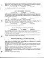
range.AdjustVRl3untilthemeterreads0.00
Measure
between2lCN4and3/CN4on DC millivolts
Vdc+30mVdc.(Note:lf measured
at another
timethisvoltagemaybe +300 mVdcdue to tempit.)
eraturedrift.Thisis nota problem,
andthereis no needto re-adjust
PowerSupplyOff
r
VSCStopped
Speed:0%
Thiscompletes
the installation
of the newcontrolboard.
't
DCCT REPLACEMENT
PROCEDURE
PowerSupplyOff
VSCStopped
Speed:0%
Locatethesmall1O{urnadjustment
trim-pot
on the DCCTand notewhichendof thewireor Buss
bar is adjacentto it. Removethe wireor Bussbar whichgoesthroughthe DCCT.Removethe
DCCTand replaceit withthe newoneso thatthe adjustment
trim-potis on the samesideof the
conductor
as withthe old DCCT.
c
PowerSupplyOn
VSCStopped
Speed:0%
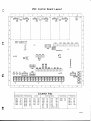
LocateVR13,
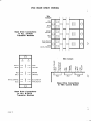
a 1Oturntrimpot,"l zeto".Referto page5 for its location.
Measure
between
2/CN4and3/CN4on DC millivolts
range.AdjustVR13untilthemeterreads0.00
Vdc+300 mVdc.(Note:lf measuredat anothertime this voltagemay be +300 mVdc due to
temperature
drift.Thisis nota problem,
and thereis no needto re-adjust
it.)
PowerSupplyOff
VSCStopped
Speed:0%
Thiscompletes
the installation
of the newDCCT.
PROCEDURE
IN P U T R E C T IF IERREPLACEM ENT
PowerSupplyOff
@
VSCStopped
Speed:0%
Alsonotetheconnections
to
Notecarefully
the orientation
moduleon the heatsink.
of the rectifier
fromthe moduleand liftit fromthe heatsink.
the module.Remove
the mounting
screw(s)
greaseto thebaseof thenewmoduleand placeit on theheatsink
Applya lightsmearof heatsink
in the sameoosition
as theold module.
Replace
lf thewiresconnectto push-on
the mounting
and re-connect
thewirescarefully.
screw(s)
terminals,
makesuretheyall makea tightconnection.
PROCEDURE
TRANSISTOR
MODULEREPLACEMENT
PowerSupplyOff
0
VSCStopped
Speed:O%
to it. Paycareful
Beforeremovingthe old transistormodule,makea noteof all the connections
attention
to the connection
of the BaseDrivewires.
module.lf thereare threemodulesremovethe Bussbars
Removethe wiresfromthe transistor
from the transistors
WITHOUT
removingthe wiresconnecting
the Bussbars to the capacitor
modules.
Remove
and thenremovethe old module(s).
the mounting
screwsfromthe module(s),
greaseto the baseof the newmodule(s).
Applya thinsmearof heatsink
screws.Turnall the screwsup
Placethe newtransistor
and insertthe mounting
on the heatsink
DO
NOT
tighten
thescrewsor thetransistor
fingertight,andthenturnthemup a littleat a time.
over
modulemaycrack.
Replacethewiringand checkit carefully.
page19
I
L