1
MELSEC iQ-R Inter-Module Synchronization
Function
Reference Manual
SAFETY PRECAUTIONS
(Read these precautions before using this product.)
Before using MELSEC iQ-R series programmable controllers, please read the manuals for the product and the relevant
manuals introduced in those manuals carefully, and pay full attention to safety to handle the product correctly.
Make sure that the end users read this manual and then keep the manual in a safe place for future reference.
CONDITIONS OF USE FOR THE PRODUCT
(1) Mitsubishi programmable controller ("the PRODUCT") shall be used in conditions;
i) where any problem, fault or failure occurring in the PRODUCT, if any, shall not lead to any major or serious accident;
and
ii) where the backup and fail-safe function are systematically or automatically provided outside of the PRODUCT for the
case of any problem, fault or failure occurring in the PRODUCT.
(2) The PRODUCT has been designed and manufactured for the purpose of being used in general industries.
MITSUBISHI SHALL HAVE NO RESPONSIBILITY OR LIABILITY (INCLUDING, BUT NOT LIMITED TO ANY AND ALL
RESPONSIBILITY OR LIABILITY BASED ON CONTRACT, WARRANTY, TORT, PRODUCT LIABILITY) FOR ANY
INJURY OR DEATH TO PERSONS OR LOSS OR DAMAGE TO PROPERTY CAUSED BY the PRODUCT THAT ARE
OPERATED OR USED IN APPLICATION NOT INTENDED OR EXCLUDED BY INSTRUCTIONS, PRECAUTIONS, OR
WARNING CONTAINED IN MITSUBISHI'S USER, INSTRUCTION AND/OR SAFETY MANUALS, TECHNICAL
BULLETINS AND GUIDELINES FOR the PRODUCT.
("Prohibited Application")
Prohibited Applications include, but not limited to, the use of the PRODUCT in;
• Nuclear Power Plants and any other power plants operated by Power companies, and/or any other cases in which the
public could be affected if any problem or fault occurs in the PRODUCT.
• Railway companies or Public service purposes, and/or any other cases in which establishment of a special quality
assurance system is required by the Purchaser or End User.
• Aircraft or Aerospace, Medical applications, Train equipment, transport equipment such as Elevator and Escalator,
Incineration and Fuel devices, Vehicles, Manned transportation, Equipment for Recreation and Amusement, and
Safety devices, handling of Nuclear or Hazardous Materials or Chemicals, Mining and Drilling, and/or other
applications where there is a significant risk of injury to the public or property.
Notwithstanding the above, restrictions Mitsubishi may in its sole discretion, authorize use of the PRODUCT in one or
more of the Prohibited Applications, provided that the usage of the PRODUCT is limited only for the specific
applications agreed to by Mitsubishi and provided further that no special quality assurance or fail-safe, redundant or
other safety features which exceed the general specifications of the PRODUCTs are required. For details, please
contact the Mitsubishi representative in your region.
1
INTRODUCTION
Thank you for purchasing the Mitsubishi MELSEC iQ-R series programmable controllers.
This manual describes the inter-module synchronization function, which controls multiple modules synchronously.
Before using this product, please read this manual and the relevant manuals carefully and develop familiarity with the
functions and performance of the MELSEC iQ-R series programmable controller to handle the product correctly.
When applying the program examples provided in this manual to an actual system, ensure the applicability and confirm that it
will not cause system control problems.
Please make sure that the end users read this manual.
Where a reference to the GX Works3 Operating Manual or the MELSEC iQ-R CPU Module User's Manual
(Startup or Application) is given, the reference should be made to the following instead:
CW Configurator Operating Manual
MELSEC iQ-R C Controller Module User's Manual (Startup)
MELSEC iQ-R C Controller Module User's Manual (Application)
2
CONTENTS
SAFETY PRECAUTIONS . . . . . . . . . . . . . . . . . . . . . . . . . . . . . . . . . . . . . . . . . . . . . . . . . . . . . . . . . . . . . . . . . . . .1
CONDITIONS OF USE FOR THE PRODUCT . . . . . . . . . . . . . . . . . . . . . . . . . . . . . . . . . . . . . . . . . . . . . . . . . . . .1
INTRODUCTION . . . . . . . . . . . . . . . . . . . . . . . . . . . . . . . . . . . . . . . . . . . . . . . . . . . . . . . . . . . . . . . . . . . . . . . . . . .2
RELEVANT MANUALS . . . . . . . . . . . . . . . . . . . . . . . . . . . . . . . . . . . . . . . . . . . . . . . . . . . . . . . . . . . . . . . . . . . . . .5
CHAPTER 1
OVERVIEW
6
CHAPTER 2
SYSTEM CONFIGURATION
8
2.1
Precautions for System Configuration . . . . . . . . . . . . . . . . . . . . . . . . . . . . . . . . . . . . . . . . . . . . . . . . . . . . . . . 8
Inter-module synchronous master . . . . . . . . . . . . . . . . . . . . . . . . . . . . . . . . . . . . . . . . . . . . . . . . . . . . . . . . . . . . . 9
2.2
Configuration Devices . . . . . . . . . . . . . . . . . . . . . . . . . . . . . . . . . . . . . . . . . . . . . . . . . . . . . . . . . . . . . . . . . . . 10
CHAPTER 3
3.1
SPECIFICATIONS
CONTENTS
TERMS . . . . . . . . . . . . . . . . . . . . . . . . . . . . . . . . . . . . . . . . . . . . . . . . . . . . . . . . . . . . . . . . . . . . . . . . . . . . . . . . . .5
11
Performance Specifications . . . . . . . . . . . . . . . . . . . . . . . . . . . . . . . . . . . . . . . . . . . . . . . . . . . . . . . . . . . . . . . 11
Inter-module synchronization accuracy . . . . . . . . . . . . . . . . . . . . . . . . . . . . . . . . . . . . . . . . . . . . . . . . . . . . . . . . 11
CHAPTER 4
PROCEDURES BEFORE OPERATION
13
CHAPTER 5
FUNCTION
15
5.1
Fixed Cycle Synchronization Function . . . . . . . . . . . . . . . . . . . . . . . . . . . . . . . . . . . . . . . . . . . . . . . . . . . . . . 15
Timing for synchronizing CPU modules . . . . . . . . . . . . . . . . . . . . . . . . . . . . . . . . . . . . . . . . . . . . . . . . . . . . . . . 15
Timing to synchronize each module . . . . . . . . . . . . . . . . . . . . . . . . . . . . . . . . . . . . . . . . . . . . . . . . . . . . . . . . . . 17
Coordination with multiple CPU system function's fixed scan communication cycle. . . . . . . . . . . . . . . . . . . . . . 23
CC-Link IE Field Network synchronous communication function . . . . . . . . . . . . . . . . . . . . . . . . . . . . . . . . . . . . 27
CHAPTER 6
PARAMETER SETTINGS
30
6.1
Inter-Module Synchronization Setting. . . . . . . . . . . . . . . . . . . . . . . . . . . . . . . . . . . . . . . . . . . . . . . . . . . . . . . 30
6.2
Multiple CPU Settings . . . . . . . . . . . . . . . . . . . . . . . . . . . . . . . . . . . . . . . . . . . . . . . . . . . . . . . . . . . . . . . . . . . . 32
6.3
Settings in CC-Link IE Field Network . . . . . . . . . . . . . . . . . . . . . . . . . . . . . . . . . . . . . . . . . . . . . . . . . . . . . . . 33
CHAPTER 7
7.1
PROGRAM EXAMPLES
34
For Single CPU System Configuration . . . . . . . . . . . . . . . . . . . . . . . . . . . . . . . . . . . . . . . . . . . . . . . . . . . . . . 34
System configuration . . . . . . . . . . . . . . . . . . . . . . . . . . . . . . . . . . . . . . . . . . . . . . . . . . . . . . . . . . . . . . . . . . . . . . 34
Programming condition . . . . . . . . . . . . . . . . . . . . . . . . . . . . . . . . . . . . . . . . . . . . . . . . . . . . . . . . . . . . . . . . . . . . 34
Parameter setting . . . . . . . . . . . . . . . . . . . . . . . . . . . . . . . . . . . . . . . . . . . . . . . . . . . . . . . . . . . . . . . . . . . . . . . . 34
Applicable labels . . . . . . . . . . . . . . . . . . . . . . . . . . . . . . . . . . . . . . . . . . . . . . . . . . . . . . . . . . . . . . . . . . . . . . . . . 35
Program. . . . . . . . . . . . . . . . . . . . . . . . . . . . . . . . . . . . . . . . . . . . . . . . . . . . . . . . . . . . . . . . . . . . . . . . . . . . . . . . 36
7.2
For Network Configuration . . . . . . . . . . . . . . . . . . . . . . . . . . . . . . . . . . . . . . . . . . . . . . . . . . . . . . . . . . . . . . . . 37
System configuration . . . . . . . . . . . . . . . . . . . . . . . . . . . . . . . . . . . . . . . . . . . . . . . . . . . . . . . . . . . . . . . . . . . . . . 37
Parameter setting . . . . . . . . . . . . . . . . . . . . . . . . . . . . . . . . . . . . . . . . . . . . . . . . . . . . . . . . . . . . . . . . . . . . . . . . 37
Applicable labels . . . . . . . . . . . . . . . . . . . . . . . . . . . . . . . . . . . . . . . . . . . . . . . . . . . . . . . . . . . . . . . . . . . . . . . . . 38
Program. . . . . . . . . . . . . . . . . . . . . . . . . . . . . . . . . . . . . . . . . . . . . . . . . . . . . . . . . . . . . . . . . . . . . . . . . . . . . . . . 39
CHAPTER 8
8.1
TROUBLESHOOTING
40
Error Processing and Recovery Methods . . . . . . . . . . . . . . . . . . . . . . . . . . . . . . . . . . . . . . . . . . . . . . . . . . . . 40
Inter-module synchronous interrupt program does not run . . . . . . . . . . . . . . . . . . . . . . . . . . . . . . . . . . . . . . . . . 41
A specific module is not synchronized. . . . . . . . . . . . . . . . . . . . . . . . . . . . . . . . . . . . . . . . . . . . . . . . . . . . . . . . . 41
3
8.2
RAS Function. . . . . . . . . . . . . . . . . . . . . . . . . . . . . . . . . . . . . . . . . . . . . . . . . . . . . . . . . . . . . . . . . . . . . . . . . . . 42
Inter-module synchronous interrupt program execution time monitor . . . . . . . . . . . . . . . . . . . . . . . . . . . . . . . . . 42
Inter-module synchronization signal error monitoring . . . . . . . . . . . . . . . . . . . . . . . . . . . . . . . . . . . . . . . . . . . . . 42
Monitor of output exceeding inter-module synchronization cycle . . . . . . . . . . . . . . . . . . . . . . . . . . . . . . . . . . . . 42
Cyclic monitor . . . . . . . . . . . . . . . . . . . . . . . . . . . . . . . . . . . . . . . . . . . . . . . . . . . . . . . . . . . . . . . . . . . . . . . . . . . 42
APPENDIX
44
Appendix 1 Processing Time . . . . . . . . . . . . . . . . . . . . . . . . . . . . . . . . . . . . . . . . . . . . . . . . . . . . . . . . . . . . . . . . . . . 44
Overhead time for executing interrupt program. . . . . . . . . . . . . . . . . . . . . . . . . . . . . . . . . . . . . . . . . . . . . . . . . . 44
Refresh processing time . . . . . . . . . . . . . . . . . . . . . . . . . . . . . . . . . . . . . . . . . . . . . . . . . . . . . . . . . . . . . . . . . . . 44
Instruction processing time in interrupt program . . . . . . . . . . . . . . . . . . . . . . . . . . . . . . . . . . . . . . . . . . . . . . . . . 44
INDEX
46
REVISIONS . . . . . . . . . . . . . . . . . . . . . . . . . . . . . . . . . . . . . . . . . . . . . . . . . . . . . . . . . . . . . . . . . . . . . . . . . . . . . .48
WARRANTY . . . . . . . . . . . . . . . . . . . . . . . . . . . . . . . . . . . . . . . . . . . . . . . . . . . . . . . . . . . . . . . . . . . . . . . . . . . . .49
TRADEMARKS . . . . . . . . . . . . . . . . . . . . . . . . . . . . . . . . . . . . . . . . . . . . . . . . . . . . . . . . . . . . . . . . . . . . . . . . . . .50
4
RELEVANT MANUALS
Manual name [manual number]
Description
Available form
MELSEC iQ-R Inter-Module Synchronization Function
Reference Manual
[SH-081401ENG] (this manual)
Inter-module synchronization function, which controls multiple
modules synchronously
e-Manual
EPUB
PDF
MELSEC iQ-R CPU Module User's Manual (Startup)
[SH-081263ENG]
Performance specifications, procedures before operation, and
troubleshooting of the CPU module
Print book
MELSEC iQ-R C Controller Module User's Manual
(Application)
[SH-081369ENG]
Functions, devices, and parameters of C Controller module
Print book
e-Manual
EPUB
PDF
e-Manual
EPUB
PDF
e-Manual refers to the Mitsubishi FA electronic book manuals that can be browsed using a dedicated tool. eManual has the following features:
• Required information can be cross-searched in multiple manuals.
• Other manuals can be accessed from the links in the manual.
• The hardware specifications of each part can be found from the product figures.
• Pages that users often browse can be bookmarked.
TERMS
Unless otherwise specified, this manual uses the following terms.
Term
Description
A/D converter module
Another name for the analog-digital converter module
CPU module
A generic term for the MELSEC iQ-R series CPU module
C Controller module
A generic term for the MELSEC iQ-R series C Controller module
D/A converter module
Another name for the digital-analog converter module
RAS
The abbreviation for Reliability, Availability, and Serviceability. This term refers to usability of automated
equipment.
Intelligent function module
A module that has functions other than input and output, such as an A/D converter module and D/A converter
module
Engineering tool
The product name of the software package for the MELSEC programmable controllers
Control CPU
A CPU module that controls connected I/O modules and intelligent function modules. In a multiple CPU system,
there are multiple CPU modules and each connected module can be controlled by a different CPU module.
Global label
A label that is valid for all the program data when multiple program data are created in the project. The global
label has two types: a module specific label (module label), which is generated automatically by GX Works3, and
an optional label, which can be created for any specified device.
Cyclic transmission
A function by which data are periodically exchanged among stations on the network using link devices
Slave station
A generic term for a local station, remote I/O station, remote device station, and intelligent device station
Device
A device (X, Y, M, D, or others) in a CPU module
Master/local module
A generic term for the RJ71GF11-T2 CC-Link IE Field Network master/local module and RJ71EN71 (when the
CC-Link IE Field Network function is used)
Master station
A station that controls the entire network. This station can perform cyclic transmission and transient transmission
with all stations. Only one master station can be used in a network.
Module label
A label that represents one of memory areas (I/O signals and buffer memory areas) specific to each module in a
given character string. For the module used, GX Works3 automatically generates this label, which can be used
as a global label.
Link scan time
Time required for all the stations on the network to transmit data.
Link device
A device (RX, RY, RWr, RWw, SB, SW) in a module on CC-Link IE Field Network
Local station
A station that performs cyclic transmission and transient transmission with the master station and other local
stations.
5
1
OVERVIEW
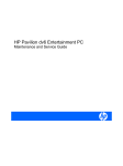
The inter-module synchronization function adjusts the control timing for the signals between multiple modules. When this
function is used, the synchronization target module can match the input or output timing to the inter-module synchronization
cycle. The inter-module synchronization cycle is a fixed scan interval for the inter-module synchronization function. The
multiple CPU system function's fixed communication interval and the CC-Link IE Field Network synchronous communication
function can be coordinated with the inter-module synchronization cycle.
Output module
Input module
Programmable
controller CPU
A/D converter module
D/A converter module
Inter-module
synchronization cycle
Programmable
controller CPU
Inter-module
synchronization cycle
Program
Inter-module synchronous
interrupt program (I44)
Operation processing
(1)
A/D converter module
(set as a synchronization target)
D/A converter module
(set as a synchronization target)
Input module
(set as a synchronization target)
Output module
(set as a synchronization target)
Operation processing
Operation processing
(1)
Input
Output
Input
Output
Input
Input
Output
Output
Output
conversion
Input
Output
conversion
Output
(2)
(1) Refreshing is executed before and after the inter-module synchronous interrupt program (I44).
(2) The input process and output process are performed at the timing of the inter-module synchronization cycle.
6
1 OVERVIEW
Input
Output
MEMO
1
1 OVERVIEW
7
2
SYSTEM CONFIGURATION
Shows the system configuration for the inter-module synchronization function.
2.1
Precautions for System Configuration
Lists precautions for configuring the inter-module synchronization function system.
Item
Description
Modules targeted for inter-module synchronization function*1
This function can be used only with the MELSEC iQ-R Series modules.
(Page 10 Configuration Devices)
For
configuration
that uses the
network
module as the
synchronization
target module.
*1
*2
*3
Network compatible with inter-module synchronization
function
Number of network modules that can be specified as
target module for inter-module synchronization function
(Per station include those on extension base unit.)*2*3
Only CC-Link IE Field Network
• Master station modules: 8 modules
• Local station modules: 1 module*6
Network transmission path format compatible with intermodule synchronization function
Only the following network topology can be used.
• Line topology
• Star topology*4
• Line topology and star topology combination*4
Mounting position of local station module in
synchronization target network module
The local station can be mounted only on the main base unit. (Local stations on
the extension base unit cannot be synchronized.)
Types of stations supported with inter-module
synchronization function*5
Only master station and local station
Time required for inter-module synchronization function
to start (rising edge)
Max. 20 seconds
This is not restricted by the module mounting position, maximum number of mountable modules, or the number of CPU modules when
using a multiple CPU system configuration. (Same as when not using the inter-module synchronization function.) ( MELSEC iQ-R
Module Configuration Manual)
In the multiple CPU system, the inter-module synchronization function can be used only by the network module controlled by the CPU
No.1.
If the local station is designated as the module targeted for the inter-module synchronization function, the master station on the same
base unit as the local station cannot be set as a module targeted for the inter-module synchronization function.
Master station
Local station
Master station
Local station
*4
*5
*6
8
A hub compatible with the inter-module synchronization function must be used. ( MELSEC iQ-R Ethernet/CC-Link IE User's Manual
(Startup))
Shows the type of station that can be selected with the station type setting. ( MELSEC iQ-R CC-Link IE Field Network User's Manual
(Application))
To use the module on the local station as the synchronization target module, Synchronous Master Setting within the Modules is required.
(Page 9 Inter-module synchronous master, Page 30 Inter-Module Synchronization Setting)
2 SYSTEM CONFIGURATION
2.1 Precautions for System Configuration
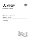
Inter-module synchronous master
The inter-module synchronous master is a module that issues the inter-module synchronization command. Normally, the CPU
module becomes the inter-module synchronous master. (For the multiple CPU system configuration, the CPU module on the
extreme left, for which "Synchronize" is set in "Select the Synchronous Target Unit" of "Synchronization Setting within the
2
Modules", becomes the inter-module synchronous master.) Note that if a module on the local station is used as the
synchronization target, the master station becomes the inter-module synchronous master because the CC-Link IE Field
Network module on the local station operates by receiving the command from the master station.
Inter-module synchronization command
Master station
Normally, the CPU module becomes
the inter-module synchronous master
and issues the inter-module
synchronization command.
The Network module sends
the inter-module synchronization
command to each station.
Inter-module synchronization command
Local station
Slave station
Slave station
Inter-module synchronization command
On the local station, the Network module receives
the command from the master station, and issues
the inter-module synchronization command as
the inter-module synchronous master.
2 SYSTEM CONFIGURATION
2.1 Precautions for System Configuration
9
2.2
Configuration Devices
Shows the modules that can be synchronously controlled with the inter-module synchronization function.
Part name
Model name
CPU module
Programmable controller CPU
•
•
•
•
•
•
•
•
•
•
R04CPU
R04ENCPU
R08CPU
R08ENCPU
R16CPU
R16ENCPU
R32CPU
R32ENCPU
R120CPU
R120ENCPU
Process CPU
•
•
•
•
R08PCPU
R16PCPU
R32PCPU
R120PCPU
Motion CPU
• R16MTCPU
• R32MTCPU
C Controller module
Network module
Master/local module
I/O module
AC input module
*1
• RJ71GF11-T2
• RJ71EN71*1
RX10
DC input module
• RX40C7
• RX41C4
DC high-speed input module
• RX40PC6H
• RX40NC6H
Contact output module
Intelligent function module
R12CCPU-V
RY10R2
Transistor output module
•
•
•
•
RY40NT5P
RY41NT2P
RY40PT5P
RY41PT1P
A/D converter module
• R60AD4
• R60ADI8
• R60ADV8
D/A converter module
• R60DA4
• R60DAI8
• R60DAV8
Simple motion module
•
•
•
•
High-speed counter module
• RD62P2
• RD62D2
• RD62P2E
Positioning module
•
•
•
•
RD77MS2
RD77MS4
RD77MS8
RD77MS16
RD75P2
RD75P4
RD75D2
RD75D4
Usable only when operating as the CC-Link IE Field Network.
A module other than those listed in the table can be mounted on the system as long as it is not a module that
is synchronously controlled with the inter-module synchronization function.
10
2 SYSTEM CONFIGURATION
2.2 Configuration Devices
3
SPECIFICATIONS
Shows the specifications for the inter-module synchronization function.
3.1
Performance Specifications
Shows the performance specifications for the inter-module synchronization function.
3
Item
Performance value
Inter-module synchronization cycle
100s to 10ms
Inter-module synchronization accuracy
Calculate the accuracy with the inter-module synchronization accuracy formula. (Page 12 Inter-module
synchronization accuracy calculation formula)
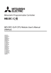
Inter-module synchronization accuracy
The accuracy is the difference that each module recognizes the synchronization point and the time of the synchronization
point. In the case of the following output module, the inter-module synchronization accuracy is Tmax-T0 in the positive
direction, and T0-Tmin in the negative direction.
• T: Inter-module synchronization accuracy
• T0: Synchronization point time
• Tmin: Time that an output module recognizes synchronization point
(Min.)
• Tmax: Time that an output module recognizes synchronization
point (Max.)
• Tcyc: Inter-module synchronization cycle
• Tres: Output module response time
T
Tmin
T0
Tmax
Tcyc
Tcyc
Tres
ON
Output for when the
inter-module synchronization
OFF
accuracy of the output
module is maximum
(in the negative direction)
Tres
ON
Output for when the
inter-module synchronization
accuracy of the output
OFF
module is maximum
(in the positive direction)
The actual external output is output with the following time lag.
Inter-module synchronization accuracy + output module response time (Tres)
• Each module starts the process at the inter-module synchronization functions' start timing, so the input or
output is made after the response time from that inter-module synchronization function's start timing.
• For details on each module's response time (Tres), refer to each module's manual.
3 SPECIFICATIONS
3.1 Performance Specifications
11
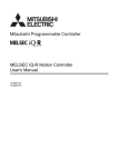
Inter-module synchronization accuracy calculation formula
Shows the calculation formula for the inter-module synchronization accuracy. Use as a guide to set the inter-module
synchronization cycle.
■When not going through a network module
T=Tcyc2.410-4+Nr80+150
• T: Inter-module synchronization accuracy (ns)
• Tcyc: Inter-module synchronization cycle (ns)
• Nr: Number of stages in extension base unit in which the module for calculating the inter-module synchronization accuracy
is mounted*1
*1
This is 0 for the main base unit.
■When going through network module
T=Tcyc2.410-4+Nr80+Ns12+700
• T: Inter-module synchronization accuracy (ns)
• Tcyc: Inter-module synchronization cycle (ns)
• Nr: Number of stages in extension base unit in which the module for calculating the inter-module synchronization accuracy
is mounted*1
• Ns: Number of transit stations from the master station in which the module for calculating the inter-module synchronization
accuracy +1*2
*1
*2
This is 0 for the main base unit.
The number of relay stations from the master station refers to the number of stations physically related from the master station to the
relevant station when using the following type of line topology or line topology/star topology combination.
Number of relay stations
from the master station: 1
Number of relay stations
from the master station: 0
Slave
station
Slave
station
Master
station
Number of relay stations
from the master station: 0
Number of relay stations
from the master station: 1
Number of relay stations
from the master station: 2
Slave
station
Slave
station
Slave
station
Obtain the inter-module synchronization accuracy for the module mounted in the master station with the
"When not going through network module" method.
12
3 SPECIFICATIONS
3.1 Performance Specifications
4
PROCEDURES BEFORE OPERATION
This section describes the procedures for using the inter-module synchronization function.
1.
Starting up the engineering tool
Connect the personal computer in which the engineering tool is installed to the CPU module, and start up the engineering tool.
( GX Works3 Operating Manual)
For details on the preparations for starting up the engineering tool (mounting the modules, wiring each device,
turning the system power ON, etc.), refer to the following.
4
MELSEC iQ-R CPU Module User's Manual (Startup)
2.
Setting the applicable system
Set the system used in the unit configuration drawing. ( GX Works3 Operating Manual) When using the multiple CPU
system configuration, set the system parameters for all CPU modules.) ( MELSEC iQ-R CPU Module User's Manual
(Application))
3.
Setting the inter-module synchronization function
Set the parameters required for using the inter-module synchronization function.
• Inter-module synchronization setting (Page 30 Inter-Module Synchronization Setting)
• If necessary, set the CPU parameters and module parameters. (Manual for each module)
• To coordinate the multiple CPU system function's fixed scan communication cycle with the inter-module synchronization
cycle, set the fixed scan communication setting. (Page 32 Multiple CPU Settings)
• To coordinate the CC-Link IE Field Network synchronous communication function with the inter-module synchronization
cycle, set the CC-Link IE Field Network master station. (Page 33 Settings in CC-Link IE Field Network)
4.
Programming
Create the inter-module synchronous interrupt program. To exchange the data used with the inter-module synchronization
function between the multiple CPU systems, create a program for exchanging data.
5.
RAS setting
If necessary, set to monitor the inter-module synchronous interrupt program's execution time. (Page 42 Inter-module
synchronous interrupt program execution time monitor)
6.
Writing the parameters and programs
Write the parameters set with the engineering tool and the created program into the CPU module. ( GX Works3 Operating
Manual)) When using the multiple CPU system configuration, the parameter settings and program must be written into each
CPU module for CPU No. 2 to 4.
7.
Restarting the system
Restart the system with one of the following methods.
• Power OFFONRUN
• Reset the CPU moduleRUN
8.
Monitoring and diagnosis
If necessary, confirm the operation of the inter-module synchronization function with the system monitor or the interrupt
program monitor list for each CPU module. (Page 40 Error Processing and Recovery Methods)
4 PROCEDURES BEFORE OPERATION
13
MEMO
14
4 PROCEDURES BEFORE OPERATION
5
FUNCTION
Shows the details of the inter-module synchronization function.
5.1
Fixed Cycle Synchronization Function
Multiple modules are synchronized at the inter-module synchronization cycle timing set with the parameters. The data is
exchanged and the input/output is control at a fixed cycle. By using this function, the encoder input can be collected at a fixedtime so data is retrieved at an accurate speed. In addition, the input/output timing is accurately known so highly accurate
model prediction control is possible.
Timing for synchronizing CPU modules
The CPU modules execute an inter-module synchronous interrupt program at each inter-module synchronization cycle.
5
(Page 16 Inter-module synchronous interrupt) The CPU module and each module are synchronized by refreshing. This is
performed before or after the inter-module synchronous interrupt program. With this, the input data can be retrieved and the
output data can be written at the inter-module synchronization cycle timing.
When using C Controller module, refer to the following manual.
MELSEC iQ-R C Controller Module User's Manual (Application)
Inter-module
synchronization cycle
Inter-module synchronous
interrupt program
execution time
CPU module
Normal program
Interrupted
Inter-module synchronous interrupt program
Input
refresh
External device
External device
Input
Operation
processing
Output
refresh
Input
Input
Input
Input module
Output
Output
Output
Output
External device
External device
Output module
• The CC-Link IE Field Network module's input signal (X) and output signal (Y) are refreshed at the END
process.
• For details on the refresh operation and settings, refer to each module's manual.
5 FUNCTION
5.1 Fixed Cycle Synchronization Function
15
Inter-module synchronous interrupt
The interrupt program is executed at the inter-module synchronization cycle timing set in the parameters. The interrupt
program executed at each inter-module synchronization cycle is called the inter-module synchronous interrupt program. For
details on the inter-module synchronous interrupt program, refer to the manual for each CPU module.
• Write the program for controlling the synchronization target in the inter-module synchronous interrupt
program.
• The operation when an interrupt cause occurs and the methods of creating the program, etc., are the same
as a normal interrupt program.
■Execution timing
The inter-module synchronous interrupt program is executed at the inter-module synchronization cycle timing. The intermodule synchronization cycle can be changed with the parameter settings. (Page 30 Inter-Module Synchronization
Setting)
■Multiple interrupt
For details on the inter-module synchronization (I44) multiple interrupt function, refer to the following.
MELSEC iQ-R CPU Module User's Manual (Application)
Refresh timing according to CPU module's operation status
This section shows the refresh timing according to the CPU module operation status.
For C Controller module, the refresh timing is before and after an inter-module synchronous interrupt program
since an inter-module synchronous interrupt program is executed even when the operating status of C
Controller module is STOP. For more details, refer to the following manual.
MELSEC iQ-R C Controller Module User’s Manual (Application)
■(RUNSTOP) operation at STOP
At STOP*1, the CPU module stops the execution of the inter-module synchronous interrupt program, and turns the output
OFF. Refreshing is executed even during STOP. Note that refreshing will not be executed the specified inter-module
synchronization cycle (fixed cycle), but will be executed at the END process.
*1
This includes CPU module stop errors.
■STOPRUN operation*1
The CPU module issues the inter-module synchronization start instruction to each module at the inter-module synchronization
cycle after STOPRUN. The inter-module synchronous interrupt program execution starts at the next inter-module
synchronization cycle. The refresh timing changes from the END process to before and after the inter-module synchronous
interrupt program.
*1
16
The operation is the same at Power ONRUN.
5 FUNCTION
5.1 Fixed Cycle Synchronization Function
Timing to synchronize each module
Shows the timing to synchronize each module.
Input module
The input module retrieves the input module at the inter-module synchronization cycle start timing, and holds the input value
during the inter-module synchronization cycle. (The input value is retrieved only once during the inter-module synchronization
cycle.) By reading the input value (input signal) from the inter-module synchronous interrupt program, multiple modules can
read the retrieved value at the same timing.
Inter-module
synchronization cycle
Inter-module
synchronization cycle
Inter-module synchronous
interrupt program
Inter-module synchronous
interrupt program
CPU module
Input
refresh
Operation
processing
Output
refresh
Normal program
External input signal to X0
OFF
Normal program
5
OFF
ON
ON
OFF
Acquire and hold an input value.
Acquire and hold an input value.
X1
Output
refresh
ON
X0
External input signal to X1
Operation
processing
Read an input value.
Read an input value.
ON
ON
Input
refresh
ON
Acquire and hold an input value.
ON
ON
ON
5 FUNCTION
5.1 Fixed Cycle Synchronization Function
17
A/D converter module
During the interval from the inter-module synchronization cycle start timing to execution of the inter-module synchronous
interrupt program, the latest A/D conversion value is retrieved and stored in the synchronization latch digital operation value.
The synchronization latch digital operation value is held during the inter-module synchronization cycle. By reading the
synchronization latch digital operation value from the inter-module synchronous interrupt program, multiple modules can read
the A/D conversion value at the same timing.
Inter-module
synchronization cycle
Inter-module
synchronization cycle
Inter-module synchronous
interrupt program
CPU module
Input
refresh
Operation
processing
Output
refresh
Inter-module synchronous
interrupt program
Normal program
A/D conversion
A/D conversion
value
1
value 1
A/D conversion A/D conversion
value 2
A/D conversion value
value1
Synchronization latch digital output value
A/D conversion A/D conversion
value 3
value 4
A/D conversion value 1
Operation
processing
Output
refresh
Normal program
Read an A/D conversion value.
Read an A/D conversion value.
Analog input module No.1 CH1
Input
refresh
A/D conversion
A/D conversion
value
5
value 5
A/D conversion
value 5
A/D conversion
value 6
A/D conversion
value 7
A/D conversion
value 8
A/D conversion
value 9
A/D conversion value 5
Analog input module No.2 CH1A/D conversion A/D conversion A/D conversion A/D conversion A/D conversion A/D conversion A/D conversion A/D conversion
value 2
value 3
value 4
value 5
value 6
value 7
value 8
value 1
A/D conversion value
Synchronization latch digital output value
A/D conversion value 1
A/D conversion
value 10
A/D conversion
value 9
A/D conversion value 5
For details on the inter-module synchronization function in the A/D converter module, refer to the following.
Each A/D converter module manual
18
5 FUNCTION
5.1 Fixed Cycle Synchronization Function
High-speed counter module
The value is latched in synchronization with the falling edge of the inter-module synchronization control signal. The latched
value is stored in the buffer memory. The normal count operation is executed even when using the inter-module
synchronization signal. The latch target and storage destination buffer memory differ according to the operation mode.
Operation mode
Latch timing
Latch target
Storage destination buffer memory name*1
Pulse count mode
Falling edge of inter-module
synchronization control signal
Current counter value
Synchronization latch count value
Pulse measurement mode
Falling edge of inter-module
synchronization control signal
Measured pulse value
Synchronization measured pulse value
*1
The value is updated only at the falling edge of the inter-module synchronization control signal regardless of the ON/OFF state of the
count enable instruction pulse measurement instruction.
■Pulse count mode (Synchronization latch counter function)
The latest current counter value is retrieved at the inter-module synchronization cycle start timing, and is held during the intermodule synchronization cycle. By reading the synchronization latch counter value from the inter-module synchronous
5
interrupt program, multiple modules can read the retrieved current count value at the same timing.
Inter-module
synchronization cycle
Inter-module synchronous
interrupt program
Inter-module synchronous
interrupt program
CPU module Input
refresh
Operation
processing
Output
refresh
Inter-module
synchronization cycle
Normal program
Read a synchronization latch count value.
Count value 1
Input
refresh
Operation
processing
Output
refresh
Normal program
Read a synchronization latch count value.
Count value 2
High-speed counter module No.1 CH1
Present value
Synchronization latch count value
Count value 1
Count value 2
Count value 1
Count value 2
High-speed counter module No.2 CH1
Present value
Synchronization latch count value
5 FUNCTION
5.1 Fixed Cycle Synchronization Function
19
■Pulse measurement mode (Synchronous pulse measurement function)
The pulse measurement value of the function input terminal's input pulse is retrieved at the inter-module synchronization cycle
start timing. The pulse measurement interval can be selected from four patterns: ON width, OFF width, rising edge to rising
edge, or falling edge to falling edge. (The synchronization latch pulse measurement value is updated only once during the
inter-module synchronization cycle.) By reading the synchronization latch pulse measurement value from the inter-module
synchronous interrupt program, the pulse measurement value of the input pulse just before the inter-module synchronization
cycle is started can be read out.
Inter-module
synchronization cycle
Inter-module
synchronization cycle
Inter-module synchronous interrupt program
CPU module
Input
refresh
Operation
processing
Output
refresh
Inter-module synchronous interrupt program
Normal program
Input
refresh
Read a synchronization measured pulse value.
Synchronization latch measured pulse value
High-speed counter module No.2 CH1
sured value 1
Measured pulse value
Synchronization latch measured pulse value
20
5 FUNCTION
5.1 Fixed Cycle Synchronization Function
Output
refresh
Normal program
Read a synchronization measured pulse value.
Measured value 1
High-speed counter module No.1 CH1
Measured value 1
Measured pulse value
Operation
processing
Measured value 3
Measured value 2
Measured value 3
Measured value 1
Measured value 2
Measured value 1
Measured value 5
Measured value 4
Measured value 3
Measured value 3
Measured value 4
Measured value 5
Measured value 3
Output module
The output module's external output value (ON/OFF) is updated at the inter-module synchronization cycle start timing. (The
output value is updated only once during the inter-module synchronization cycle.) By setting the output value from the intermodule synchronous interrupt program, several modules can output the setting value externally at the same value. The
external output value is updated at the start timing of the inter-module synchronization cycle after the output that is set in the
inter-module synchronous interrupt program.
Inter-module
synchronization cycle
CPU module
Inter-module
synchronization cycle
Inter-module synchronous
interrupt program
Inter-module synchronous
interrupt program
Input
refresh
Operation
processing
Output
refresh
Normal program
Input
refresh
Operation
processing
Output
refresh
Set an output value.
Set an output value.
ON
OFF
OFF
ON
External output
signal from Y0
Y0
Y1
5
OFF
ON
ON
ON
OFF
Update an output value.
External output
signal from Y1
Normal program
Update an output value.
Update an output value.
OFF
ON
OFF
ON
OFF
D/A converter module
After execution of the inter-module synchronous interrupt program is completed, the output preparation process is executed
suing the digital value set in the D/A converter module. The analog signal is output at the start timing of the next inter-module
synchronization cycle after the inter-module synchronization cycle. (The output preparation process is executed only once
during the inter-module synchronization cycle.) By writing the digital value from the inter-module synchronous interrupt
program to multiple D/A converter modules, multiple modules can output the analog signal at the same timing.
Inter-module
synchronization cycle
Inter-module
synchronization cycle
Inter-module synchronous
interrupt program
CPU module
Input
refresh
Operation
processing
Output
refresh
Inter-module synchronous
interrupt program
Normal program
Input
refresh
Set a digital value.
Digital value 2
Analog output module No.1 CH1
Analog output signal
Output preparation
processing
Internal processing
Digital value
Digital value 1
Digital value 2
Operation
processing
Output
refresh
Normal program
Set a digital value.
Digital value 3
Output preparation
processing
Digital value 3
Analog output module No.2 CH1
Analog output signal
Output preparation
processing
Internal processing
Digital value
Digital value 1
Digital value 2
Output preparation
processing
Digital value 3
For details on the inter-module synchronization function in the D/A converter module, refer to the following.
Manual for each D/A converter module
5 FUNCTION
5.1 Fixed Cycle Synchronization Function
21
Positioning module
The pulse output is started at the inter-module synchronization cycle after the positioning start trigger is received. Note that
the pulse output start timing is adjusted only to the inter-module synchronization cycle. After starting, each positioning module
controls the positioning independently.
Inter-module
synchronization cycle
Inter-module
synchronization cycle
Inter-module synchronous
interrupt program
CPU module
Input
refresh
Operation
processing
Output
refresh
Inter-module synchronous
interrupt program
Normal program
Input
refresh
Operation
processing
Output
refresh
Inter-module
synchronization cycle
Inter-module synchronous
interrupt program
Normal program
Input
refresh
Operation
processing
Output
refresh
Normal program
Start pulse
output.
Positioning start
...
Positioning module No.1 axis 1
Pulse output to an external
source
Axis operation status
Standby
Analyzing
Start pulse
output.
...
Positioning module No.2 axis 4
Pulse output to an external
source
Axis operation status
Standby
Analyzing
For details on the positioning module's inter-module synchronization function, refer to the following.
Manual for each positioning module
Simple motion module
There is no need to match the inter-module synchronization cycle to the simple motion operation cycle. Note that the buffer
memory value is updated and referred to at the simple motion operation cycle.
■When the inter-module synchronization cycle is faster than the simple motion operation cycle
The monitor data is updated at each simple motion operation cycle, and the control data, etc., is not processed if only the
inter-module synchronization cycle is ON for only one scan, etc.
■When the inter-module synchronization cycle is slower than the simple motion operation
cycle
Data may be skipped if the monitor data changes only during 1 simple motion operation cycle.
For details on the inter-module synchronization function in the simple motion module, refer to the following.
Manual for simple motion module
22
5 FUNCTION
5.1 Fixed Cycle Synchronization Function
Coordination with multiple CPU system function's fixed scan
communication cycle
The fixed scan communication cycle for the multiple CPU system function can be set to the inter-module synchronization
cycle.
When using C Controller module, refer to the following manual.
MELSEC iQ-R C Controller Module User's Manual (Application)
Programmable controller CPU
By setting the fixed scan communication cycle for the multiple CPU system function to the inter-module synchronization cycle,
modules with different control CPUs can input and output in synchronization. Coordination with the fixed scan communication
cycle for the multiple CPU system function is set with the parameters. (Page 32 Multiple CPU Settings)
A/D converter module
(controlled by CPU No.1)
Programmable
controller CPU No.1
Programmable
controller CPU No.2
A/D converter module
(controlled by CPU No.2)
5
Synchronization of I/O operation is
possible between modules controlled
by different CPU modules.
For details on the multiple CPU system function, refer to the following.
MELSEC iQ-R CPU Module User's Manual (Application)
5 FUNCTION
5.1 Fixed Cycle Synchronization Function
23
■Program operation
When the inter-module synchronization cycle is coordinated with the fixed scan communication cycle for the multiple CPU
system function, the multiple CPU synchronous interrupt program (I45) and inter-module synchronous interrupt program (I44)
are executed between the inter-module synchronization cycles. The programs are executed in the order of multiple CPU
synchronous interrupt program (I45) and inter-module synchronous interrupt program (I44). It takes two inter-module
synchronization cycles for the host CPU module's retrieval data to reach another CPU module. To synchronize the output
between the CPU modules, the output timing from the host's control module must be delayed by two inter-module
synchronization cycles.
(1)
CPU No.1
Program execution
processing
Multiple CPU synchronous Inter-module synchronous
interrupt program
interrupt program
Normal program
Input
Input data
module
Fixed scan communication cycle
Inter-module synchronization cycle
Fixed scan communication cycle
Inter-module synchronization cycle
Operation processing
Input Operation Output
refresh processing refresh
1 Acquire an input value.
Multiple CPU synchronous Inter-module synchronous
interrupt program
interrupt program
Normal program
Do not set data here even
though data can be output
at the next inter-module
synchronization cycle.
Operation processing
Output data
Input Operation Output
refresh processing refresh
Fixed scan communication cycle
Inter-module synchronization cycle
Multiple CPU synchronous Inter-module synchronous
interrupt program
interrupt program
Normal program
Operation processing
Input Operation Output
refresh processing refresh
2 Write data to the fixed Do not set data here even
scan communication though data can be output Output data
area.
at the next inter-module
Normal program
Output data
5 Set an output value.
synchronization cycle.
Input data
Fixed scan communication area
3 Fixed scan communication
Fixed scan communication
Fixed scan communication
Fixed scan communication
Fixed scan communication
Fixed scan communication area
Input data
Multiple CPU synchronous Inter-module synchronous
interrupt program
interrupt program
Multiple CPU synchronous Inter-module synchronous
interrupt program
interrupt program
Normal program
Operation processing
CPU No.2
Program execution
processing
Input Operation Output
refresh processing refresh
Normal program
Operation processing
Input Operation Output
refresh processing refresh
4 Read data from the fixed scan communication area.
Multiple CPU synchronous Inter-module synchronous
interrupt program
interrupt program
Normal program
Operation processing
Input Operation Output
refresh processing refresh
(2)
Normal program
Output data
5 Set an output value.
Fixed scan communication cycle
Fixed scan communication cycle
Fixed scan communication cycle
Inter-module synchronization cycle
Inter-module synchronization cycle
Inter-module synchronization cycle
Output
module
Create the program where the two cycles of the output differences are offset.
(1) Write the input value into the CPU No.1's fixed scan communication area.
(2) Read the CPU No.1's fixed scan communication area, and set the output value.
An inter-module synchronization function FB is provided to absorb the two-cycle output difference. To delay
the output timing of the host's control module by two inter-module synchronization cycles, create a program
using the inter-module synchronization function's FB. (MELSEC iQ-R CPU Module Function Block
Reference)
24
5 FUNCTION
5.1 Fixed Cycle Synchronization Function
■Precautions
This section describes the precautions for coordinating with the multiple CPU system function's fixed scan communication
cycle.
• Even if the input/output settings for other than the group are enabled with another CPU module's program, the input or
output cannot be retrieved from the synchronization target's module. Data can be read with direct specifications such as the
DX, DY, Un\Gn or FROM instructions, but the data might be inconsistent.
• To synchronize the start timings of inter-module synchronization function for all CPU modules and all stations, set the CPU
parameter to synchronize the rising of each module, and set the system parameter to synchronize the rising of all CPU
modules.
• By setting "Fixed Scan Communication Function and Inter-module Synchronization Function" to "Cooperate" in multiple
CPU settings of system parameter, the fixed scan communication cycle of multiple CPU system function operates
according to the inter-module synchronization cycle of the inter-module synchronization function, and the both functions are
controlled to operate at the same timing. (In this case, the fixed scan communication cycle of multiple CPU system function
cannot be set.) Note that the number of program executions is different even though "Cooperate" is set in multiple CPU
5
settings of system parameter, because the start timings of interrupt program executions are different between the intermodule synchronous interrupt (I44) and the multiple CPU synchronous interrupt (I45). For details on the start timings, refer
to Page 16 Refresh timing according to CPU module's operation status. For details on the operations of interrupt programs
(such as during interrupt disabled time), refer to the MELSEC iQ-R CPU Module User's Manual (Application).
• Control with synchronized timing is not possible without synchronizing with the inter-module synchronization function even
if the same value is set for the multiple CPU system function's fixed scan communication cycle and the inter-module
synchronization cycle.
Motion CPU
The execution timing for the motion operation or motion SFC event task (fixed cycle task) is as follows when the multiple CPU
system function's fixed scan communication cycle or inter-module synchronization cycle is used.
Item
Inter-module synchronization cycle
Disable
Enable
Do not synchronize
with the selected intermodule
synchronization target
module
Fixed scan
communication
cycle for multiple
CPU system
function
*1
Disable
Enable
Synchronize with the
selected inter-module
synchronization target
module
Cycle unique to Motion CPU
Synchronization with intermodule synchronization
cycle*1
Do not synchronize
with inter-module
synchronization
cycle
Fixed scan communication cycle for multiple CPU system
function*1 (Page 26 Timing example 1)
Error occurs
Synchronize with
inter-module
synchronization
cycle
Setting not possible
Multiple CPU system function's fixed scan communication
cycle = synchronization with inter-module synchronization
cycle*1 (Page 26 Timing example 2, Page 26 Timing
example 3)
When the motion operation cycle and the multiple CPU system function's fixed scan communication cycle or inter-module
synchronization cycle differ, the start timing of the longer cycle is always synchronized with the start timing of the shorter cycle.
Ex.
When using the following setting with programmable controller CPU (CPU No.1) and Motion CPU (CPU No.2)
• Inter-module synchronization cycle = 1.00ms, multiple CPU system function's fixed scan communication cycle = 0.888ms
• Set the Motion CPU (CPU No.2) to "Do not Synchronize" in the inter-module synchronization target module selection
The communication cycle of the programmable controller CPU (CPU No.1) and Motion CPU (CPU No.2) multiple CPU
synchronous interrupt program (I45) and CPU buffer memory access device (U3En\HGn) is a 0.888ms cycle.
The programmable controller CPU (CPU No.1) inter-module synchronous interrupt program (I44) has a 1.00ms cycle.
The Motion CPU operation cycle is a cycle synchronized to 0.888ms.
5 FUNCTION
5.1 Fixed Cycle Synchronization Function
25
■Timing example 1
Synchronization with multiple CPU system function's fixed scan communication cycle
Fixed scan
communication timing
Motion operation
■Timing example 2
When motion operation cycle and inter-module synchronization cycle are equal
Fixed scan
communication timing
Inter-module
synchronization timing
Motion operation
■Timing example 3
When motion operation cycle is double the inter-module synchronization cycle
Fixed scan
communication timing
Inter-module
synchronization timing
Motion operation
For details on the inter-module synchronization function in the Motion CPU, refer to the following.
Motion CPU manual
26
5 FUNCTION
5.1 Fixed Cycle Synchronization Function
CC-Link IE Field Network synchronous communication function
When the devices in the CC-Link IE Field Network are communicating, the send side and receive side timing are
synchronized with the inter-module synchronization cycle. The master station parameters must be set to use this function.
(Page 33 Settings in CC-Link IE Field Network)
Master station and local station network synchronous communication
With the CC-Link IE Field Network synchronous communication function, the inter-module synchronization timing for the
system in the master station is sent to the local station via the network. The local station sends the inter-module
synchronization cycle timing to each module in its own station.
Inter-module
synchronization cycle
Inter-module synchronous interrupt program
CPU module No.1
Input
refresh
Operation
processing
Output
refresh
Inter-module
synchronization cycle
Inter-module synchronous interrupt program
Normal program
Input
refresh
Operation
processing
Output
refresh
Normal program
5
System of
the master station
Master station
Link scan
Link scan
Local station
Link scan
Link scan
1 Transfer the inter-module synchronization timing.
System of
the local station
Inter-module synchronous interrupt program
Output
refresh
Inter-module synchronous interrupt program
Input
refresh
Input module
Input
Input
Output
Output
Output module
Operation
processing
Normal program
CPU module No.2
Inter-module
synchronization cycle
Input
refresh
Operation
processing
Output
refresh
Normal program
Inter-module
synchronization cycle
When the local station is cut off from the master station because of a cable break, etc., synchronization cannot
be maintained between the master station and local station. Thus, the inter-module synchronization target
modules in the local station also cannot be synchronized.
5 FUNCTION
5.1 Fixed Cycle Synchronization Function
27
■Cyclic transmission in master station and local station
It takes two inter-module synchronization cycles for the local station's input/output refreshing state to be sent. To synchronize
the input/output refreshing between the master station and local station, the master station's input/output refreshing must be
delayed by two inter-module synchronization cycles.
Inter-module
synchronization cycle
Inter-module synchronous
interrupt program
CPU module No.1
Normal program
Input Operation Output
refresh processing refresh
System
of the master
station
Inter-module
synchronization cycle
Inter-module synchronous
interrupt program
Input Operation Output
refresh processing refresh
Normal program
1 Output refresh
Network module No.1
(master station)
Cyclic transmission
Inter-module
synchronization cycle
Inter-module synchronous
interrupt program
Input
Operation Output
refresh processing refresh
Normal program
3 Input refresh
Cyclic transmission
Cyclic transmission
2 Cyclic transmission
Network module No.2
(local station)
Cyclic transmission
System
of the local
station
Cyclic transmission
Cyclic transmission
1 Output refresh
CPU module No.2
Input Operation Output
refresh processing refresh
3 Input refresh
Inter-module synchronous
interrupt program
Inter-module synchronous
interrupt program
Normal program
Input Operation Output
refresh processing refresh
Inter-module synchronous
interrupt program
Normal program
Input
Operation Output
refresh processing refresh
Normal program
Data is transferred to another station after two cycles of inter-module synchronization cycle.
Inter-module
Inter-module
Inter-module
synchronization cycle
synchronization cycle
synchronization cycle
An inter-module synchronization function FB is provided to absorb the two-cycle input/output difference. Use
the inter-module synchronization function FBs to create a program to delay the master station's input/output
refreshing by two inter-module synchronization cycles. (Page 36 Program, MELSEC iQ-R CPU
Module Function Block Reference)
28
5 FUNCTION
5.1 Fixed Cycle Synchronization Function
Network synchronous communication with slave station
Using the CC-Link IE Field Network synchronous communication function, another slave station connected in the same
network can be operated in synchronization with the inter-module synchronization cycle.
Supporting Network
synchronous
communication function
Master station
Slave station No.1
Supporting Network
synchronous
communication function
Slave station No.2
Not supporting Network
synchronous
communication function
Slave station No.3
Inter-module synchronization cycle
Inter-module synchronization
cycle for the master station
CPU module on the master station
Inter-module synchronous
interrupt program
Input
Interrupt Output
refresh program refresh
Input
Interrupt Output
refresh program refresh
Input
Interrupt Output
refresh program refresh
Input
Interrupt Output
refresh program refresh
5
Slave station No.1
Slave station No.2
Slave station No.3
Operate at the same timing of the
inter-module synchronization cycle
for the master station.
Operate at the different timing of the
inter-module synchronization cycle
for the master station.
For details on the CC-Link IE Field Network synchronous communication function with the slave station, refer
to the following.
Manual for each slave station
5 FUNCTION
5.1 Fixed Cycle Synchronization Function
29
6
PARAMETER SETTINGS
This section describes the parameter settings required to use the inter-module synchronization function.
6.1
Inter-Module Synchronization Setting
Set the module configuration diagram with the engineering tool, and set the inter-module synchronization settings.
[System Parameter] "Synchronization Setting within the Modules" "Synchronization Setting within the Modules"
Operating procedure
"Synchronization Setting within the Modules" window
1.
Select "Use" for "Use Inter-module
Synchronization Function in System".
2.
"Select the Synchronous Target Unit" window
3.
Click "Detailed Setting" at "Select Synchronous
Target Unit between Unit".
The modules set in the module configuration
diagram appear. Set "Synchronize" in the
setting field for the synchronization target
module.
"Synchronization Setting within the Modules" window
4.
Set the inter-module synchronization cycle at
"Synchronous Fixed Scan Interval Setting
within the Modules".
5.
"Synchronization Setting within the Modules" window
6.
When writing the parameters, write in both the
system parameters and module parameters.
To use the CC-Link IE Field Network module
on the local station as the synchronization
target module, set Synchronous Master Setting
within the Modules. (For the module on the
master station, the setting is not required.)
30
6 PARAMETER SETTINGS
6.1 Inter-Module Synchronization Setting
Displayed items
Item
Description
Use Inter-module Synchronization Function in System
Sets whether to use the inter-module
synchronization function.
• Not Use
• Use
Not Use
Select Synchronous
Target Unit between Unit
Detailed Setting
Sets the module to be synchronized.
• Do Not Synchronize
• Synchronize
Do Not
Synchronize
Synchronous Fixed
Scan Interval Setting
within the Modules
0.05ms Unit Setting
Sets whether to set the inter-module synchronization
cycle in 0.05ms units.
• Not Set
• Set
Set
Fixed Scan Interval Setting
(Not Set by 0.05ms)
When not setting in 0.05ms units, select the intermodule synchronization cycle from the options.*1
•
•
•
•
•
•
0.888ms
Fixed Scan Interval Setting
(Set by 0.05ms)
When setting in 0.05ms units, set the inter-module
synchronization cycle.*1
Synchronous Master Setting
of CC IE Field
When "Set" is selected, the CC-Link IE Field
Network module on the master station becomes the
inter-module synchronous master." When "Not Set"
is selected, the CPU module (CPU module on the
extreme left for the multiple CPU system
configuration) becomes the inter-module
synchronous master. (Page 9 Inter-module
synchronous master)
Synchronous Master
Setting within the
Modules
Mounted Slot No.
*1
Setting range
Set the mounted slot No. for the CC-Link IE Field
Network moduleon the master station that becomes
the inter-module synchronous master.
0.222ms
0.444ms
0.888ms
1.777ms
3.555ms
7.111ms
0.10 to 10.00ms (0.05ms
units)
• Not Set
• Set
Default
0.50 ms
Not Set
6
0 to 11
0
The inter-module synchronization cycle setting range differs according to the module. (Manual for each module)
6 PARAMETER SETTINGS
6.1 Inter-Module Synchronization Setting
31
6.2
Multiple CPU Settings
Set when coordinating the inter-module synchronization cycle to the multiple CPU system function's fixed scan
communication cycle.
[System Parameter] [Multiple CPU Setting] [Communication Setting between CPU] [Fixed Scan Communication
Setting]
Window
Displayed items
Item
Description
Fixed Scan Interval Setting of
Fixed Scan Communication
Fixed Scan Communication
Function and Inter-module
Synchronization Function
Sets whether to coordinate with the inter-module
synchronization cycle and multiple CPU system
function's fixed scan communication cycle.
Setting range
• Cooperate
• Not Cooperated
Default
Not
Cooperated
When set to "Cooperate", the fixed scan communication cycle of multiple CPU system function operates
according to the inter-module synchronization cycle. ("Fixed Scan Interval Setting" in "Fixed Scan
Communication Setting" cannot be set.)
32
6 PARAMETER SETTINGS
6.2 Multiple CPU Settings
6.3
Settings in CC-Link IE Field Network
Set this to synchronize with the inter-module synchronization cycle using the CC-Link IE Field network synchronous
communication function. This setting is made in the master station.
[Module Parameter] "Basic Setting" "Network Configuration Settings" "Detail Setting"
Window
6
Displayed items
Item
Description
Setting range
Network Synchronous Communication
Setting
Sets whether to coordinate the inter-module
synchronization cycle with the CC-Link IE Field Network
synchronous communication function.
• Asynchronous
• Synchronous
Default
Asynchronous
• Set the ring device assignments so the network synchronous communication target station and non-target
station are in succession. If these are not in succession, the time for the refreshing process at the intermodule synchronization interrupt will take longer.
Refresh takes longer because a synchronous area
and an asynchronous area comes alternately.
Refresh takes shorter because the same areas
(synchronous or asynchronous) come continuously.
• For details on setting the slave stations other than the local station, refer to the manual for each slave
station.
6 PARAMETER SETTINGS
6.3 Settings in CC-Link IE Field Network
33
7
PROGRAM EXAMPLES
This section shows examples of the inter-module synchronization function.
7.1
For Single CPU System Configuration
An example of the program that starts at the inter-module synchronization cycle for multiple positioning modules is shown
below. (This program starts axis 1 of each positioning module simultaneously.)
System configuration
The following system configuration is used.
• CPU module: R08CPU
• Positioning module: RD75D4, RD75P4
Programming condition
It is assumed that there are no errors in the positioning module settings.
Parameter setting
This table shows the details of the inter-module synchronization settings.
Item
Use Inter-module Synchronization Function in System
Select "Use".
Select Synchronous Target Unit between Unit
Select "Synchronize" for all.
Fixed Scan Interval Setting
0.888ms (select "Not Set by 0.05ms".)
The default setting is used for each module's refresh setting.
34
Description
7 PROGRAM EXAMPLES
7.1 For Single CPU System Configuration
Applicable labels
This table shows the labels used in this program example.
Classification
Label name
Description
Device
Module label
RD75_1.bPLCReady
RW: Programmable controller ready
Y0
RD75_2.bPLCReady
RW: Programmable controller ready
Y20
RD75_1.bnBusy_Axis[0]
R: BUSY
X0C
RD75_2.bnBusy_Axis[0]
R: BUSY
X2C
RD75_1.stnAxisControlData_Axis_D[0].uPositioningStartNo_D
RW: Positioning start number (direct)
U0\G1500
RD75_2.stnAxisControlData_Axis_D[0].uPositioningStartNo_D
RW: Positioning start number (direct)
U2\G1500
RD75_1.stnAxisControlData_Axis_D[0].uAnalysisModeSetting_D
RW: Analysis mode setting (direct)
U0\G1590
RD75_2.stnAxisControlData_Axis_D[0].uAnalysisModeSetting_D
RW: Analysis mode setting (direct)
U2\G1590
Defined labels
RD75_1.stnAxisMonitorData_Axis_D[0].uAnalysisMode_D
R: Analysis mode (direct)
U0\G857
RD75_2.stnAxisMonitorData_Axis_D[0].uAnalysisMode_D
R: Analysis mode (direct)
U2\G857
RD75_1.stSynchronousRefreshArea.unAnalysisCompleteFlag_Axis[0]
R: Analysis complete flag
RD75_2.stSynchronousRefreshArea.unAnalysisCompleteFlag_Axis[0]
R: Analysis complete flag
RD75_1.bnPositioningStart_Axis[0]
RW: Positioning start
Y10
RD75_2.bnPositioningStart_Axis[0]
RW: Positioning start
Y30
RD75_1.bnStartComplete_Axis[0]
R: Start complete
X10
RD75_1.bnErrorDetection_Axis[0]
R: Error detection
X8
RD75_1.bnBusy_Axis_D[0]
R: BUSY (direct)
DX0C
RD75_2.bnStartComplete_Axis[0]
R: Start complete
X30
RD75_2.bnErrorDetection_Axis[0]
R: Error detection
X28
RD75_2.bnBusy_Axis_D[0]
R: BUSY (direct)
DX2C
7
Define the global labels the following manner.
Define the local labels in the following manner.
7 PROGRAM EXAMPLES
7.1 For Single CPU System Configuration
35
Program
To shorten the inter-module synchronous interrupt program's processing time, perform the positioning start processing with
the inter-module synchronous interrupt program, and perform the other processing with the normal program.
36
7 PROGRAM EXAMPLES
7.1 For Single CPU System Configuration
7.2
For Network Configuration
The following is an example of a program that outputs to the adjacent output module and multiple output modules via the
network at the inter-module synchronization cycle timing.
System configuration
The following system configuration is used.
Master station side
• CPU module: R120CPU
• Each module: RX10, RY40NT5P, RJ71EN71 (when using CC-Link IE Field network function)
Local station side
7
• CPU module: R04CPU
• Each module: RY40NT5P, RY40NT5P, RJ71EN71 (when using CC-Link IE Field network function)
Parameter setting
This section shows the details of each parameter setting.
Master station side
This section shows the details of the master station side parameter settings.
■Inter-module synchronization setting
This table shows the details of the inter-module synchronization settings.
Item
Description
Use Inter-module Synchronization Function in System
Select "Use".
Select Synchronous Target Unit between Unit
Select "Synchronize" for all.
Fixed Scan Interval Setting
1.00ms (select "Set by 0.05ms")
■Network configuration setting
Add the local station with the network configuration settings.
■Refresh settings
Set the transmission range between the RJ71EN71 (when using CC-Link IE Field network function) and the CPU module
devices).
[Module Parameter]" "Basic Setting" "Refresh Setting"
7 PROGRAM EXAMPLES
7.2 For Network Configuration
37
Local station side
The table shows the details of the local station side parameters.
■Inter-module synchronization setting
This table shows the details of the inter-module synchronization settings. Set the same details as the master station side.
Item
Description
Use Inter-module Synchronization Function in System
Select "Use".
Select Synchronous Target Unit between Unit
Select "Synchronize" for all.
Fixed Scan Interval Setting
1.00ms (select "Set by 0.05ms")
Synchronous Master Setting within the Modules
Synchronous Master Setting of CC IE Field: "Set", Mounted Slot No.: 2
■Refresh settings
Set the transmission range between the RJ71EN71 (when using CC-Link IE Field network function) and the CPU module
devices. Set the same details as the master station side.
[Module Parameter]" "Basic Setting" "Refresh Setting"
Applicable labels
This table shows the labels used in this program example.
Master station side
This section shows the labels used by the master station.
Classification
Label name
Description
Device
Module label
EN71_F_1.bSts_BatonPassError
EN71_F_1.bnOp_Synchronous_Station[1]
Description
Device
Defined labels
Define the global labels the following manner.
Define the local labels in the following manner.
Local station side
This section shows the labels used on the local station side.
38
Classification
Label name
Defined labels
Define the global labels the following manner.
7 PROGRAM EXAMPLES
7.2 For Network Configuration
Program
The local station system output from the master station CPU module is instructed, and the master station system output and
local station system output are performed at the same inter-module synchronization cycle timing. Two inter-module
synchronization cycles are required to instruct the local station system output from the master station CPU module and output
from the local station system output. Thus, the output to the nearest master station is made using the inter-module
synchronization function FB and is output after two inter-module synchronization cycles. (MELSEC iQ-R CPU Module
Function Block Reference)
Master station side
This section shows the master station side program.
7
Local station side
This section shows the local station side program.
7 PROGRAM EXAMPLES
7.2 For Network Configuration
39
8
TROUBLESHOOTING
This section describes troubleshooting for the inter-module synchronization function.
8.1
Error Processing and Recovery Methods
This section shows the abnormal process detection and recovery methods used when an error occurs with the inter-module
synchronization function. The inter-module synchronization function's synchronization state can be confirmed on the system
monitor.
[Diagnostics] [System Monitor]
Window
Displayed items
40
Item
Description
Setting range
Default
Inter-module synchronization
state
Shows the synchronization state of the inter-module synchronization function.
• Synchronizing: Shows that the inter-module synchronization function is
operating.
• Preparing: Shows that the inter-module synchronization function is in the preoperation preparation stage.
• Error: Appears when an error occurs with the inter-module synchronization
function.
• : Appears when the inter-module synchronization function is disabled or
when the module is not supported.
8 TROUBLESHOOTING
8.1 Error Processing and Recovery Methods
Inter-module synchronous interrupt program does not run
Check the following if the inter-module synchronous interrupt program does not run.
Confirmation items
Action
Is the inter-module synchronization setting enabled?
Enable the inter-module synchronization setting if it is not enabled. (Page 30 Inter-Module
Synchronization Setting)
Does an inter-module synchronous interrupt program
present?
If the inter-module synchronous interrupt program is not present, add one.
Is the CPU module set to RUN?
Set the CPU module to RUN if it is not already set.
Is interrupt permitted?
Execute the EI instruction if it hasn't been executed yet.
Has the inter-module synchronous interrupt program
been registered?
When C Controller module is used, register and enable the inter-module synchronous interrupt
program using the C Controller module dedicated function.(MELSEC iQ-R C Controller Module
User’s Manual (Application))
The inter-module synchronous interrupt program operating status can be checked with the interrupt program
monitor list. ( GX Works3 Operating Manual)
A specific module is not synchronized
Check the following if a specific module does not run.
Confirmation items
Action
Is the inter-module synchronization function target
module set?
Set the inter-module synchronization target module if it is not set yet. (Page 30 Inter-Module
Synchronization Setting)
Is refresh set?
• Check whether a module label is used in the inter-module synchronization function and whether
the refresh destination device is used in the inter-module synchronous interrupt program.
• Review the refresh settings.
8
Synchronization of an arbitrary module can be confirmed with the system monitor. (Page 40 Error
Processing and Recovery Methods)
8 TROUBLESHOOTING
8.1 Error Processing and Recovery Methods
41
8.2
RAS Function
Shows the RAS functions related to the inter-module synchronization function.
Inter-module synchronous interrupt program execution time
monitor
The error detection setting is used to monitor the inter-module synchronous interrupt program's execution time. Set whether to
detect an error related to the inter-module synchronous interrupt program's execution time. When an error is detected, the
number of cycle overs is stored in SD480. For details on the setting method of error detection setting and special register,
refer to the following.
MELSEC iQ-R CPU Module User's Manual (Application)
When synchronizing via a network module, even if an error is detected at the master station's CPU module is
till not be detected at the local station. Therefore, to stop the local station when an error occurs, prepare a
program to monitor the master station status using the network module's link special registers, etc.
Inter-module synchronization signal error monitoring
Each module monitors for errors in the inter-module signal cycle, and generates a moderate error if an error is detected. The
CPU module can monitor for errors in the inter-module synchronization signal with SM488.
Monitor of output exceeding inter-module synchronization cycle
The D/A converter module monitors whether the output preparation process is completed before the next inter-module
synchronization cycle. If the inter-module synchronous interrupt program does not complete before the next inter-module
synchronization cycle starts, an error will occur even if the output preparation process has not started. If the output
preparation process is constantly delayed, a cycle over will always occur. Set the inter-module synchronization cycle to a
value at which the D/A converter module's output conversion can accurately finish.
Cyclic monitor
The CC-Link IE Field Network master/local module's master station monitors whether the cyclic transmission is completed
before the next inter-module synchronization cycle. If the inter-module synchronous interrupt program does not complete
before the next inter-module synchronization cycle starts, an error will occur even if the cyclic transmission process has not
started. If the cyclic transmission process is constantly delayed, a cycle over will always occur. Set the inter-module
synchronization cycle to a value higher than the link scan time.
42
8 TROUBLESHOOTING
8.2 RAS Function
MEMO
8
8 TROUBLESHOOTING
8.2 RAS Function
43
APPENDIX
Appendix 1
Processing Time
This section describes the processing time.
Overhead time for executing interrupt program
The overhead time for executing the inter-module synchronous interrupt program between modules differs according to each
CPU module.
Each CPU module manual
Refresh processing time
For details on the refresh processing time, refer to the following.
Manual for each module
Instruction processing time in interrupt program
For details on the instruction processing time in the interrupt program, refer to the following.
MELSEC iQ-R Programming Manual (Instructions, Standard Functions/Function Blocks)
44
APPENDIX
Appendix 1 Processing Time
MEMO
A
APPENDIX
Appendix 1 Processing Time
45
INDEX
Number of relay stations . . . . . . . . . . . . . . . . . . .12
A
A/D converter module . . . . . . . . . . . . . . . . . . . . . 5
O
Overhead time . . . . . . . . . . . . . . . . . . . . . . . . . .44
C
CC-Link IE Field Network synchronous communication
function . . . . . . . . . . . . . . . . . . . . . . . . . . . . . . 27
Control CPU . . . . . . . . . . . . . . . . . . . . . . . . . . . . 5
CPU module . . . . . . . . . . . . . . . . . . . . . . . . . . . . 5
CPU module’s operation status . . . . . . . . . . . . . 16
Cyclic transmission . . . . . . . . . . . . . . . . . . . . . . . 5
P
Program examples . . . . . . . . . . . . . . . . . . . . . . .34
Pulse measurement mode . . . . . . . . . . . . . . . . . . 20
R
D
RAS . . . . . . . . . . . . . . .
RAS function . . . . . . . . .
Refresh . . . . . . . . . . . . .
Refresh processing time .
D/A converter module . . . . . . . . . . . . . . . . . . . . . 5
Device . . . . . . . . . . . . . . . . . . . . . . . . . . . . . . . . 5
E
S
Engineering tool . . . . . . . . . . . . . . . . . . . . . . . . . 5
F
Fixed cycle synchronization function . . . . . . . . . . 15
Fixed scan communication cycle. . . . . . . . . . . . . 23
G
Global label . . . . . . . . . . . . . . . . . . . . . . . . . . . . 5
I
Instruction processing time . . . . . . . . . . . .
Intelligent function module . . . . . . . . . . . .
Inter-module synchronization accuracy . . .
Inter-module synchronization cycle . . . . . .
Inter-module synchronization setting . . . . .
Inter-module synchronization signal . . . . .
Inter-module synchronous interrupt . . . . . .
Inter-module synchronous master . . . . . . .
. . . . . 44
...... 5
. . . . . 11
...... 6
. . . . . 30
. . . . . 42
. . . . . 16
...... 9
L
Link device . . . . . . . . . . . . . . . . . . . . . . . . . . . . . 5
Link scan time . . . . . . . . . . . . . . . . . . . . . . . . . . 5
Local station . . . . . . . . . . . . . . . . . . . . . . . . . . . . 5
M
Master station . . . . . . . . . . . . . . . . . . . . . . . . . . . 5
Master/local module . . . . . . . . . . . . . . . . . . . . . . 5
Module label . . . . . . . . . . . . . . . . . . . . . . . . . . . . 5
Multiple CPU settings . . . . . . . . . . . . . . . . . . . . 32
Multiple CPU synchronous interrupt program . . . . 24
Multiple CPU system function . . . . . . . . . . . . . . . 23
Multiple interrupt . . . . . . . . . . . . . . . . . . . . . . . . 16
N
Network configuration settings . . . . . . . . . . . . . . 33
Network synchronous communication setting . . . . 33
46
. . . . . . . . . . . . . . . . . . .5
. . . . . . . . . . . . . . . . . . 42
. . . . . . . . . . . . . . . . . . 15
. . . . . . . . . . . . . . . . . .44
Slave station . . . . . . . . . . . . . . . . . . . . . . . . . . . . 5
System monitor . . . . . . . . . . . . . . . . . . . . . . . . .40
MEMO
I
47
REVISIONS
*The manual number is given on the bottom left of the back cover.
Revision date
*Manual number
Description
June 2014
SH(NA)-081401ENG-A
First edition
July 2014
SH(NA)-081401ENG-B
■Added or modified parts
Section 2.1, 6.1
February 2015
SH(NA)-081401ENG-C
■Added model
R12CCPU-V
April 2015
SH(NA)-081401ENG-D
■Added models
RX40PC6H, RX40NC6H
July 2015
SH(NA)-081401ENG-E
■Added models
R04ENCPU, R08ENCPU, R16ENCPU, R32ENCPU, R120ENCPU, R08PCPU, R16PCPU,
R32PCPU, R120PCPU
■Added or modified parts
Section 2.2
Japanese manual number: SH-081400-E
This manual confers no industrial property rights of any other kind, nor does it confer any patent licenses. Mitsubishi Electric Corporation cannot be held
responsible for any problems involving industrial property rights which may occur as a result of using the contents noted in this manual.
2014 MITSUBISHI ELECTRIC CORPORATION
48
WARRANTY
Please confirm the following product warranty details before using this product.
1. Gratis Warranty Term and Gratis Warranty Range
If any faults or defects (hereinafter "Failure") found to be the responsibility of Mitsubishi occurs during use of the product
within the gratis warranty term, the product shall be repaired at no cost via the sales representative or Mitsubishi Service
Company.
However, if repairs are required onsite at domestic or overseas location, expenses to send an engineer will be solely at
the customer's discretion. Mitsubishi shall not be held responsible for any re-commissioning, maintenance, or testing
on-site that involves replacement of the failed module.
[Gratis Warranty Term]
The gratis warranty term of the product shall be for one year after the date of purchase or delivery to a designated place.
Note that after manufacture and shipment from Mitsubishi, the maximum distribution period shall be six (6) months, and
the longest gratis warranty term after manufacturing shall be eighteen (18) months. The gratis warranty term of repair
parts shall not exceed the gratis warranty term before repairs.
[Gratis Warranty Range]
(1) The range shall be limited to normal use within the usage state, usage methods and usage environment, etc., which
follow the conditions and precautions, etc., given in the instruction manual, user's manual and caution labels on the
product.
(2) Even within the gratis warranty term, repairs shall be charged for in the following cases.
1. Failure occurring from inappropriate storage or handling, carelessness or negligence by the user. Failure caused
by the user's hardware or software design.
2. Failure caused by unapproved modifications, etc., to the product by the user.
3. When the Mitsubishi product is assembled into a user's device, Failure that could have been avoided if functions
or structures, judged as necessary in the legal safety measures the user's device is subject to or as necessary by
industry standards, had been provided.
4. Failure that could have been avoided if consumable parts (battery, backlight, fuse, etc.) designated in the
instruction manual had been correctly serviced or replaced.
5. Failure caused by external irresistible forces such as fires or abnormal voltages, and Failure caused by force
majeure such as earthquakes, lightning, wind and water damage.
6. Failure caused by reasons unpredictable by scientific technology standards at time of shipment from Mitsubishi.
7. Any other failure found not to be the responsibility of Mitsubishi or that admitted not to be so by the user.
2. Onerous repair term after discontinuation of production
(1) Mitsubishi shall accept onerous product repairs for seven (7) years after production of the product is discontinued.
Discontinuation of production shall be notified with Mitsubishi Technical Bulletins, etc.
(2) Product supply (including repair parts) is not available after production is discontinued.
3. Overseas service
Overseas, repairs shall be accepted by Mitsubishi's local overseas FA Center. Note that the repair conditions at each FA
Center may differ.
4. Exclusion of loss in opportunity and secondary loss from warranty liability
Regardless of the gratis warranty term, Mitsubishi shall not be liable for compensation of damages caused by any cause
found not to be the responsibility of Mitsubishi, loss in opportunity, lost profits incurred to the user by Failures of
Mitsubishi products, special damages and secondary damages whether foreseeable or not, compensation for accidents,
and compensation for damages to products other than Mitsubishi products, replacement by the user, maintenance of
on-site equipment, start-up test run and other tasks.
5. Changes in product specifications
The specifications given in the catalogs, manuals or technical documents are subject to change without prior notice.
49
TRADEMARKS
Microsoft, Windows, Windows Vista, Windows NT, Windows XP, Windows Server, Visio, Excel, PowerPoint, Visual Basic,
Visual C++, and Access are either registered trademarks or trademarks of Microsoft Corporation in the United States, Japan,
and other countries.
Intel, Pentium, and Celeron are either registered trademarks or trademarks of Intel Corporation in the United States and other
countries.
Ethernet is a trademark of Xerox Corp.
The SD and SDHC logos are either registered trademarks or trademarks of SD-3C, LLC.
All other company names and product names used in this manual are either trademarks or registered trademarks of their
respective companies.
50
SH(NA)-081401ENG-E
SH(NA)-081401ENG-E(1507)MEE
MODEL:
IMSF-R-E
HEAD OFFICE : TOKYO BUILDING, 2-7-3 MARUNOUCHI, CHIYODA-KU, TOKYO 100-8310, JAPAN
NAGOYA WORKS : 1-14 , YADA-MINAMI 5-CHOME , HIGASHI-KU, NAGOYA , JAPAN
When exported from Japan, this manual does not require application to the
Ministry of Economy, Trade and Industry for service transaction permission.
Specifications subject to change without notice.