1
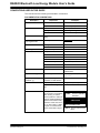
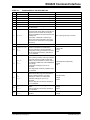
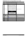
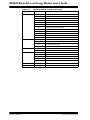
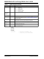
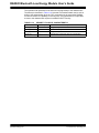
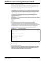
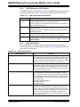
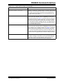
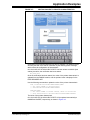
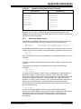
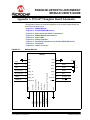
RN4020 Command Interface TABLE 2-1: Pin Symbol 1 2 3 4 5 6 GND AIO2 AIO1 AIO0 UART TX UART RX 7 WAKE_SW 8 CMD/MLDP 9 GND 10 11 12 RN4020 MODULE PIN DESCRIPTION CONNECTION LED SCK PIO[1] MLDP_EV CS PIO[2] WS MOSI PIO[3] 13 MISO PIO[4] 14 CTS PIO[5] Description Ground. Bidirectional with programmable analog I/O. Bidirectional with programmable analog I/O. Bidirectional with programmable analog I/O. UART Transmit (TX). UART Receive (RX). Deep Sleep Wake; active-high to wake module from Deep Sleep. CMD – Command Mode – Module enters Command mode where UART commands and responses sent over UART are exchanged between the RN4020 command interpreter and the MCU host. MLDP Mode – Data Mode – Data through UART is sent over the Bluetooth Low Energy connection to the remote device using MLDP data service. Ground. Default state is output: Active-high indicates the module is connected to a remote device. Active-low indicates a disconnected state. Configurable as PIO[1] via software command. SCK for diagnostics and factory calibration if pin 17 is asserted. Default function is output used for MLDP data event indicator (red LED). Active-high indicates MLDP data received or UART console data pending. Low level indicates no events. Event only triggered in CMD mode, when CMD/MLDP (pin 8) is high. Configurable as PIO[2] via “|O” and “|I” commands. CS for diagnostics and factory calibration if pin 17 is asserted. Default function is an output used for an Activity indicator (blue LED). High level indicates the module is awake and active. Low level indicates the module is in a Sleep state. Accessible as PIO[3] via “|O” and “|I” commands. MOSI for diagnostics and factory calibration if pin 17 is asserted. Trigger pin to generate event @PIOH and @PIOL. MISO for diagnostics and factory calibration if pin 17 asserted. Function Ground 1.65V input, 1.35V out, and 30 mA max out 1.65V input, 1.35V out, and 30 mA max out 1.65V input, 1.35V out, and 30 mA max out Output from RN4020. The line is 3.3V TTL Input to RN4020. The line is 3.3V TTL Input; weak pull-down Input; active-high to enter Command Ground • Green LED • PIO[1] • SCK • MLDP Data Event (Red LED) • PIO[2] • CS • WS (Blue LED) • PIO[3] • MOSI • PIO[4] • MISO Reserved for CTS if hardware flow control is on • CTS (input) the UART. • PIO[5] 2014 Microchip Technology Inc. DS70005191B-page 17